Transfer Assembly14-273
|
A/T
Transfer Assembly14-273 |
Transfer Assembly14-273
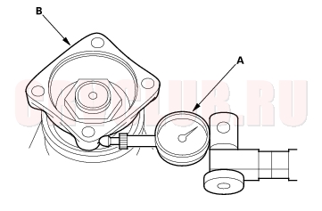
Inspection
STANDARD: 0.06 - 0.16 mm (0.02 - 0.06 in.)
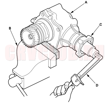
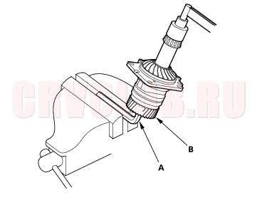
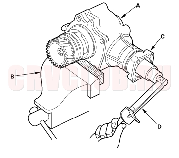
- Secure the transfer housing (A) in a bench vise (B) with soft jaws. To prevent damage to the transfer housing, always use soft jaws or equivalent materials between the transfer and the vise.
- Rotate the companion flange several times to seat the tapered roller bearings.
- Measure the staring torque at the companion flange (C) using a torque wrench (D).
STANDARD: 2.16 - 3.57 N·m (22.0 - 36.4 kgf·cm,
19.1 - 31.6 lbf·in)
- Remove the transfer from the vise.
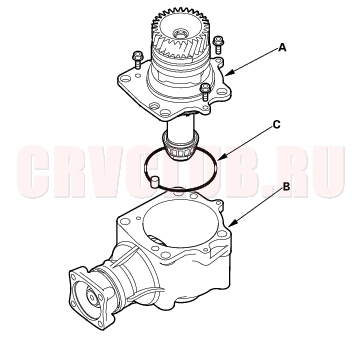
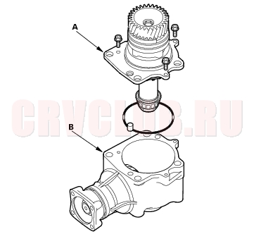
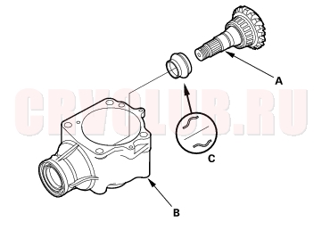
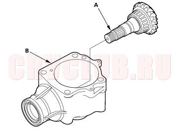
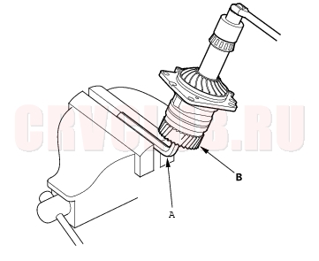
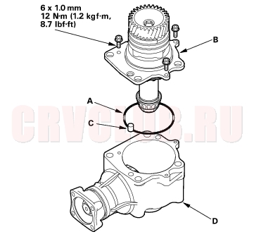
- Remove the transfer holder (A) from the transfer housing (B), then remove the O-ring (C) from the transfer holder.
- Apply Prussian Blue to both sides of the transfer drive gear teeth lightly and evenly.
- Install the transfer holder, and tighten the bolts. Do not install the O-ring on the transfer holder.
- Rotate the companion flange in both directions until the transfer gear rotate one full turn in both directions.
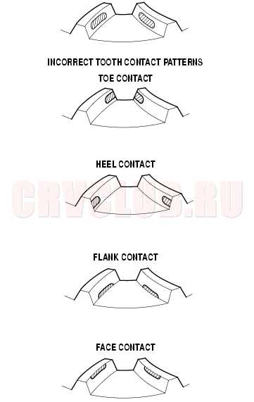
- Remove the transfer holder, and check the transfer drive gear tooth contact pattern. The pattern should be centered on the gear teeth as shown.
- If the measurements are out of standard or the tooth contact pattern are incorrect, disassemble the transfer assembly and repair it.
Disassembly14-274
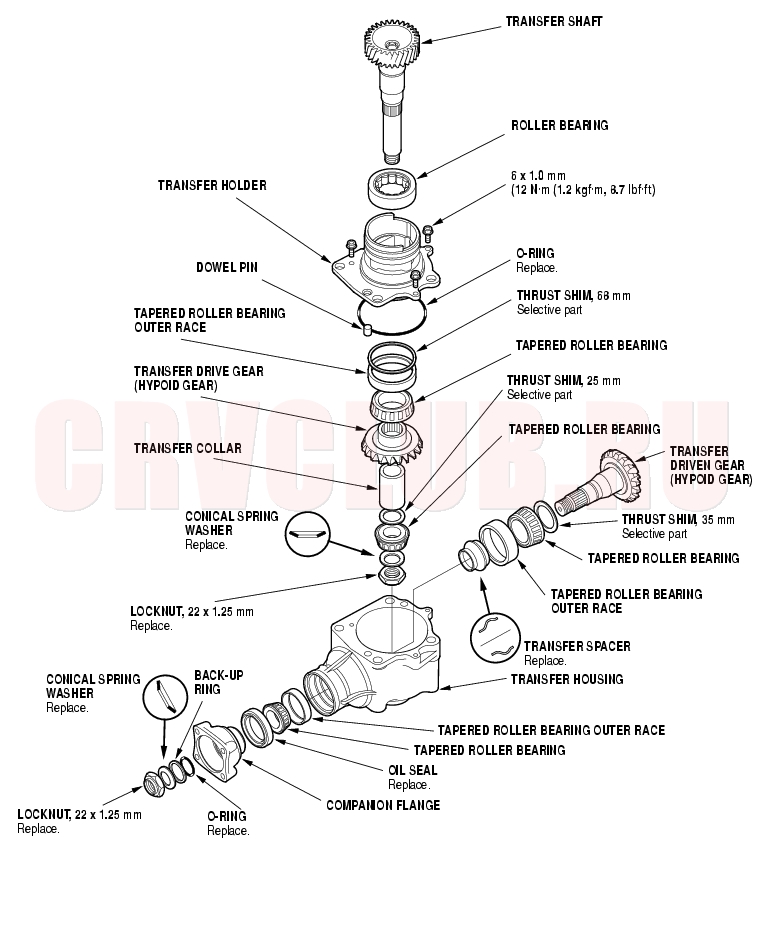
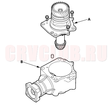
Exploded View
14-275
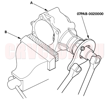
Special Tools Required
Companion flange holder 07PAB-0020000
NOTE: Refer to the Exploded View as needed during the following procedure.
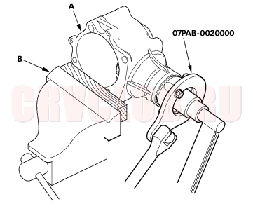
- Remove the transfer holder (A) from the transfer housing (B).
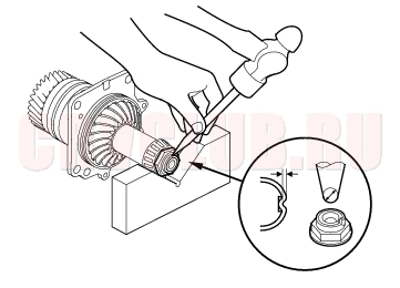
- Cut the lock tab on the locknut using a chisel.
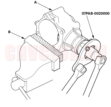
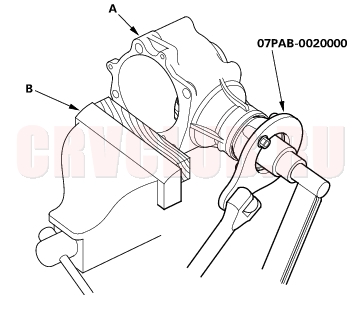
- Secure the transfer housing (A) in a bench vise (B) with soft jaws. To prevent damage to the transfer housing, always use soft jaws or equivalent materials between the transfer housing and the vise.
- Install the special tool on the companion flange, then loosen the locknut.
- Remove the special tool.
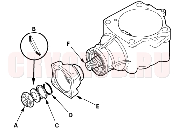
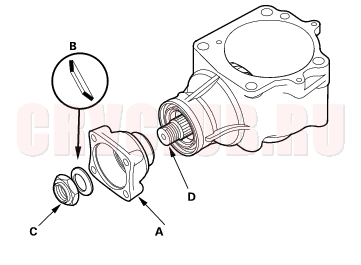
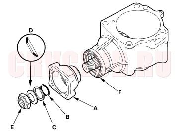
- Remove the locknut (A), conical spring washer (B), back-up ring (C), O-ring (D), and companion flange (E) from the transfer driven gear (F).
Disassembly (cont'd)14-276
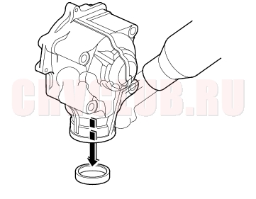
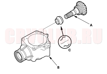
- Remove the transfer driven gear (A) from the transfer housing (B), then remove the transfer spacer (C) from the transfer driven gear.
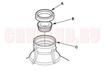
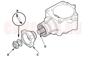
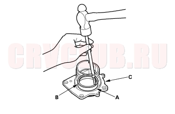
- Remove the oil seal (A) and tapered roller bearing (B) from the transfer housing (C).
Transfer Holder Disassembly14-277
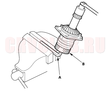
- Cut the lock tab on the locknut of the transfer shaft using a chisel.
- Put a 14 mm Allen wrench (A) in the transfer shaft (B), then secure the Allen wrench in a bench vise.
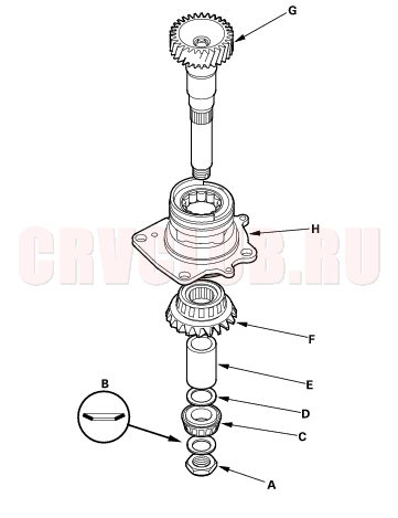
- Remove the locknut (A) and conical spring washer (B).
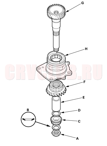
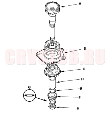
- Remove the tapered roller bearing (C), 25 mm thrust shim (D), transfer collar (E), transfer drive gear (F), and transfer shaft (G) from the transfer holder (H).
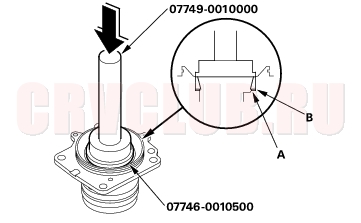
Transfer Holder Roller Bearing Replacement14-278
Special Tools Required
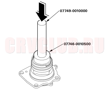
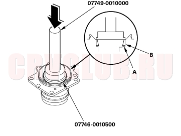
Handle driver 07749-0010000 Driver attachment, 62 x 68 mm 07746-0010500
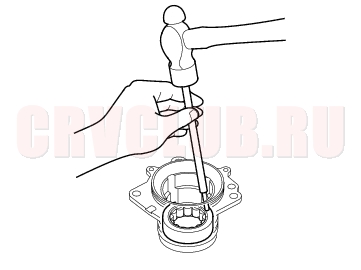
- Remove the roller bearing from the transfer holder.
- Install the new roller bearing in the transfer holder with the special tools.
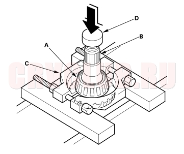
Transfer Holder Tapered Roller Bearing Outer Race Removal/Installation14-278
Special Tools Required
Handle driver 07749-0010000 Driver attachment, 62 x 68 mm 07746-0010500
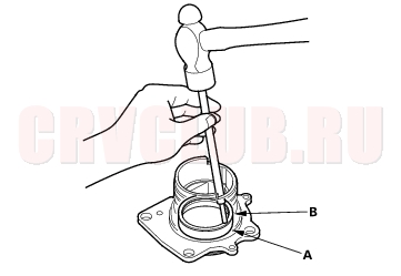
- Remove the tapered roller bearing outer race (A) and 68 mm thrust shim (B) form the transfer holder.
- Install the 68 mm thrust shim (A) in the transfer holder, then install the tapered roller bearing outer race (B) with the special tools.
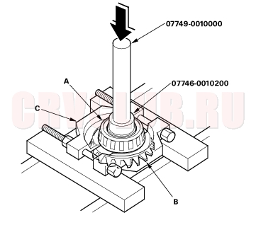
Transfer Drive Gear Bearing Replacement14-279
Special Tools Required
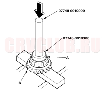
Handle driver 07749-0010000 Driver attachment, 37 x 40 mm 07746-0010200 Driver attachment, 42 x 47 mm 07746-0010300
- Remove the tapered roller bearing (A) from the transfer drive gear (B) with the special tools, bearing separator (C) and a press.
- Install the new tapered roller bearing (A) on the transfer drive gear (B) with the special tools and a press.
Transfer Driven Gear Bearing Removal/Installation14-279
Special Tools Required
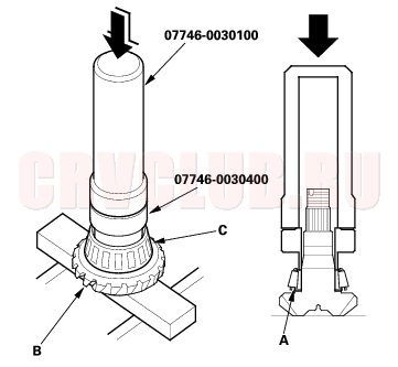
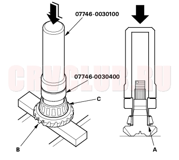
Driver 40 mm I.D. 07746-0030100 Driver attachment, 35 mm I.D. 07746-0030400
- Remove the tapered roller bearing (A) from the transfer driven gear (B) with a bearing separator (C) and a press. Place a shaft protector (D) between the transfer driven gear and a press to prevent damaging the transfer driven gear.
- Install the 35 mm thrust shim (A) on the transfer driven gear (B).
- Install the tapered roller bearing (C) on the transfer driven gear with the special tools and a press.
Transfer Housing Tapered Roller Bearing Outer Race Replacement14-280
Special Tools Required
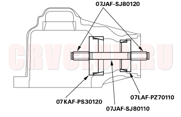
Handle driver 07749-0010000 Oil seal driver attachment 07947-SD90101 Bearing installer attachment 07KAF-PS30120 Bearing installer attachment 07LAF-PZ70110 Installer shaft 14 x 165 mm 07JAF-SJ80110 Installer nuts 14 mm 07JAF-SJ80120 NOTE: Replace the bearing with a new one whenever the outer race is replaced.
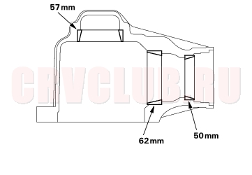
- Remove the bearing outer races from the transfer housing by heating the housing to about 212°F (100°C) with a heat gun. Do not heat the housing more than 212°F (100°C).
- NOTE: Some 57 mm bearing outer races are not press-fitted, and can be removed without heating the housing.
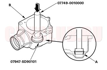
- Install the 57 mm bearing outer race (A) in the housing (B) with the special tools.
- Install the 62 mm bearing outer race and 50 mm bearing outer race in the housing with the special tools.
Reassembly14-281
Special Tools Required
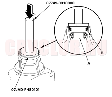
Driver 40 mm I.D. 07746-0030100 Driver attachment, 35 mm I.D. 07746-0030400 Handle driver 07749-0010000 Oil seal driver attachment 07JAD-PH80101 Companion flange holder 07PAB-002000 Driver attachment, 62 x 68 mm 07746-0010500
While reassembling the transfer assembly:
Check and adjust the transfer gear tooth contact. Measure and adjust the transfer gear backlash. Check and adjust the tapered roller bearing starting torque. Coat all parts with ATF during reassembly. Replace the tapered roller bearing and the bearing outer race as a set if either part is replaced. Replace the transfer drive gear and the transfer driven gear as a set if either part is replaced.
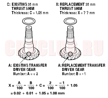
- Select the 35 mm thrust shim if the transfer driven gear is replaced. Calculate the thickness of the 35 mm thrust shim using the formula below, and select the shim from the table below.
- NOTE: The number on the transfer driven gear is shown in 1/100 mm.
A: Number on the existing transfer driven gear
B: Number on the replacement transfer driven gear
C: Thickness of the existing 35 mm thrust shim
X: Thickness needed for the replacement 35 mm thrust shim
Select No. M 35 mm thrust shim of 1.08 mm in this case.
- Select the 35 mm thrust shim if the tapered roller bearing on the transfer driven gear is replaced. Measure the thickness of the replacement bearing and the existing bearing, and calculate the difference of the bearing thickness. Adjust the thickness of the existing 35 mm thrust shim by the amount of the difference in bearing thickness, and select the replacement 35 mm thrust shim from the above table.
Reassembly (cont'd)14-282
- Install the 35 mm thrust shim (A) on the transfer driven gear (B), then install the tapered roller bearing (C) with the special tools and a press.
- Place the tapered roller bearing (A) on the bearing outer race of the companion flange side of the transfer housing.
- Install the new oil seal (B) on the transfer housing with the special tools and a press.
- Install the transfer driven gear (A) in the transfer housing (B). Do not install the transfer spacer on the transfer driven gear.
- Install the companion flange (A), conical spring washer (B), and locknut (C) on the transfer driven gear (D). Do not install the O-ring and back-up ring.
14-283
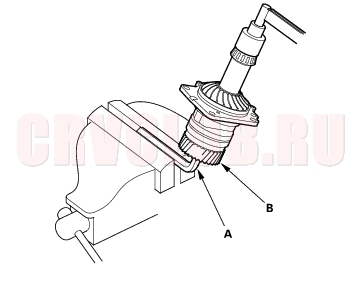
- Secure the transfer housing (A) in a bench vise (B) with soft jaws. To prevent damage to the transfer housing, always use soft jaws or equivalent materials between the transfer housing and the vise.
- Install the special tool on the companion flange.
- Tighten the locknut while measuring the starting torque so the starting torque is within 0.98 - 1.39 N·m (10.0 - 14.2 kgf·cm, 8.7 - 12.3 lbf·in). Do not stake the locknut in this step.
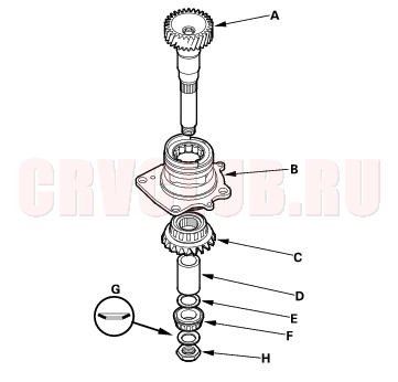
- Install the transfer shaft (A) in the transfer holder (B), and install the transfer drive gear (C), transfer collar (D), 25 mm thrust shim (E), tapered roller bearing (F), conical spring washer (G), and locknut (H).
- Put a 14 mm Allen wrench (A) in the transfer shaft (B), then secure the Allen wrench in a bench vise.
- Tighten the locknut 118 N·m (12.0 kgf·m, 86.8 lbf·ft). Do not stake the locknut in this step.
Reassembly (cont'd)14-284
- Apply Prussian Blue to both sides of the transfer drive gear teeth lightly and evenly.
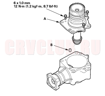
- Temporarily install the transfer holder (A) and dowel pin (B) without O-ring, and tighten the bolts.
- Rotate the companion flange in both directions until the transfer gear rotate one full turn in both directions.
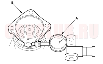
- Set a dial indicator (A) on the companion flange (B).
- Measure the transfer gear backlash.
STANDARD: 0.06 - 0.16 mm (0.02 - 0.06 in.)
14-285
- If the measurement of the backlash is out of standard, adjust the transfer gear backlash with the 35 mm thrust shim and recheck. Do not use more than two 35 mm thrust shims to adjust the transfer gear backlash.
- If the transfer gear tooth contact is incorrect, adjust the transfer gear tooth contact with the 25 mm or 35 mm thrust shim. Do not use more than two shims of each thrust shim to adjust the tooth contact.
- Toe Contact
- Use a thicker 35 mm thrust shim to move the transfer driven gear toward the transfer drive gear. Because this movement causes the transfer gear backlash to change, move the transfer drive gear away from the transfer driven gear to adjust the transfer gear backlash as follows:
- Increase the thickness of the 25 mm thrust shim.
- Reduce the thickness of the 68 mm thrust shim by the amount of increase of the 25 mm thrust shim.
- Heel Contact
- Use a thinner 35 mm thrust shim to move the transfer driven gear away from the transfer drive gear. Because this movement causes the transfer gear backlash to change, move the transfer drive gear toward the transfer driven gear to adjust the transfer gear backlash as follows:
- Reduce the thickness of the 25 mm thrust shim.
- Increase the thickness of the 68 mm thrust shim by amount of reduce thickness of the 25 mm thrust shim.
- Flank Contact
- Use a thinner thrust shim to move the transfer drive gear toward the transfer driven gear. Flank contact must be adjusted within the limits of the transfer gear backlash. If the backlash exceeds the limits, adjust as described under Heel Contact.
- Face Contact
- Use a thicker thrust shim to move the transfer drive gear away from the transfer driven gear. Face contact must be adjusted within the limits of the transfer gear backlash. If the backlash exceeds the limits, adjust as described under Toe Contact.
- Remove the transfer holder (A) from the transfer housing (B) after adjusting the transfer gear backlash or transfer gear tooth contact.
Reassembly (cont'd)14-286
- Secure the transfer housing (A) in a bench vise (B) with soft jaws. To prevent damage to the transfer housing, always use soft jaws or equivalent materials between the transfer housing and the vise.
- Install the special tool on the companion flange, then loosen the locknut.
- Remove the locknut (A), conical spring washer (B), and companion flange (C) from the transfer driven gear (D).
- Remove the transfer driven gear (A) from the transfer housing (B).
- Install the new transfer spacer (C) on the transfer driven gear in the direction shown, and install them in the transfer housing.
- Coat the threads of the locknut and transfer driven gear with ATF.
- Install the companion flange (A), new O-ring (B), back-up ring (C), new conical spring washer (D), and new locknut (E) on the transfer driven gear (F). Install the conical spring washer in the direction shown.
14-287
- Secure the transfer housing (A) in a bench vise (B) with soft jaws. To prevent damage to the transfer housing, always use soft jaws or equivalent materials between the transfer housing and the vise.
- Install the special tool on the companion flange.
- Tighten the locknut while measuring the starting torque of the transfer driven gear.
STARTING TORQUE:
0.98 - 1.39 N·m (10.0 - 14.2 kgf·cm, 8.7 - 12.3 lbf·in)
TIGHTENING TORQUE:
132 - 260 N·m (13.5 - 26.5 kgf·m, 97.6 - 192 lbf·ft)
NOTE: Rotate the companion flange several turns to seat the tapered roller bearings, then measure the starting torque. If the starting torque exceeds 1.39 N·m (14.2 kgf·cm, 12.3 lbf·in), replace the transfer spacer and reassemble the parts. Do not adjust the starting torque with the locknut loose. If the tightening torque exceeds 260 N·m (26.5 kgf·m, 192 lbf·ft), replace the transfer spacer and reassemble the parts.
- Remove the special tool.
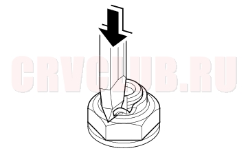
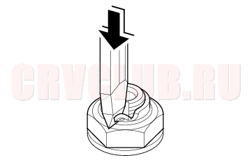
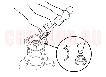
- Stake the locknut using a 3.5 mm punch.
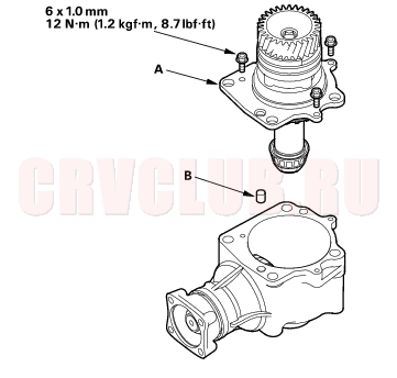
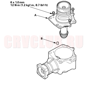
- Temporarily install the transfer holder (A) and dowel pin (B) without the O-ring, and tighten the bolts.
Reassembly (cont'd)14-288
- Secure the transfer housing (A) in a bench vise (B) with soft jaws. To prevent damage to the transfer housing, always use soft jaws or equivalent materials between the transfer and the vise.
- Rotate the companion flange several times to seat the tapered roller bearings.
- Measure the staring torque at the companion flange (C) using a torque wrench (D).
STANDARD: 2.16 - 3.57 N·m
(22.0 - 36.4 kgf·cm, 19.1 - 31.6 lbf·in)
- Remove the transfer holder from the transfer housing.
- If the measurement is within the standard, go to step 53.
- If the measurement is out of standard, put a 14 mm Allen wrench (A) in the transfer shaft (B), then secure the Allen wrench in a bench vise.
- Loosen the locknut.
14-289
- Remove the locknut (A) and conical spring washer (B).
- Remove the tapered roller bearing (C), 25 mm thrust shim (D), transfer collar (E), transfer drive gear (F), and transfer shaft (G) from the transfer holder (H).
- Remove the tapered roller bearing outer race (A) and the 68 mm thrust shim (B) from the transfer holder (C).
- Measure the thickness of the 68 mm thrust shim, and select the new 68 mm thrust shim.
Reassembly (cont'd)14-290
- Install the new 68 mm thrust shim (A) in the transfer holder, then install the tapered roller bearing outer race (B) with the special tools.
- Install the transfer shaft (A) in the transfer holder (B), and install the transfer drive gear (C), transfer collar (D), 25 mm thrust shim (E), tapered roller bearing (F), conical spring washer (G), and locknut (H). Install the conical spring washer in the direction shown.
- Put a 14 mm Allen wrench (A) in the transfer shaft (B), then secure the Allen wrench in a bench vise.
- Tighten the locknut 118 N·m (12.0 kgf·m, 86.8 lbf·ft). Do not stake the locknut in this step.
- Temporarily install the transfer holder (A) and dowel pin (B) without the O-ring, and tighten the bolts.
- Rotate the companion flange several turns to seat the tapered roller bearings, and recheck the starting torque. Remove the transfer holder after adjusting the starting torque.
14-291
|
A/T
Transfer Assembly14-273 |