System Description22B-7
|
Navigation System22B-1
System Description22B-7 |
System Description22B-7
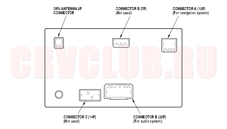
Connector Locations
AVN unit
System Description (cont'd)22B-8
AVN Unit Inputs and Outputs for Connector A (12P)
22B-9
AVN Inputs and Outputs for GPS antenna 2P Connector
1 ---- GPS GPS GPS signal 2 ---- GPS GND GPS ground Ground for GPS antenna
System Description (cont'd)22B-10
Overview
The Honda Navigation System is a highly-sophisticated, hybrid locating system that uses satellites and a map database to show you where you are and to help guide you to a desired destination.
The Navigation System receives signals from the Global Positioning System (GPS), a network of 24 satellites in orbit around the earth. By receiving signals from serveral of these satellites, the Navigation System can determine the latitude and longitude of the vehicle. In addition, signals from the system's yaw rate sensor and the vehicle speed pulse (VSP) sensor enable the system to keep track of the vehicle's direction and speed of travel.
This hybrid system has advantages over a system that is either entirely self-contained or one that relies totally on the GPS. For example, the self-contained portion of the system can keep track of vehicle position even when satellite signals cannot be received, and the GPS can keep track of the vehicle position even when the vehicle is transported by ferry.
The Navigation System applies all this location, direction, and speed information to the maps and calculates a route to the destination entered. As you drive to that destination, the system provides both visual and audio guidance.
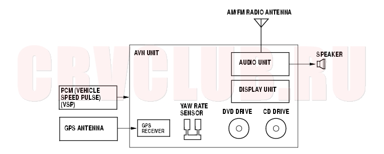
System Diagram
22B-11
Navigation Function
The navigation system is composed of the AVN unit, the PCM vehicle speed pulse (VSP) signal, the GPS antenna.
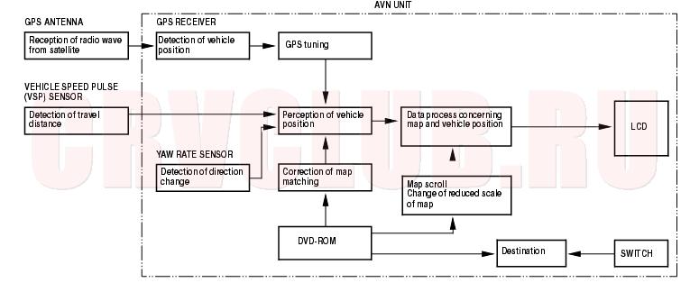
Function Diagram
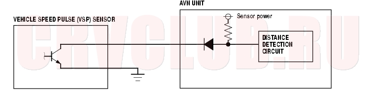
Vehicle Speed Pulse (VSP)
The vehicle speed pulse (VSP) is outputted by the PCM. The PCM recieves the signal from the countershaft speed sensor, then the PCM prosesses the signal and transmits it to the speedometer and other systems.
Yaw Rate Sensor
The yaw rate sensor detects the direction change (angular speed) of the vehicle. The sensor is oscillation gyro built into the AVN unit.
System Description (cont'd)22B-12
Global Positioning System (GPS)
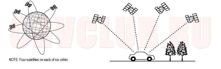
The Global Positioning System (GPS) enables the navigation system to determine the current position of the vehicle by using the electronic waves transmitted from the satellites in orbit around the earth. The satellites transmit the satellite identification signal, orbit information, transmission time signal, and other information. When the GPS receiver receives the electronic waves from three or more satellites simultaneously, it calculates the current position of the vehicle based on the distance to each satellite and the satellite positions on their respective orbits.
Position detection Image with GPS satellite
Precision of GPS
The precision of the GPS varies according to the number of satellites from which electronic waves are received and the control condition. The precision is indicated by the GPS mark shown on the upper left of the display.
GPS Antenna
Receiving the electronic waves from the satellites, the GPS antenna amplifies and transmits them to the GPS receiver.
GPS Receiver
The GPS receiver is built in to AVN unit. It calculates the vehicle position by receiving the signal from the GPS antenna. The vehicle position and signal reception condition is transmitted from the GPS receiver to the AVN unit to adjust the vehicle position.
22B-13
AVN Unit
The AVN unit calculates the vehicle position and guides you to the destination. The unit performs map matching correction, GPS correction, and distance tuning. It also controls the menu functions and the DVD-ROM drive. With control of all these items, the AVN unit makes the navigation picture signal, then it transmits the signal to the display unit and audio driving instructions to the audio unit.
Calculation of Vehicle Position
The AVN unit calculates the vehicle position (the driving direction and the current position) by receiving the directional change signals from the yaw rate sensor and the travel distance signals from the vehicle speed pulse (VSP) sensor.
Map Matching Tuning
The map matching tuning is accomplished by indicating the vehicle position on the roads on the map. The map data transmitted from the DVD-ROM is checked against the vehicle position data, and the vehicle position is indicated on the nearest road. Map matching tuning does not occur when the vehicle travels on a road not shown on the map, or when the vehicle position is far away from a road on the map.
GPS Tuning
The GPS tuning is accomplished by indicating the vehicle position as the GPS's vehicle position. The AVN unit compares its calculated vehicle position data with the GPS vehicle position data. If there is large difference between the two, the indicated vehicle position is adjusted to the GPS vehicle position.
Distance Tuning
The distance tuning reduces the difference between the travel distance signal from the VSP and the distance data on the map. The AVN unit compares its calculated vehicle position data with the GPS vehicle position data. The AVN unit then decreases the tuning value when the vehicle position is always ahead of the GPS vehicle position, and it increases the tuning value when the vehicle position is always behind the GPS vehicle position.
Route Guidance
The AVN unit can calculate different routes to a selected destination. You have four options:
Direct Route - Calculate a route that is the most direct and will take the least time. Easy Route - Calcute a route that minimizes the number of turns needed. Minimize Motorways - Calculate a route that avoids motorway travel. If that is not possible, keep the amount of motorway travel to a minimum. Minimize Toll Roads - Calculate a route that avoids, or minimizes travel on toll roads. Audio Guidance
The AVN unit transmits audio driving instructions before entering an intersection or passing a junction.
The audio instructions come through audio unit and the front speakers.
DVD-ROM
The map data (including all scale rates) is stored in the DVD-ROM. The map data includes:
Road distances, road widths, speed limits, traffic regulations, passing time at junction, distances to junctions, and the driving instructions for audio guidance. Latitude and longitude GPS. System Description (cont'd)22B-14
Audio Unit
The audio unit built in the AVN unit. It receives the audio driving instructions from the navigation unit and transmits the instructions through the front speakers even when the audio system is in use.
Display Unit
The display unit built in the AVN unit. It uses Liquid Crystal Display (LCD). The LCD is a 6-inch-wide, Thin Film Transistor (TFT), stripe type with about 280,000 picture elements. The color film and fluorecent light are laid out on the back of the liquid crystal film.
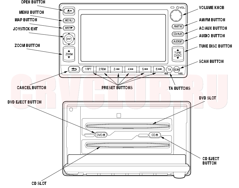
Operation keys
|
Navigation System22B-1
System Description22B-7 |