Power Mirrors 22A-130
|
Body Electrical22A-1
Power Mirrors 22A-130 |
Power Mirrors 22A-130
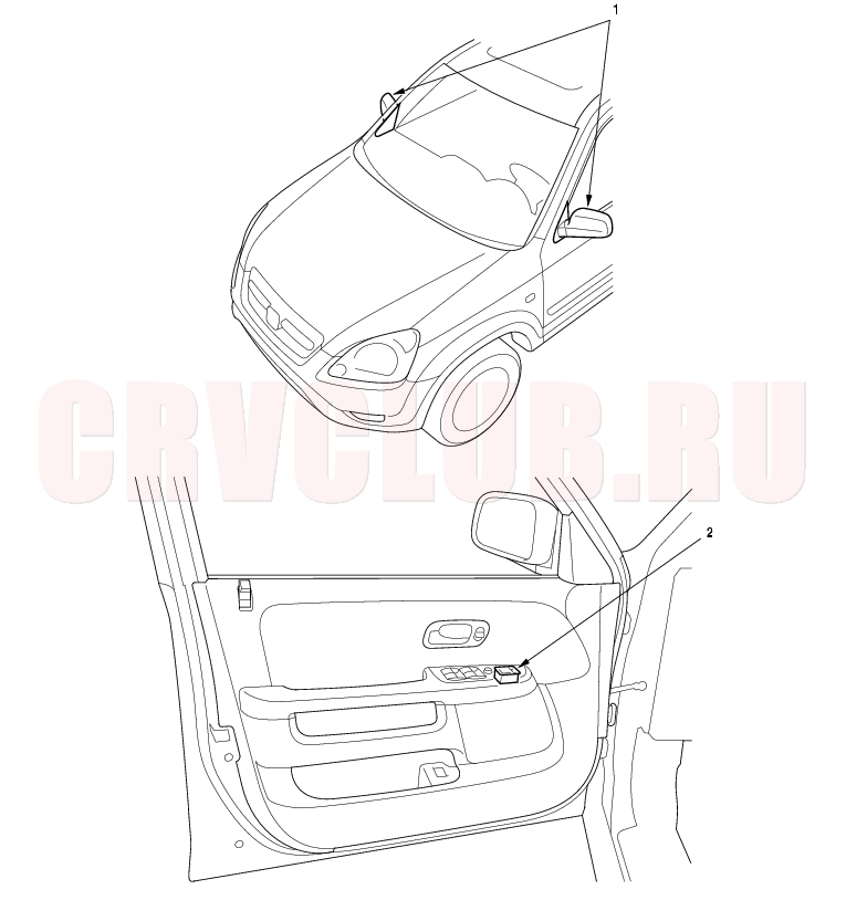
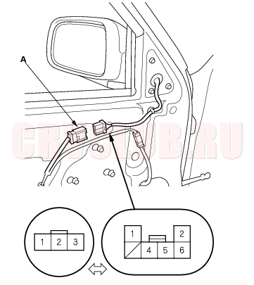
Component Location Index
NOTE: LHD type is shown, RHD type is symmetrical.
Function Test, page 22A-144 ; Replacement, page 22A-154 ; Mirror Actuator Test, page 22A-149 ; Mirror Actuator Replacement, page 22A-151 Test, page 22A-147 ; Replacement, page 22A-147
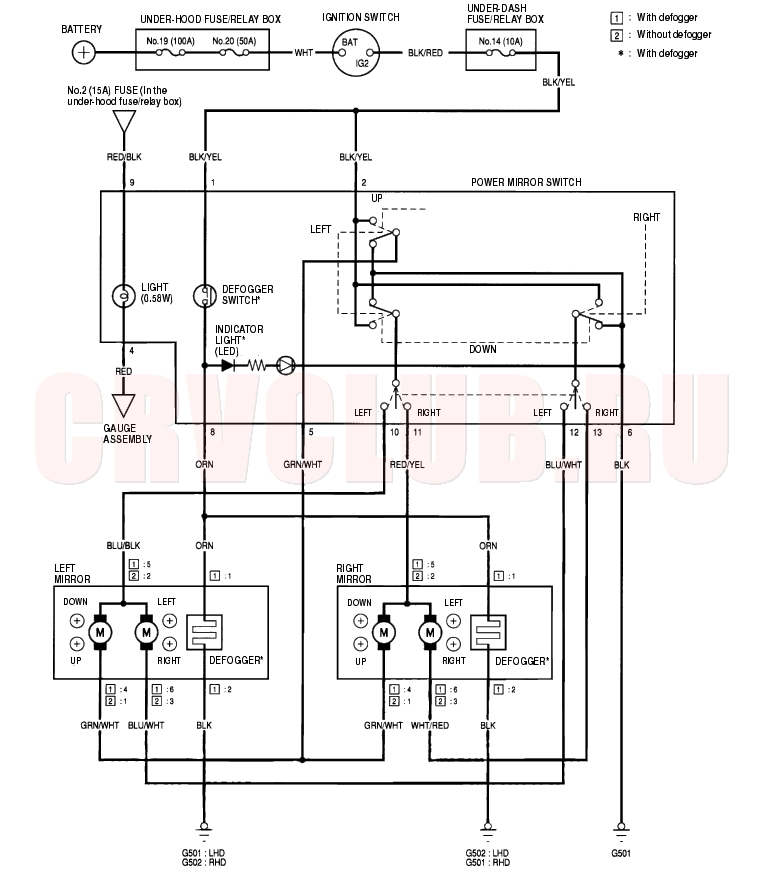
Circuit Diagram 22A-131
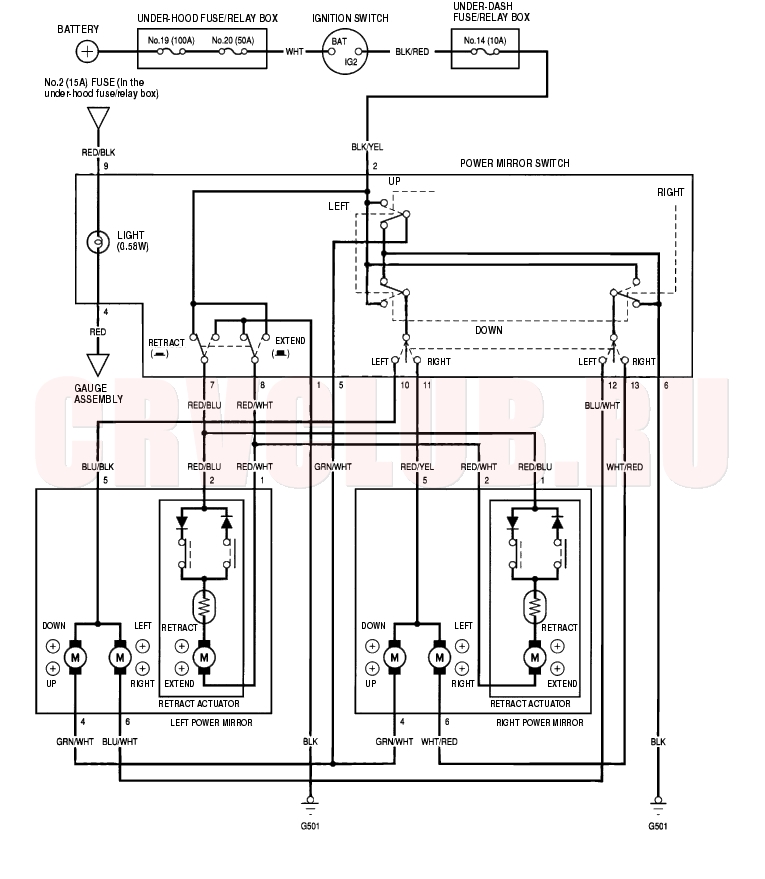
Circuit Diagram - With Retract Power Mirror 22A-132
Function Test 22A-133
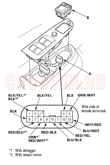
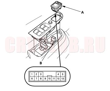
- Remove the driver's switch panel (A) (see page 20-9) .
- Disconnect the 13P connector (A) from the switch (B).
- Choose the appropriate test based on the symptom:
- Both mirrors don't work, go to step 4.
- Left mirror doesn't work, go to step 6.
- Right mirror doesn't work, go to step 7.
- Defoggers don't work, go to step 8.
- Retract actuators don't work, go to step 9.
Both mirrors
- Check for voltage between the No. 2 terminal and body ground with the ignition switch ON (II).
There should be battery voltage.
- If there is no battery voltage, check for:
- blown No. 14 (10A) fuse in the under-dash fuse/relay box.
- an open in the BLK/YEL wire.
- If there is battery voltage, go to step 5.
- Check for continuity between the No. 6 terminal and body ground.
There should be continuity.
- If there is no continuity, check for:
- an open in the BLK wire.
- poor ground (G501).
- If there is continuity, check both mirrors individually as described in the next column.
Left mirror
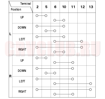
- Connect the No. 2 terminal to the No. 10 terminal, and the No. 5 (or No. 12) terminal to No. 6 terminal with jumper wires. The left mirror should tilt down (or swing left) with the ignition switch ON (II).
- If the mirror does not tilt down (or does not swing left), check for an open in the GRN/WHT (or BLU/WHT) wire between the left mirror and the 13P connector. If the wire is OK, check the left mirror actuator.
- If the mirror neither tilts down nor swings left, repair the BLU/BLK wire.
- If the mirror works properly, check the mirror switch.
Right mirror
- Connect the No. 2 terminal to the No. 11 terminal, and the No. 5 (or No. 13) terminal to No. 6 terminal with jumper wires. The right mirror should tilt down (or swing left) with the ignition switch ON (II).
- If the mirror does not tilt down (or does not swing left), check for an open in the GRN/WHT (or WHT/RED) wire between the right mirror and the 13P connector. If the wire is OK, check the right mirror actuator.
- If the mirror neither tilts down nor swings left, repair the RED/YEL wire.
- If the mirror works properly, check the mirror switch.
Function Test (cont'd) 22A-134
Defogger
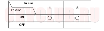
- Connect the No. 1 and No. 8 terminals with a jumper wire, and check for voltage between the BLK wire terminal of the mirror connector and body ground. There should be battery voltage and both mirrors should warm up with the ignition switch ON (II).
- If there is no voltage or neither warms up, check for:
- an open in the BLK/YEL or ORN wire.
- blown No. 14 (10A) fuse in the under-dash fuse/relay box.
- If only one fails to warm up, check its defogger.
- poor ground (G501, G502).
- If both warm up, check the defogger switch.
Retractable mirror
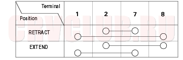
- Connect the No. 2 terminal to the No. 7 (or No. 8) terminal with a jumper wire. The mirrors should retract (or extend) when the ignition switch is turned back and forth between ON (II) and OFF.
- If the mirrors neither retract nor extend, check for an open in the RED/BLU or RED/WHT wire between the switch and the mirrors.
- If one of the mirrors does not retract or extend, check the retractable mirror actuator.
Power Mirror Switch Test/Replacement 22A-135
- Remove the driver's switch panel (see page 20-9) .
- Remove the power mirror switch (A).
- Disconnect the 13P connector (B) from the switch.
- Check for continuity between the terminals in each switch position according to the table.
Mirror Switch:
Defogger Switch:
Retract Switch:
Power Mirror Actuator Test 22A-136
- Remove the door panel (see page 20-9) .
- Disconnect the 6P or 3P connector (A) from the power mirror actuator.
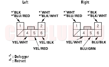
- 3P connector: without defogger or retract
- 6P connector: with defogger or retract
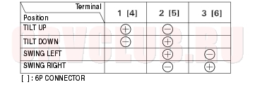
- Check actuator operation by connecting battery power and ground according to the table.
- If the mirror fails to work properly, replace the mirror actuator (see page 22A-151) .
Defogger Test:
- Check for continuity between the No. 1 and No. 2 terminals of the 6P connector. There should be continuity.
- If the continuity is not as specified, replace the mirror actuator.
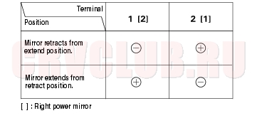
Retract Switch:
- Check actuator operation by connecting battery power and ground according to the table.
- If the retract actuator fails to work properly, replace the mirror.
Power Mirror Actuator Replacement 22A-137
- Remove the mirror holder, and disconnect the mirror defogger connectors* (see page 20-40) .
- *: With defogger
- Remove the power mirror (see page 20-39) .
- Disconnect the 3P or 6P connector from the mirror.
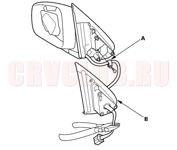
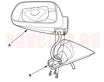
- Remove the screw from the harness clip (A).
- Cut the wire harness with cutter, and remove the gasket (B).
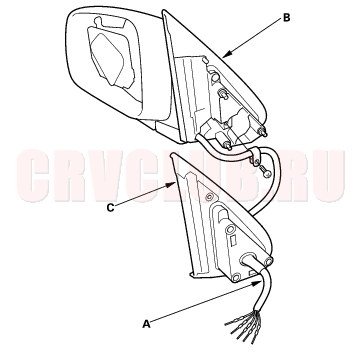
- Remove the three screws, and separate the mirror housing (A) from the bracket (B).
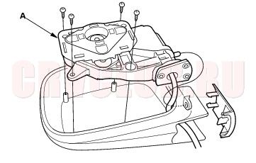
- Remove the four screws and the actuator (A).
Power Mirror Actuator Replacement (cont'd) 22A-138
- Route the wire harness (A) of the new actuator through the hole in the bracket (B) and gasket (C).
- Install the actuator, bracket, harness clip, and gasket in the reverse order of removal.
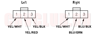
- Insert the new actuator terminals into the connector in the original arrangement as shown below.
3P CONNECTOR:
6P CONNECTOR:
- Apply tape to seal the intersection of the wire harness and the gasket.
- Reassemble in the reverse order of disassembly. Be careful not to break the mirror when reinstalling it to the actuator (see page 20-40) .
- Reinstall the mirror assembly to the door.
- Operate the power mirror to ensure smooth operation.
|
Body Electrical22A-1
Power Mirrors 22A-130 |