Doors20-2
|
Body20-1
Doors20-2 |
Doors20-2
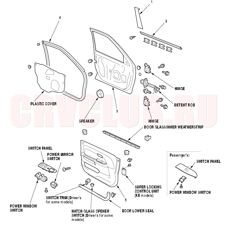
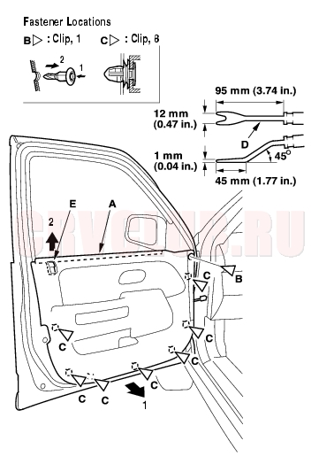
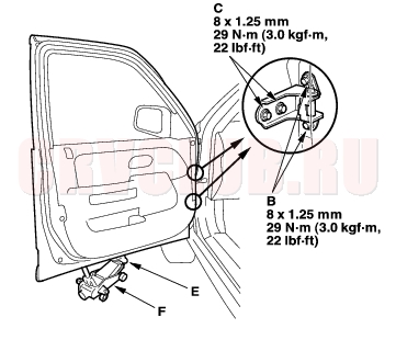
Component Location Index - Front Door
Replacement, page 20-19 Replacement, page 20-17 Position Adjustment, page 20-36 Replacement, page 20-18 Removal/Installation, page 20-9
20-3
Replacement, page 20-16 ; Adjustment, page 20-34 Replacement, page 20-16
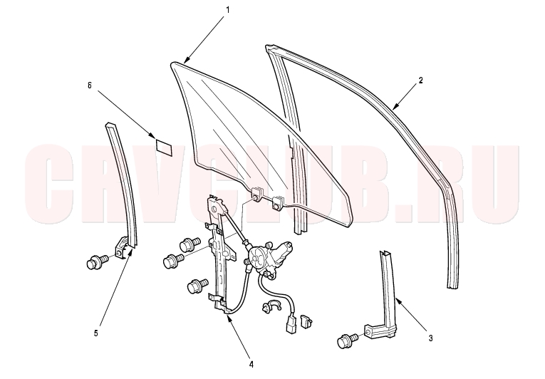
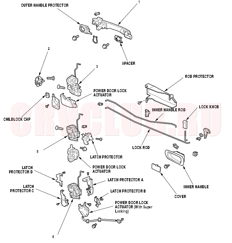
Component Location Index - Front Door (cont'd)20-4
Replacement, page 20-11 Replacement, page 20-14 Adjustment, page 20-37 Replacement, page 20-14
20-5
With Super Locking:
Replacement, page 20-11 Adjustment, page 20-37 Replacement, page 20-14
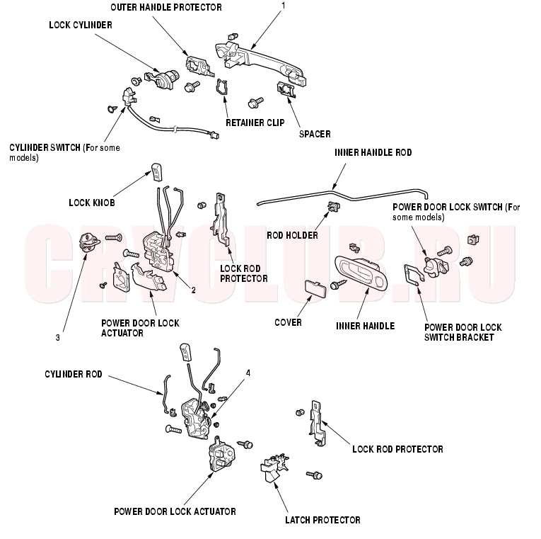
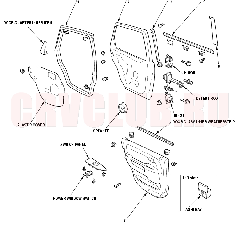
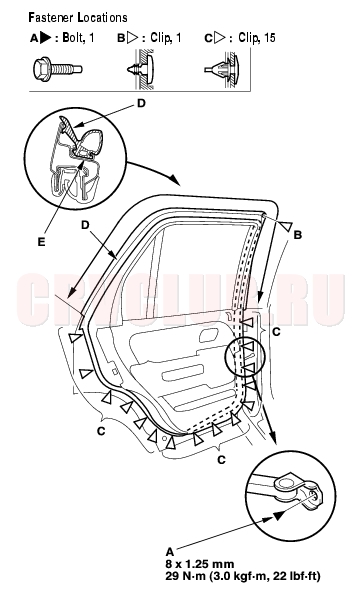
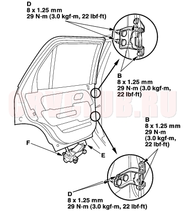
Component Location Index - Rear Door20-6
Replacement, page 20-30 Position Adjustment, page 20-36 Replacement, page 20-31 Replacement, page 20-30 Replacement, page 20-32 Removal/Installation, page 20-21
20-7
Replacement, page 20-50 Replacement, page 20-27 ; Adjustment, page 20-34 Replacement, page 20-27
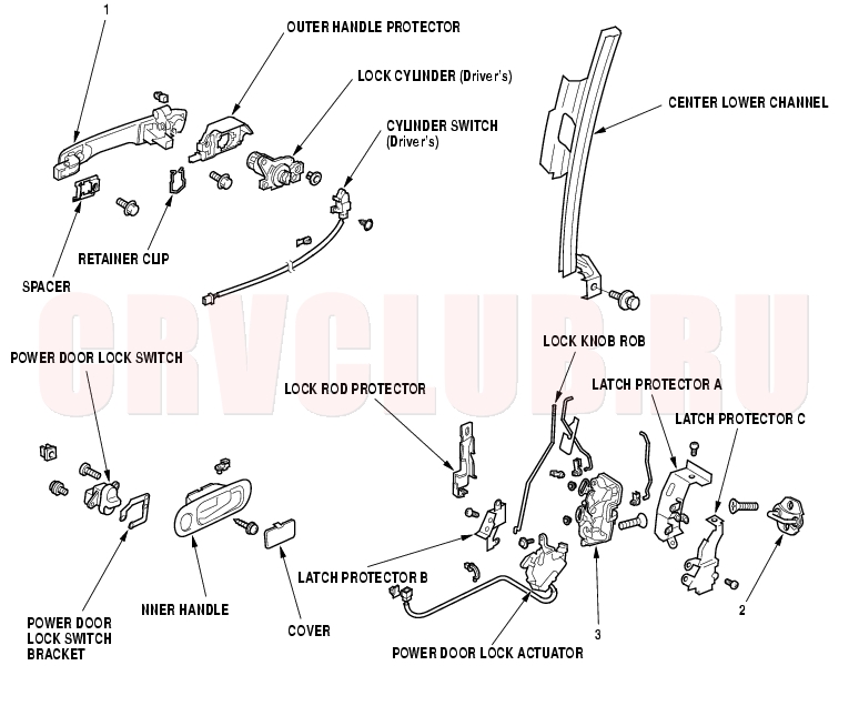
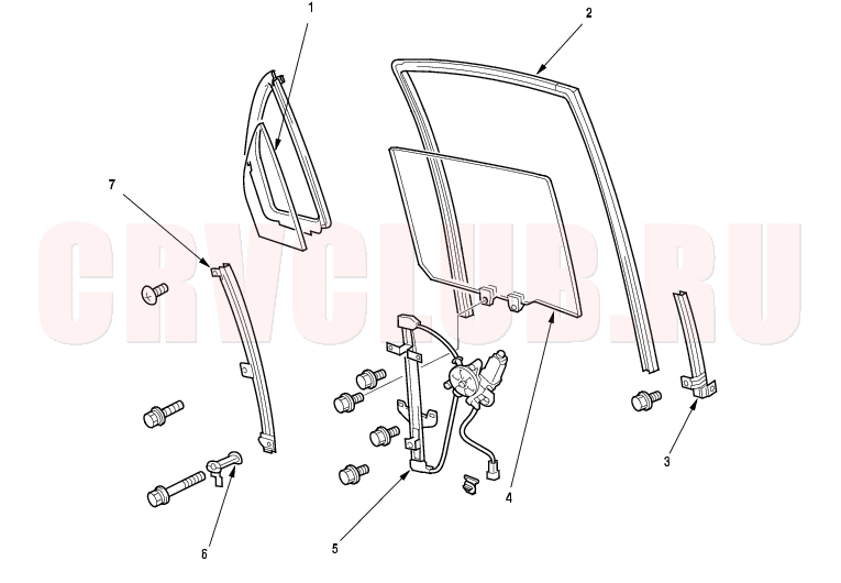
Component Location Index - Rear Door (cont'd)20-8
Replacement, page 20-23 Adjustment, page 20-37 Replacement, page 20-25 Replacement, page 20-25 Replacement, page 20-25
Front Door Panel Removal/Installation20-9
Special Tools Required
Trim pad remover, Snap-on A 177A or equivalent, commercially available.
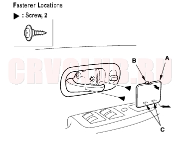
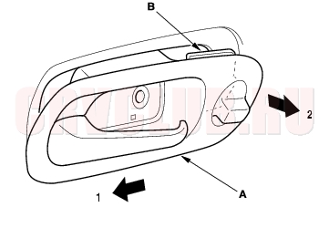
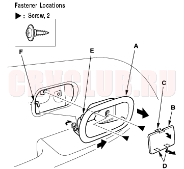
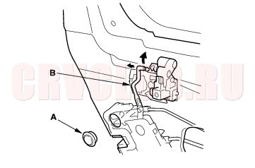
- Using a flat-tip screwdriver wrapped with protective tape, pry out on the upper portion of the cover (A) to release the hooks (B), then remove the cover.
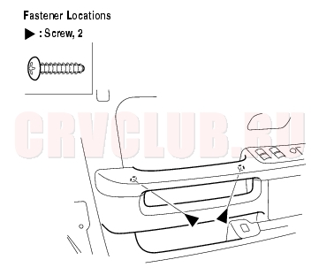
- Remove the screws.
- Driver's door with power door lock switch:
Pull out the inner handle (A) rearward and out half-way to release the power door lock switch bracket (B) from the door panel (C).
- Driver's door without power door lock switch, and passenger's door: Pull out the inner handle (A) half-way.
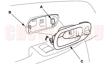
- If equipped, disconnect the power door lock switch connector (A) on driver's side.
- Disconnect the inner handle rod (B), then remove the inner handle (C).
Front Door Panel Removal/Installation (cont'd)20-10
- Lower the glass fully.
- Remove the screws from under the armrest.
- Passenger's door: Remove the switch panel (A).
- Insert a flat-tip screwdriver wrapped with protective tape through a hole under the armrest, and push up the back of the panel to release the rear hook (B).
- Pull out along the edge of the panel to release the hooks (C) and clip.
- Disconnect the power window switch connector (D).
- Remove the mirror mount cover (see step 2 on page 20-39 ).
- Remove the door panel (A) with as little bending as possible to avoid creasing or breaking it.
- Release the clip (B).
- Release the clips (C) that hold the door panel with a commercially available trim pad remover (D).
- Starting at the rear, pull the door panel upward, then release the lock knob (E).
20-11
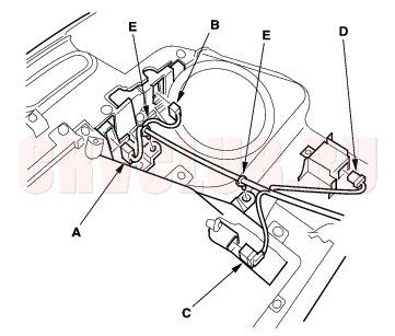
- Driver's door: Disconnect the power window switch connector (A), power mirror switch connector (B), and if equipped, disconnect the hatch glass opener switch connector (C) and super locking control unit connector (D), and detach the harness clips (E) from the back of the door panel. RHD is shown, LHD is symmetrical except it has no super locking control unit.
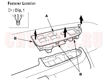
- Driver's door: Push up the back of the switch panel (A) to release the clip and hooks (B), then remove the panel.
- Install the panel in the reverse order of removal, and note these items:
- Replace any damaged clips.
- Make sure the connectors are plugged in properly, and the rod is connected properly.
Front Door Outer Handle Replacement20-11
NOTE: Put on gloves to protect your hands.
- Remove these items:
- Door panel (see page 20-9)
- Plastic cover, as necessary (see page 20-2)
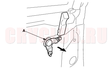
- Raise the glass fully.
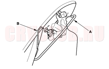
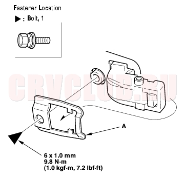
- Release the clip and detach the hook (A), then remove the lock rod protector (B).
Front Door Outer Handle Replacement (cont'd)20-12
- Disconnect the outer handle rod (A) and cylinder rod (B). Driver's with Super Locking : Disconnect the outer handle rod only. Without cylinder switch is shown (with cylinder switch is similar).
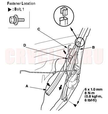
- Driver's with Super Locking : Pull the glass run channel (A) away as necessary. Remove the bolt, then remove the center lower channel (B) by pulling it downward, and pull the channel up to remove it from the outer handle rod (C) through the hole (D) in the channel.
- Driver's with Super Locking : Disconnect the cylinder rod (see step 4).
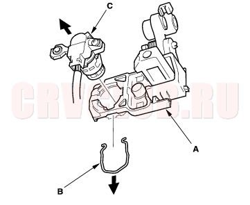
- Release the retainer clip (B) with a hocked shaped tool. On no Super Locking models, remove the lock cylinder (C).
Without Super Locking:
With Super Locking:
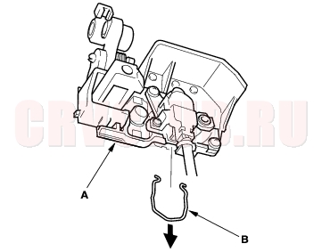
- On no Super Locking models with cylinder switch, remove the screw, then separate the lock cylinder (A) and cylinder switch (B).
20-13
- With cylinder switch: Disconnect the cylinder switch connector (A), and detach the harness clip (B), then remove the cylinder switch (C). With Super Locking is shown.
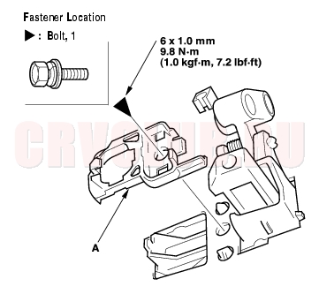
- Remove the bolt, then remove the cylinder protector (A). Without Super Locking and with Super Locking (passengers side) are shown, with Super Locking (driver's side) is that removing the lock cylinder and cylinder protector as an assembly.
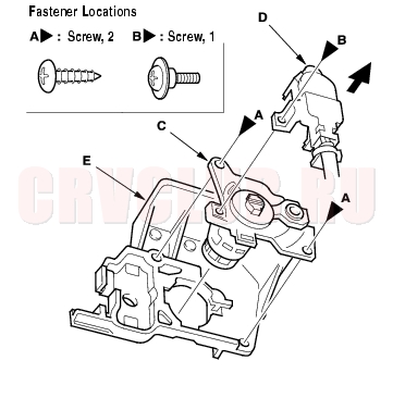
- With Super Locking: Remove the screws (A, B), then separate the lock cylinder (C), cylinder switch (D), and cylinder protector (E).
- Remove the bolt, then remove the spacer (A).
Front Door Outer Handle Replacement (cont'd)20-14
- While pulling the outer handle (A), remove the handle from the holes in the door panel. Take care not to scratch the door.
- Install the handle in the reverse order of removal, and note these items:
- Make sure the cylinder switch harness is routed properly (for some models).
- Make sure the cylinder switch connector is plugged in properly (for some models), and each rod is connected securely.
- Make sure the door locks and opens properly.
- When installing the lock cylinder, leave the outer door handle bolts loose so the inner protector does not interfere with the lock cylinder, then tighten the handle bolts.
- Install the lock cylinder retaining clip on the handle, then install the lock cylinder. Be sure the clip is fully seated in the slot on the lock cylinder.
Front Door Latch Replacement20-14
NOTE: Put on gloves to protect your hands.
- Remove these items:
- Door panel (see page 20-9)
- Plastic cover, as necessary (see page 20-2)
- Lock rod protector (see step 3 on page 20-11 )
- Center lower channel, driver's with Super Locking (see step 5 on page 20-12 )
- Raise the glass fully.
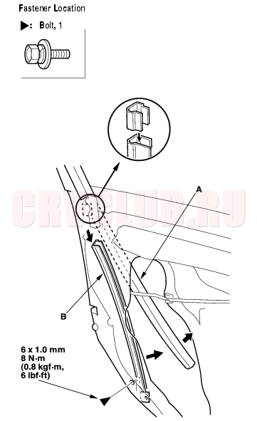
- Without Super locking and passenger's with Super Locking: Pull the glass run channel (A) away as necessary, and remove the bolt, then remove the center lower channel (B) by pulling it downward.
- Disconnect the outer handle rod and cylinder rod (see step 4 on page 20-12 ).
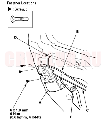
20-15
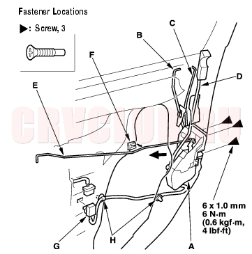
- Without Super Locking: Remove the latch (A). Take care not to bend the outer handle rod (B), cylinder rod (C), lock rod (D), and inner handle rod (E). The Honda Lock make is shown (the Mitsui make is similar).
- Release the inner handle rod from the rod holder (F).
- Disconnect the connectors (G).
- Remove the screws.
- Remove the latch from the hole in the door.
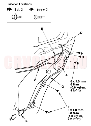
- With Super Locking: Remove the latch (A). Take care not to bend the outer handle rod (B), cylinder rod (C), lock rod (D), and inner handle rod (E).
- Release the inner handle rod from the rod holder (F).
- Disconnect the connector (G), and detach it. Detach the harness clips (H).
- Remove the screws.
- Remove the latch from the hole in the door.
- Install the latch in the reverse order of removal, and note these items:
- Make sure the actuator connector(s) is plugged in properly, and each rod is connected securely.
- Make sure the door locks and opens properly.
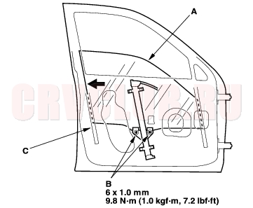
Front Door Glass and Regulator Replacement20-16
NOTE: Put on gloves to protect your hands.
- Remove these items:
- Door panel (see page 20-9)
- Plastic cover, as necessary (see page 20-2)
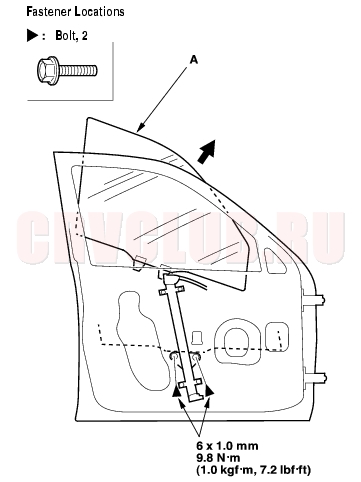
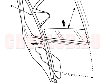
- Carefully move the glass (A) until you can see the bolts, then remove them. Carefully pull the glass out through the window slot. Take care not to drop the glass inside the door.
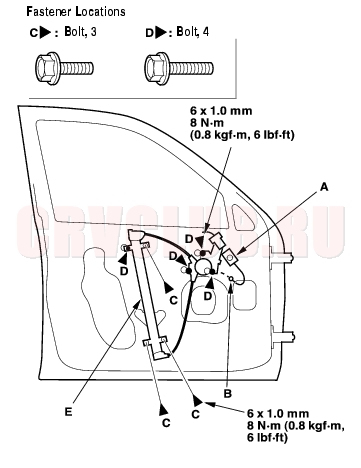
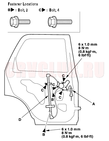
- Disconnect and detach the connector (A) and harness clip (B) from the door.
- Remove the bolts (C), and loosen the bolts (D), then remove the regulator (E) through the hole in the door.
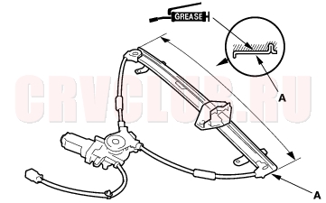
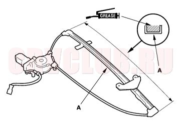
- Grease all the sliding surfaces of the regulator (A) where shown.
20-17
- Install the glass and regulator in the reverse order of removal, and note these items:
- Roll the glass up and down to see if it moves freely without binding.
- Make sure that there is no clearance between the glass and glass run channel when the glass is closed.
- Adjust the position of the glass as necessary (see page 20-34) .
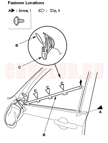
Front Door Glass Outer Weatherstrip Replacement20-17
Put on gloves to protect your hands. Take care not to scratch the door.
- Remove the power mirror (see page 20-39) .
To prevent scratching the power mirror and door, wrap the power mirror with a shop towel. Disconnecting the power mirror connector is not required.
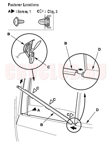
- Remove the screw (A) from the rear edge of the door. Starting at the rear, pry the door glass outer weatherstrip (B) up to detach the clips (C), then remove the weatherstrip.
- Install the weatherstrip in the reverse order of removal, and replace any damaged clips.
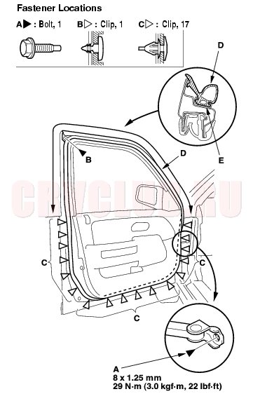
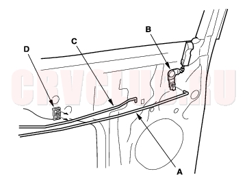
Front Door Weatherstrip Replacement20-18
Take care not to scratch the door. Use a clip remover to remove the clips.
- At the front pillar, remove the door stop mounting bolt (A).
- Detach the clips (B, C), then remove the door weatherstrip (D).
- Install the weatherstrip in the reverse order of removal, and note these items:
- Replace any damaged clips.
- Make sure the weatherstrip is installed in the holder (E) securely.
- Apply liquid thread lock to door stop mounting bolt before installation.
- Check for water leaks (see step 7 on page 20-35 ).
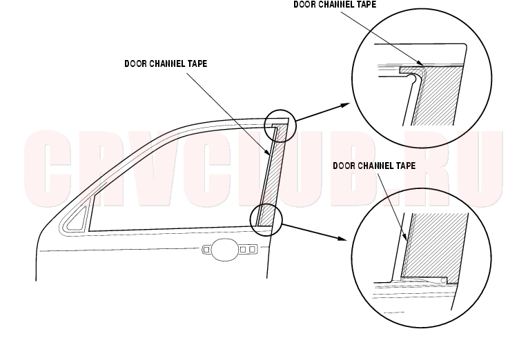
Front Door Channel Tape Replacement20-19
Keep dust away from the working area. When working at lower temperatures, heat the door channel and door channel tape with a hair dryer.
Door channel: about 15°C (59°F). Door channel tape: about 30°C (86°F). When heating the door channel tape, heat it evenly and gradually to prevent deformation. When pressing the door channel tape, slowly press it from the corner to prevent air bubbles and wrinkles. If there are air bubbles in the door channel tape, release the air with your finger or a plastic squeegee. If the air bubble is more than 10 mm (0.4 in.) in diameter, peel up the door channel tape, then reapply it.
- The following tools are required to replace the door channel tape:
- Plastic squeegee
- Alcohol
- Sponge or Shop towel
- Hair dryer
- Remove these items:
- Door glass outer weatherstrip (see page 20-17)
- Glass run channel, as necessary (see page 20-2)
- Slowly peel up the old door channel tape while heating it with a hair dryer.
- Clean the door channel bonding surface with a sponge dampened in alcohol. After cleaning, keep oil, grease, and water from getting on the surface.
- Attach the door channel tape.
- Peel the edge of the adhesive backing from the channel tape.
- Fit the door channel tape to the door channel.
- Apply the door channel tape to the door channel while peeling the adhesive backing from it a little at a time. Check that the channel tape is parallel with the door channel.
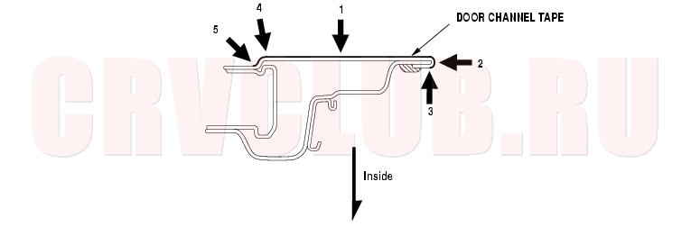
- Push firmly on the door channel tape with a plastic squeegee (felt side).
- NOTE: To prevent air bubbles, slowly press the door channel tape around the door frame corner.
- As necessary, repeat the preceding steps.
- Reinstall all remaining removed parts.
- Check that the body color on the door channel is covered by the door channel tape.
- Check for water leaks (see step 7 on page 20-35 ).
Front Door Channel Tape Replacement (cont'd)20-20
Attachment Point (Reference):
Note: Press in numbered sequence:
Rear Door Panel Removal/Installation20-21
Special Tools Required
Trim pad remover, Snap-on A 177A or equivalent, commercially available.
- Lower the glass fully.
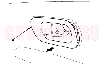
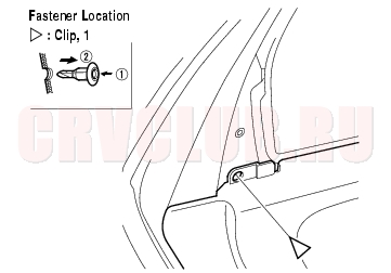
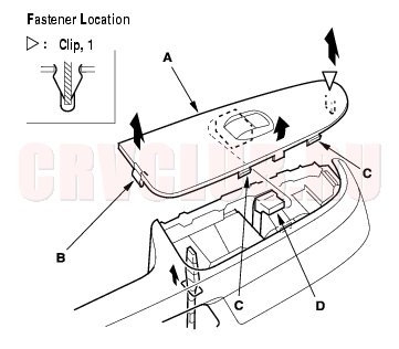
- Remove the inner handle (A). Take care not to scratch the door panel.
- Using a flat-tip screwdriver wrapped with protective tape, pry out on the upper portion of the cover (B) to release the hooks (C, D), then remove the cover.
- Remove the screws.
- Pull out the inner handle forward and out half-way to release the hook (E).
- Disconnect the inner handle rod (F).
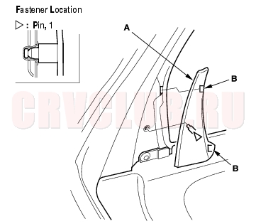
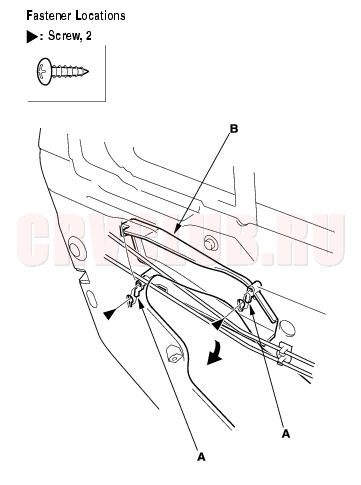
- Remove the door quarter inner trim (A). Take care not to scratch the door.
- Using a flat-tip screwdriver wrapped with protective tape, insert it next to the pin, and detach the pin by prying on the trim while holding the hock portions. Take care not to break the hooks (B).
- Pull the trim forward to release the hooks.
- Remove the clip from the door quarter inner trim mounting portion.
Rear Door Panel Removal/Installation (cont'd)20-22
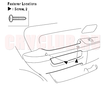
- Remove the screws from under the armrest.
- Remove the switch panel (A).
- Insert a flat-tip screwdriver wrapped with protective tape through a hole under the armrest, and push up the back of the panel to release the rear hook (B).
- Pull out along the edge of the panel to release the hooks (C) and clip.
- Disconnect the power window switch connector (D).
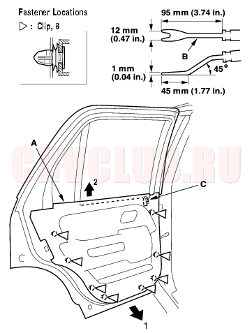
- Remove the door panel (A) with as little bending as possible to avoid creasing or breaking it.
- Release the clips that hold the door panel with a commercially available trim pad remover (B).
- Stating at the rear, pull the door panel upward, then release the lock knob (C).
20-23
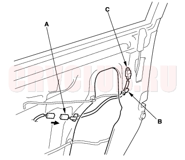
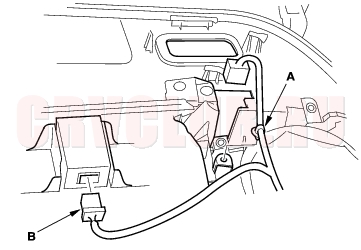
- Form the back of the door panel, detach the harness clip (A). If equipped, disconnect the super locking control unit connector (B). RHD is shown, LHD is symmetrical except it has no super locking control unit.
- Install the panel in the reverse order of removal, and note these items:
- Replace any damaged clips.
- Make sure the connector (s) is plugged in properly and the rod is connected properly.
Rear Door Outer Handle Replacement20-23
NOTE : Put on gloves to protect your hands.
- Remove these items:
- Door panel (see page 20-21)
- Plastic cover, as necessary (see page 20-6)
- Raise the glass fully.
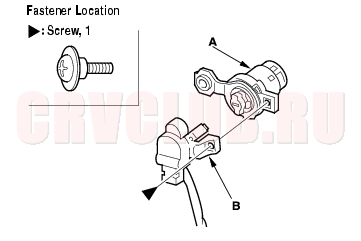
- Remove the screws, and release the hooks (A), then remove the rod protector (B).
Rear Door Outer Handle Replacement (cont'd)20-24
- Remove the access cap (A), then disconnect the outer handle rod (B).
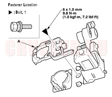
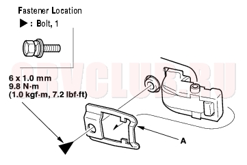
- Remove the bolt, then remove the protector (A).
- Remove the bolt, then remove the spacer (A).
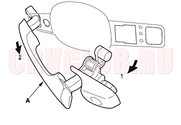
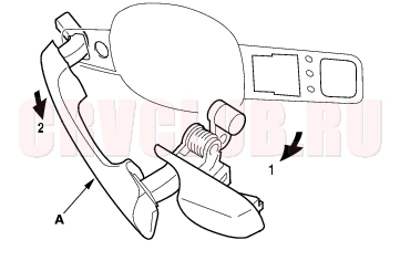
- While pulling the outer handle (A), remove the handle from the holes in the door panel.
Take care not to scratch the door.
- Install the handle in the reverse order of removal, and note these items:
- Make sure the outer handle rod is connected securely.
- Make sure the door locks and opens properly.
Rear Door Latch Replacement20-25
NOTE: Put on gloves to protect your hands.
- Remove these items:
- Door panel (see page 20-21)
- Plastic cover, as necessary (see page 20-6)
- Rod protector (see step 3 on page 20-23 )
- Raise the glass fully.
- Remove the access cap, than disconnect the outer handle rod (see step 4 on page 20-24 ).
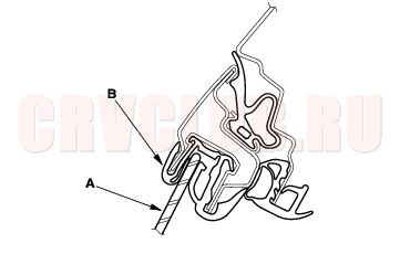
- Disconnect the lock rod (A) from the lock crank (B), and release the inner handle rod (C) and lock rod from the rod holder (D).
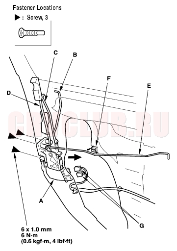
- Without Super Locking: Remove the latch (A). Take care not to bend the inner handle rod (B), lock rod (C), and outer handle rod (D). The Honda Lock make is shown (the Mitsui make is similar).
- Disconnect the connector (E).
- Remove the screws.
- Remove the latch from the hole in the door.
Rear Door Latch Replacement (cont'd)20-26
- With Super Locking: Remove the latch (A). Take care not to bend the inner handle rod (B), lock rod (C), and outer handle rod (D).
- Disconnect the connector (E), and detach it.
- Remove the bolts (F), then release the wire harness (G) from the door.
- Remove the screws (H)
- Remove the latch from the hole in the door.
- If necessary, remove the lock crank (A) from the door.
- Install the latch in the reverse order of removal, and note these items:
- Make sure the connector is plugged in properly, and each rod is connected securely.
- Make sure the door locks and opens properly.
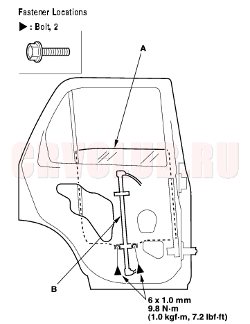
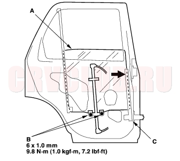
Rear Door Glass and Regulator Replacement20-27
NOTE: Put on gloves to protect your hands.
- Remove these items:
- Door panel (see page 20-21)
- Plastic cover, as necessary (see page 20-6)
- Rod protector (see step 3 on page 20-23 )
- Carefully move the glass (A) until you can see the bolts, then remove them. Remove the glass from the regulator (B), and carefully lower the glass. Take care not to drop the glass inside the door.
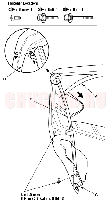
- Pull the glass run channel (A) away as needed. Pull back the door quarter glass seal (B), then remove the screw (C). Remove the bolts (D, E) securing the center channel (F), then remove the collar (G).
Rear Door Glass and Regulator Replacement (cont'd)20-28
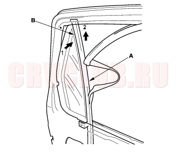
- Pull the upper portion of the center channel (A) forward to remove it from the door quarter glass seal (B), and pull up the center channel. Take care not to scratch the door.
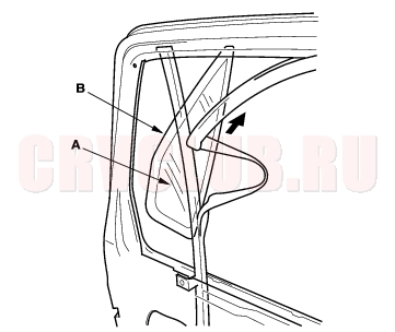
- Remove the door quarter glass (A) and seal (B) as an assembly from the door.
- Release the glass (A) from the center channel (B), and carefully remove the glass out though the window slot. Take care not to drop the glass inside the door.
20-29
- Disconnect and detach the connector (A) from the door.
- Remove the bolts (B), and loosen the bolts (C), then remove the regulator (D) through the hole in the door.
- Grease all the sliding surfaces of the regulator (A) where shown.
- Install the glass and regulator in the reverse order of removal, and note these items:
- Roll the glass up and down to see if it moves freely without binding.
- Make sure that there is no clearance between the glass and glass run channel when the glass is closed.
- Adjust the position of the glass as necessary (see page 20-34) .
Rear Door Glass Outer Weatherstrip Replacement20-30
Put on gloves to protect your hands. Take care not to scratch the door.
- Remove the screw (A) from the front edge of the door. Starting at the front, pry the door glass outer weatherstrip (B) up to detach the clips (C), and release the weatherstrip from the door quarter glass seal (D), then remove it.
- Install the weatherstrip in the reverse order of removal, and replace any damaged clips.
Rear Door Weatherstrip Replacement20-30
Take care not to scratch the door. Use a clip remover to remove the clips.
- At the center pillar, remove the door stop mounting bolt (A).
- Detach the clip (B, C), then remove the door weatherstrip (D).
- Install the weatherstrip in the reverse order of removal, and note these items:
- Replace any damaged clips.
- Make sure the weatherstrip is installed in the holder (E) securely.
- Apply liquid thread lock to the door stop mounting bolt before installation.
- Check for water leaks (see step 7 on page 20-35 ).
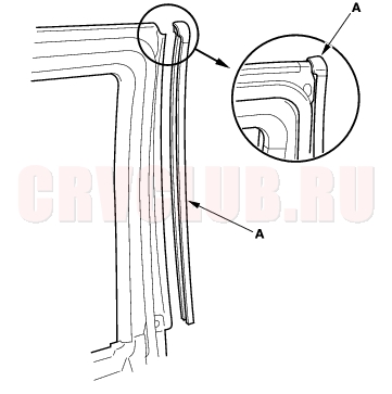
Rear Door Center Pillar Seal Replacement20-31
NOTE: Take care not to scratch the door.
- Pull the door center pillar seal (A) away, then remove it.
- After installing the seal to the upper edge of the door flange, align the seal to the bottom edge of the door flange, then push the seal into place.
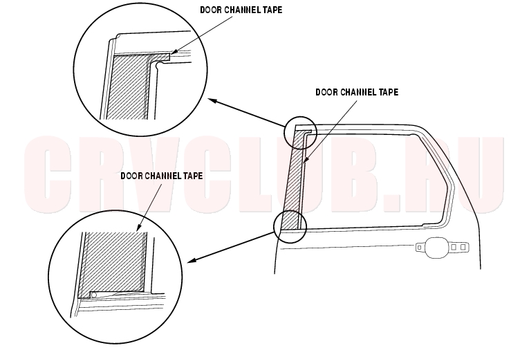
Rear Door Channel Tape Replacement20-32
Keep dust away from the working area. When working at lower temperatures, heat the door channel and door channel tape with a hair dryer.
Door channel: about 15°C (59°F). Door channel tape: about 30°C (86°F). When heating the door channel tape, heat it evenly and gradually to prevent deformation. When pressing the door channel tape, slowly press it from the corner to prevent air bubbles and wrinkles. If there are air bubbles in the door channel tape, release the air with your finger or a plastic squeegee. If the air bubble is more than 10 mm (0.4 in.) in diameter, peel up the door channel tape, then reapply it.
- The following tools are required to replace the door channel tape:
- Plastic squeegee
- Alcohol
- Sponge or Shop towel
- Hair dryer
- Remove these items:
- Door glass outer weatherstrip (see page 20-30)
- Glass run channel, as necessary (see page 20-6)
- Door center pillar seal (see page 20-31)
- Slowly peel up the old door channel tape while heating it with a hair dryer.
- Clean the door channel bonding surface with a sponge dampened in alcohol. After cleaning, keep oil, grease, and water from getting on the surface.
- Attach the door channel tape.
- Peel the edge of the adhesive backing from the channel tape.
- Fit the door channel tape to the door channel.
- Apply the door channel tape to the door channel while peeling the adhesive backing from it a little at a time. Check that the channel tape is parallel with the door channel.
- Push firmly on the door channel tape with a plastic squeegee (felt side).
- NOTE: To prevent air bubbles, slowly press the door channel tape around the door frame corner.
- As necessary, repeat the preceding steps.
- Reinstall all remaining removed parts.
- Check that the body color on the door channel is covered by the door channel tape.
- Check for water leaks (see step 7 on page 20-35 ).
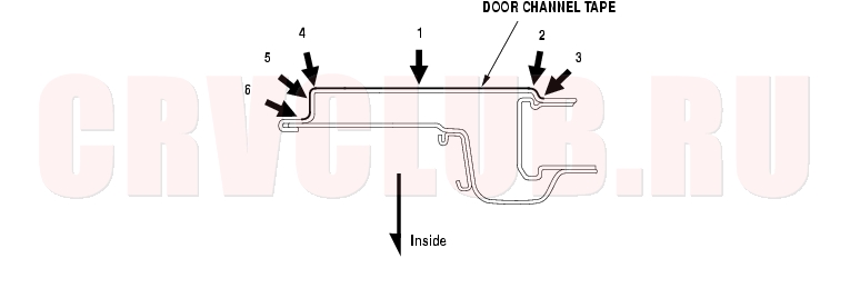
20-33
Attachment Point (Reference):
Note: Press in numbered sequence.
Front and Rear Door Glass Adjustment20-34
NOTE: Check the weatherstrips and glass run channel for damage or deterioration, and replace them if necessary.
- Place the vehicle on a firm, level surface.
- Remove these items:
- Door panel, front door (see page 20-9) , rear door (see page 20-21)
- Plastic cover, front door (see page 20-2) , rear door (see page 20-6)
- Carefully move the glass (A) until you can see the glass mounting bolts (B), then loosen them.
Front door:
Rear door:
- Push the glass (A) against the channel (C), then tighten the glass mounting bolts.
- Check that the glass moves smoothly.
- Raise the glass fully, and check for gaps. Also check that the glass (A) contacts the glass run channel (B) evenly.
20-35
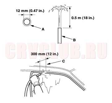
- Check for water leaks. Run water over the roof and on the sealing area as shown, and note these items:
- Use a 12 mm (0.47 in.) diameter hose (A).
- Adjust the rate of water flow as shown (B).
- Do not use a nozzle.
- Hold the hose about 300 mm (12 in.) away from the door (C).
- Attach the plastic cover, and install the door panel, front door (see page 20-9) , rear door (see page 20-21) .
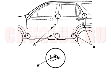
Front and Rear Door Position Adjustment20-36
SRS components are located in the center pillar bottom area. Review the SRS component locations (see page 23-14) , and the precautions and procedures (see page 23-16) in the SRS section before performing repairs or service.
NOTE: Check for a flush fit with the body, then check for equal gaps between the front, rear, and bottom door edges and the body. Check that the door and body edges are parallel. Before adjusting, replace the mounting bolts.
- Place the vehicle on a firm, level surface when adjusting the doors.
- Adjust at the hinges (A):
- Loosen the door mounting bolts (B) slightly, and move the door in or out until it's flush with the body.
- On the front door: Remove the front inner fender (see page 20-155) and front fender fairing (see page 20-156) . Loosen the hinge mounting bolts (C) slightly, and move the door backward or forward, up or down as necessary to equalize the gaps.
- On the rear door: Remove the center pillar lower trim panel (see page 20-76) , and remove the front seat belt and retractor (see page 23-4) , and the plug seal from the body. Loosen the hinge mounting nuts (D) slightly, and move the door backward or forward, up or down as necessary to equalize the gaps.
- Place a shop towel (E) on the jack (F) to prevent damage to the door when adjusting the door.
Front door:
Rear door:
20-37
- Check that the door and body edges are parallel. If necessary, adjust the door cushions (A) to make the rear of the doors flush with the body.
- Apply body paint to the hinge mounting bolts, and around the hinges.
- Check for water leaks (see step 7 on page 20-35 ).
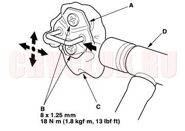
Front and Rear Door Striker Adjustment20-37
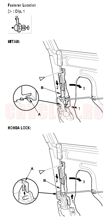
Make sure the door latches securely without slamming it. If necessary, adjust the striker (A): The striker nuts are fixed, but the striker can be adjusted slightly up or down, and in or out.
- Loosen the screws (B), then insert a shop towel (C) between the body and striker.
- Lightly tighten the screws.
- Wrap the striker with a shop towel, then adjust the striker by tapping it with a plastic hammer (D). Do not tap the striker too hard.
- Loosen the screws, and remove the shop towel.
- Lightly tighten the screws.
- Hold the outer handle out, and push the door against the body to be sure the striker allows a flush fit. If the door latches properly, tighten the screws and recheck.
|
Body20-1
Doors20-2 |