Valve Body14-205
|
A/T
Valve Body14-205 |
Valve Body14-205
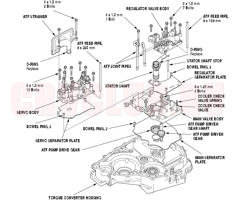
Valve Bodies and ATF Strainer Removal
Exploded View
NOTE: The illustration shows the 4WD transmission; the 2WD is similar.
Valve Bodies and ATF Strainer Removal (cont'd)14-206
NOTE: Refer to the Exploded View as needed during the following procedure.
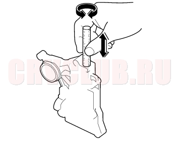
- Remove the ATF feed pipes from the regulator valve body, and servo body.
- Remove the ATF strainer (two bolts).
- Remove the servo body (13 bolts), then remove the separator plate and dowel pins (two).
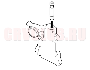
- Remove the ATF joint pipes (one bolt) from the regulator valve body.
- Remove the regulator valve body (seven bolts).
- Remove the stator shaft and stator shaft stop.
- Remove the regulator separator plate and dowel pins (two).
- Remove the cooler check valve spring and valve from the main valve body, then remove the main valve body (three bolts). Do not let the check balls fall out.
- Remove the ATF pump driven gear shaft, then remove the ATF pump gears.
- Remove the main separator plate and dowel pins (two).
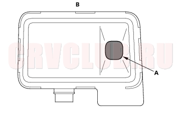
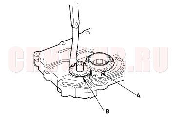
- Clean the inlet opening (A) of the ATF strainer (B) thoroughly with compressed air, then check that it is in good condition and that the inlet opening is not clogged.
- Test the ATF strainer by pouring clean ATF through the inlet opening, and replace it if it is clogged or damaged.
Valve Body Repair14-207
NOTE: This repair is only necessary if one or more of the valves in a valve body do not slide smoothly in their bores. Use this procedure to free the valves.
- Soak a sheet of #600 abrasive paper in ATF for about 30 minutes.
- Carefully tap the valve body so the sticking valve drops out of its bore. It may be necessary to use a small screwdriver to pry the valve free. Be careful not to scratch the bore with the screwdriver.
- Inspect the valve for any scuff marks. Use the ATF-soaked #600 paper to polish off any burrs that are on the valve, then wash the valve in solvent and dry it with compressed air.
- Roll up half a sheet of ATF-soaked #600 paper and insert it in the valve bore of the sticking valve.
Twist the paper slightly, so that it unrolls and fits the bore tightly, then polish the bore by twisting the paper as you push it in and out.
- NOTE: The valve body is aluminum and doesn't require much polishing to remove any burrs.
- Remove the #600 paper. Thoroughly wash the entire valve body in solvent, then dry it with compressed air.
- Coat the valve with ATF, then drop it into its bore. It should drop to the bottom of the bore under its own weight. If not, repeat step 4, then retest. If the valve still sticks, replace the valve body.
- Remove the valve, and thoroughly clean it and the valve body with solvent. Dry all parts with compressed air, then reassemble using ATF as a lubricant.
Valve Body Valve Installation14-208
- Coat all parts with ATF before assembly.
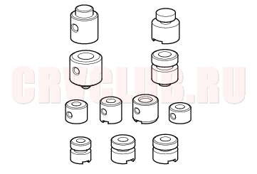
- Install the valves and springs in the sequence shown for the main valve body (see page 14-209) , regulator valve body (see page 14-211) , and servo body (see page 14-212) . Refer to the following valve cap illustrations, and install each valve cap so the end shown facing up will be facing the outside of the valve body.
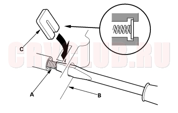
- Install all the springs and seats. Insert the spring (A) in the valve, then install the valve in the valve body (B). Push the spring in with a screwdriver, then install the spring seat (C).
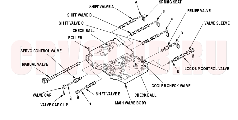
Main Valve Body Disassembly, Inspection, and Reassembly14-209
- Clean all parts thoroughly in solvent or carburetor cleaner, and dry them with compressed air. Blow out all passages.
- Do not use a magnet to remove the check balls, it may magnetize the balls.
- Inspect the valbe body for scoring and damage.
- Check all valves for free movement. If any fail to slide freely, refer to Valve Body Repair (see page 14-207) .
- Coat all parts with ATF during assembly.
ATF Pump Inspection14-210
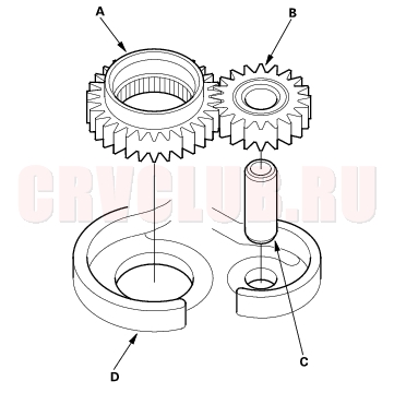
- Install the ATF pump drive gear (A), driven gear (B) and ATF pump driven gear shaft (C) in the main valve body (D). Lubricate all parts with ATF, and install the ATF pump driven gear with its grooved and chamfered side facing up.
- Measure the side clearance of the ATF pump drive gear (A) and driven gear (B).
ATF Pump Gears Side (Radial) Clearance:
Standard (New):
ATF Pump Drive Gear
0.210 - 0.265 mm (0.0083 - 0.0104 in.)
ATF Pump Driven Gear
0.070 - 0.125 mm (0.0028 - 0.0049 in.)
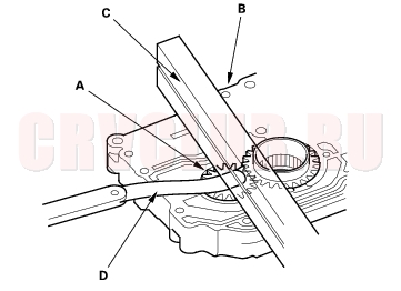
- Remove the ATF pump driven gear shaft. Measure the thrust clearance between the ATF pump driven gear (A) and the valve body (B) with a straight edge (C) and a feeler gauge (D).
ATF Pump Drive/Driven Gear Thrust (Axial) Clearance:
Standard (New):
0.03 - 0.05 mm (0.001 - 0.002 in.)
Service Limit:
0.07 mm (0.003 in.)
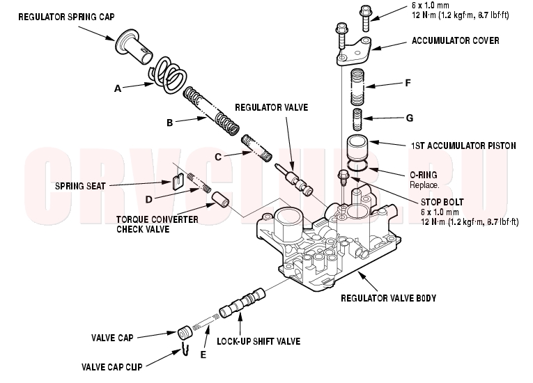
Regulator Valve Body Disassembly, Inspection, and Reassembly14-211
- Clean all parts thoroughly in solvent or carburetor cleaner, and dry them with compressed air. Blow out all passages.
- Inspect the valve body for scoring and damage.
- Check all valves for free movement. If any fail to slide freely, refer to Valve Body Repair (see page 14-207) .
- Hold the regulator spring cap in place while removing the stop bolt. The regulator spring cap is spring loaded. Once the stop bolt is removed, release the spring cap slowly so it does not pop out.
- Coat all parts with ATF during assembly.
- When reassembling the valve body, align the hole in the regulator spring cap with the hole in the valve body, then press the spring cap into the valve body, and tighten the stop bolt.
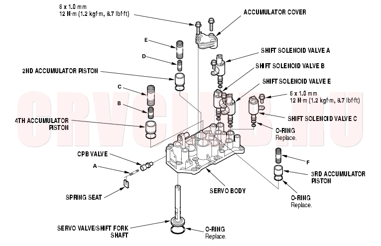
Servo Body Disassembly, Inspection, and Reassembly14-212
- Clean all parts thoroughly in solvent or carburetor cleaner, and dry them with compressed air. Blow out all passages.
- Inspect the valve body for scoring and damage.
- Check CPB valve for free movement. If any fail to slide freely, refer to Valve Body Repair (see page 14-207) .
- Do not hold the shift solenoid valve connector to remove and install it. Be sure to hold the shift solenoid valve body. When installing the shift solenoid vales, refer to Shift Solenoid Valves Installation (see page 14-213) .
- Coat all parts with ATF during assembly.
- Replace the O-rings with new one.
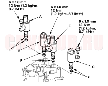
Shift Solenoid Valves Installation14-213
Do not install the shift solenoid valve B before installing the shift solenoid valve E. If solenoid valve B is installed before solenoid valves E, it may damage to hydraulic control system. Do not hold the shift solenoid valve connector to install it. Be sure to hold the shift solenoid valve body.
- Install the new O-rings (F) on each shift solenoid valves.
- NOTE: The new shift solenoid valve is equipped with the new O-rings. If you install the new shift solenoid valve, it is no need to replace the new O-rings on it.
- Install the shift solenoid valve A with holding the shift solenoid valve body, be sure to install the solenoid valve A until its mounting bolt bracket contacts to the servo body.
- Install the shift solenoid valve E with holding the shift solenoid valve body, be sure to install the solenoid valve E until its mounting bolt bracket contacts to the servo body.
- Install the shift solenoid valve B with holding the shift solenoid valve body, be sure to install the solenoid valve B until its mounting bolt bracket contacts to the bracket of the shift solenoid valve E.
- Install the shift solenoid valve C with holding the shift solenoid valve body, be sure to install the solenoid valve C until its mounting bolt bracket contacts to the servo body.
|
A/T
Valve Body14-205 |