Valve Body14-252
|
A/T
Valve Body14-252 |
Valve Body14-252
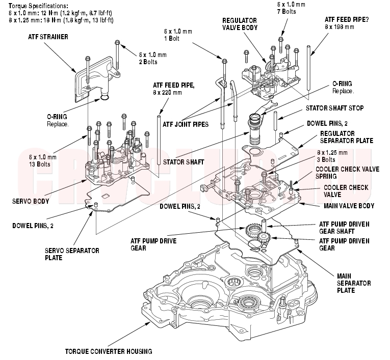
Valve Bodies and ATF Strainer Installation
Exploded View
NOTE: The illustration shows the 4WD transmission; the 2WD is similar.
14-253
NOTE: Refer to the Exploded View as needed during the following procedure.
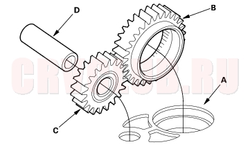
- Install the main separator plate (A) and two dowel pins on the torque converter housing. Then install the ATF pump drive gear (B), driven gear (C), and ATF pump driven gear shaft (D). Install the ATF pump driven gear with its grooved and chamfered side facing down.
- Install the main valve body.
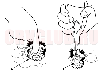
- Make sure the ATF pump drive gear (A) rotates smoothly in the normal operating direction, and the ATF pump driven gear shaft (B) moves smoothly in the axial and normal operating direction.
- If the ATF pump drive gear and ATF pump driven gear shaft do not move smoothly, loosen the main valve body bolts. Realign the ATF pump driven gear shaft, and retighten the bolts to the specified torque, then recheck. Failure to align the ATF pump driven gear shaft correctly will result in a seized ATF pump drive gear or ATF pump driven gear shaft.
- Make sure that the check balls (two) are in the main valve body, and install the cooler check valve spring and the cooler check valve.
- Install the regulator separator plate and dowel pins (two) on the main valve body.
- Install the stator shaft and stator shaft stop.
- Install the regulator valve body (seven bolts).
- Install the servo separator plate and dowel pins (two) on the main valve body.
- Install the servo body (13 bolts).
- Install the ATF strainer (two bolts).
- Install the ATF joint pipes (one bolt).
- Install the ATF feed pipes in the regulator valve body and servo body.
|
A/T
Valve Body14-252 |