Shafts and Clutches14-218
|
A/T
Shafts and Clutches14-218 |
Shafts and Clutches14-218
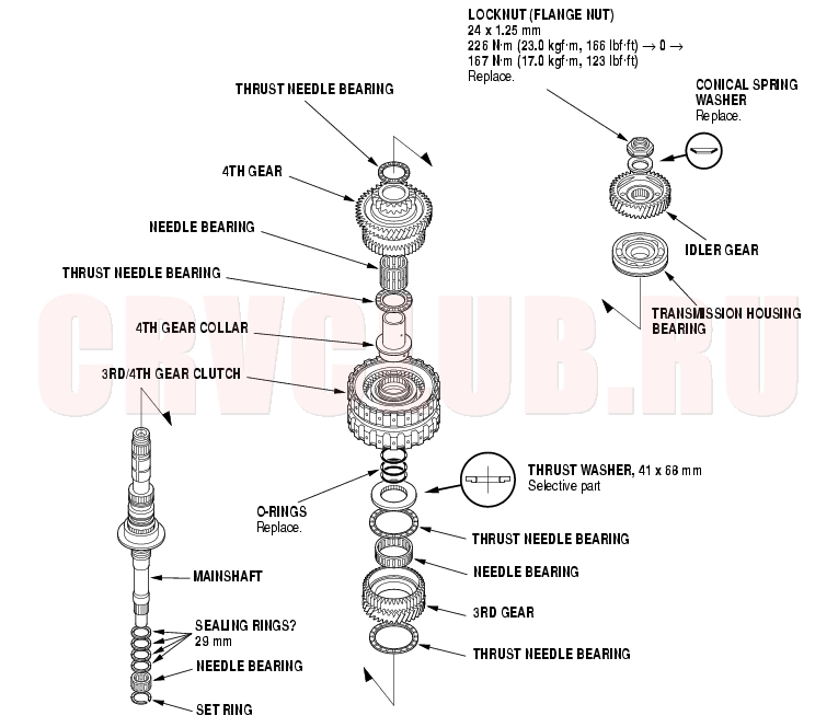
Mainshaft Disassembly, Inspection and Reassembly
- Inspect the thrust needle bearing and the needle bearing for galling and rough movement.
- Inspect the splines for excessive wear and damage.
- Check shaft bearing surface for scoring and excessive wear.
- Before installing the O-rings, wrap the shaft splines with tape to prevent O-ring damage.
- Lubricate all parts with ATF during assembly.
- Install the conical spring washer, 41 x 68 mm thrust washer in the direction shown.
- Replace the locknut and conical spring washer with new ones when assembling the transmission.
- Check the clearance of the 3rd gear.
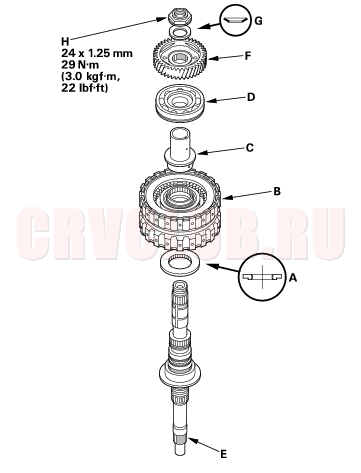
Mainshaft 3rd Gear Clearance Inspection14-219
- Remove the mainshaft transmission housing bearing (see page 14-202) .
- Assemble 41 x 68 mm thrust washer (A), 3rd/4th clutch (B), 4th gear collar (C), and transmission housing bearing (D) on the mainshaft (E). Do not install the O-rings during inspection.
- Install the idler gear (F) on the mainshaft by a press, then install the conical spring washer (G) and locknut (H).
- Tighten the locknut to 29 N·m (3.0 kgf·m, 22 lbf·ft).
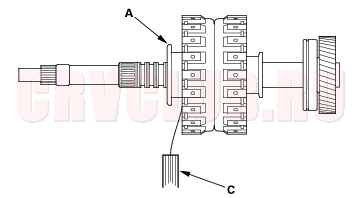
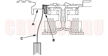
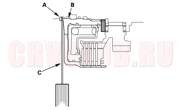
- Measure the clearance between the mainshaft flange (A) and 41 x 68 mm thrust washer (B) with a feeler gauge (C), in at least three places. Use the average as the actual clearance.
STANDARD: 0.03 - 0.11 mm (0.001 - 0.004 in.)
Mainshaft 3rd Gear Clearance Inspection (cont'd)14-220
- If the clearance is out of standard, remove the 41 x 68 mm thrust washer and measure its thickness.
- Select and install a new thrust washer, then recheck.
- After replacing the thrust washer, make sure the clearance is within standard.
- Disassemble the shaft and gears.
- Reinstall the bearing in the transmission housing (see page 14-203) .
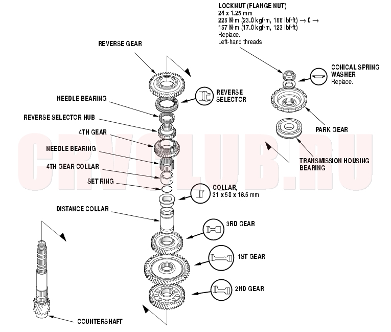
Countershaft Disassembly, Inspection and Reassembly14-221
K20A4 and K20A5 Engine Models
- Inspect the thrust needle bearing and the needle bearing for galling and rough movement.
- Inspect the splines for excessive wear and damage.
- Check shaft bearing surface for scoring and excessive wear.
- Lubricate all parts with ATF during assembly.
- Install the conical spring washer, reverse selector, 31 x 50 x 18.5 mm collar, 3rd gear, 1st gear, and 2nd gear in the direction shown.
- Countershaft locknut has left-hand threads.
- Replace the locknut and conical spring washer with new ones when assembling the transmission.
- Some reverse selector hubs and 4th gear collars are press-fitted to the countershaft; special tools are needed to remove them (see page 14-223) and install them (see page 14-224) .
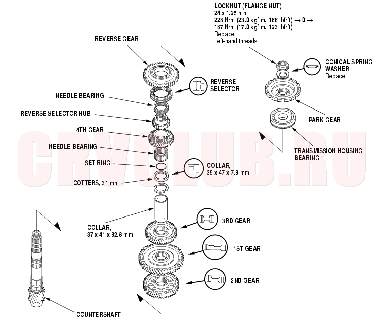
Countershaft Disassembly, Inspection and Reassembly (cont'd)14-222
K24A1 Engine Model
- Inspect the thrust needle bearing and the needle bearing for galling and rough movement.
- Inspect the splines for excessive wear and damage.
- Check shaft bearing surface for scoring and excessive wear.
- Lubricate all parts with ATF during assembly.
- Install the conical spring washer, reverse selector, 31 x 47 x 7.8 mm collar, 3rd gear, 1st gear, and 2nd gear in the direction shown.
- Countershaft locknut has left-hand threads.
- Replace the locknut and conical spring washer with new ones when assembling the transmission.
- Some reverse selector hubs are press-fitted to the countershaft; special tools are needed to remove them (see page 14-225) and install them (see page 14-226) .
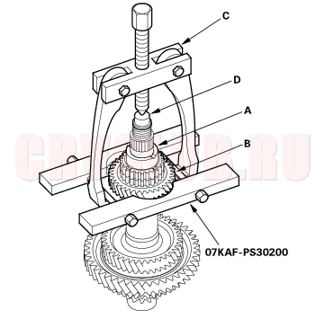
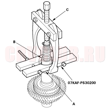
Selector Hub and 4th Gear Collar Removal14-223
Special Tools Required
Bearing separator 07KAF-PS30200
K20A4 and K20A5 Engine Models
Some reverse selector hubs and 4th gear collars are not press-fitted, and can be removed without using the special tool and a puller. Place a shaft protector between the countershaft and a puller to prevent damaging the countershaft.
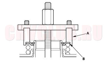
- Remove the reverse selector hub (A) and 4th gear (B) with the special tool, a two-jaw (or three-jaw) puller (C), and a shaft protector (D).
- Install the special tool with inserting it to the opening between 31 x 50 x 18.5 mm collar (A) and 4th gear collar (B). Set the puller (C) to the special tool, then remove the 4th gear collar.
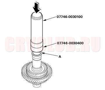
Selector Hub and 4th Gear Collar Installation14-224
Special Tools Required
Driver 40 mm I.D. 07746-0030100 Driver attachment, 35 mm I.D. 07746-0030400 K20A4 and K20A5 Engine Models
NOTE: Some reverse selector hubs and 4th gear collars are not press-fitted, and can be installed without using the special tools and a press.
- Assemble the 2nd gear, 1st gear, 3rd gear, distance collar, and 31 x 50 x 18.5 mm collar on the countershaft, and secure them with the set ring (see page 14-221) .
- Install the 4th gear collar (A) with the special tools and a press.
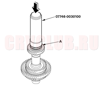
- Install the needle bearing and 4th gear.
- Install the reverse selector hub (A) with the special tool and a press.
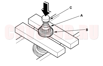
Reverse Selector Hub and 1st Gear Removal14-225
K24A1 Engine Model
- Remove the reverse selector hub (A) and the 4th gear (B) from the countershaft with a press. Place a shaft protector (C) between the countershaft and press to prevent damaging the countershaft.
- NOTE: Some reverse selector hubs are not press-fitted, and can be removed without using a press.
- Remove the needle bearing, set ring, 35 x 47 x 7.8 mm collar, 31 mm cotters, and 37 x 41 x 82.8 mm collar from the countershaft.
- Remove the 1st gear (A) and 3rd gear (B) from the countershaft with a press. Place a shaft protector (C) between the countershaft and press to prevent damaging the countershaft.
- Remove the 2nd gear from the countershaft by hand.
Reverse Selector Hub and 1st Gear Installation14-226
Special Tools Required
Driver 40 mm I.D. 07746-0030100
K24A1 Engine Model
- Apply ATF to the parts.
- Install the 2nd gear to the countershaft by hand.
- Align the shaft splines with those on 1st gear, then press the countershaft (A) into the 1st gear (B) with a press. Place a shaft protector (C) between the countershaft and press to prevent damaging the contershaft.
- Stop pressing the countershaft when the 1st gear contacts the 2nd gear (D).
- Install the 3rd gear, 37 x 41 x 82.8 mm collar, 31 mm cotters, 35 x 47 x 7.8 mm collar, set ring, needle bearing, and 4th gear on the countershaft.
- Slide the reverse selector hub (A) over the countershaft (B), then press it in place with the special tool and a press.
- NOTE: Some reverse selector hubs are not press-fitted, and can be installed without using the special tool and a press.
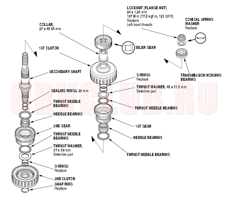
Secondary Shaft Disassembly, Inspection and Reassembly14-227
NOTE: The illustration shows the K20A4 and K20A5 engine models; the K24A1 engine model is similar.
- Inspect the thrust needle bearing and the needle bearing for galling and rough movement.
- Inspect the splines for excessive wear and damage.
- Check shaft bearing surface for scoring and excessive wear.
- Before installing the O-rings, wrap the shaft splines with tape to prevent O-ring damage.
- Lubricate all parts with ATF during assembly.
- Install the conical spring washer, idler gear in the direction shown.
- Secondary shaft locknut has left-hand threads.
- Replace the locknut and conical spring washer with new ones when assembling the transmission.
- Check the clearance of the 2nd and 1st gears.
Secondary Shaft Ball Bearing, Idler Gear Removal and Installation14-228
Special Tools Required
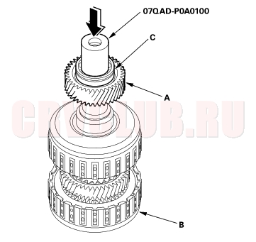
Driver attachment, 42 mm I.D. 07QAD-P0A0100
NOTE: The illustration shows the K20A4 and K20A5 engine models; the K24A1 engine model is similar.
Removal
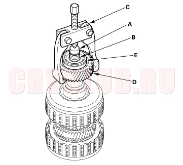
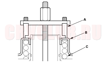
- Place a shaft protector (A) on the secondary shaft (B), and set the puller (C) to the idler gear (D), then remove the idler gear and ball bearing (E).
Installation
- Install the idler gear (A) on the secondary shaft (B), and install the ball bearing (C) over the idler gear with the special tool and a press.
Secondary Shaft 2nd Gear Clearance Inspection14-229
NOTE: The illustration shows the K20A4 and K20A5 engine models; the K24A1 engine model is similar.
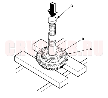
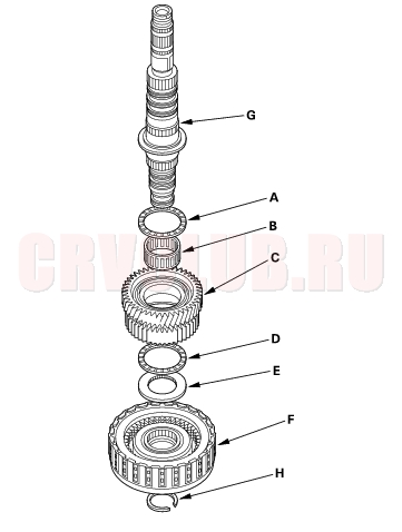
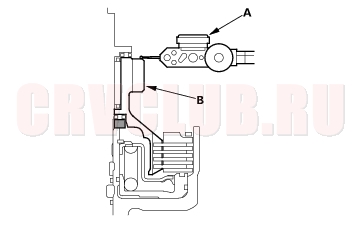
- Install the thrust needle bearing (A), needle bearing (B), 2nd gear (C), thrust needle bearing (D), 37 x 58 mm thrust washer (E), and 2nd clutch (F) on the secondary shaft (G), then secure them with the snap ring (H).
- Measure the clearance between the snap ring (A) and the 2nd clutch guide (B) with a feeler gauge (C), in at least three places. Use the average as the actual clearance.
STANDARD: 0.04 - 0.12 mm (0.002 - 0.005 in.)
Secondary Shaft 2nd Gear Clearance Inspection (cont'd)14-230
- If the clearance is out of standard, remove the 37 x 58 mm thrust washer and measure its thickness.
- Select and install a new thrust washer, then recheck.
- After replacing the thrust washer, make sure the clearance is within standard.
- Disassemble the shaft and gears.
Secondary Shaft 1st Gear Clearance Inspection14-231
Special Tools Required
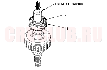
Driver attachment, 42 mm I.D. 07QAD-P0A0100
NOTE: The illustration shows the K20A4 and K20A5 engine models; the K24A1 engine model is similar.
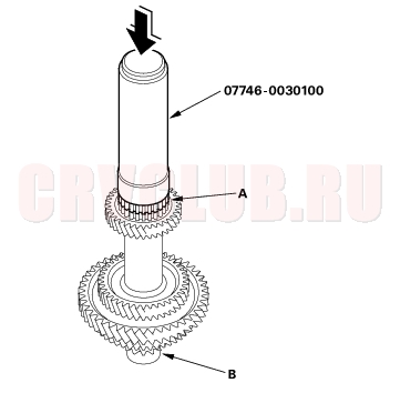
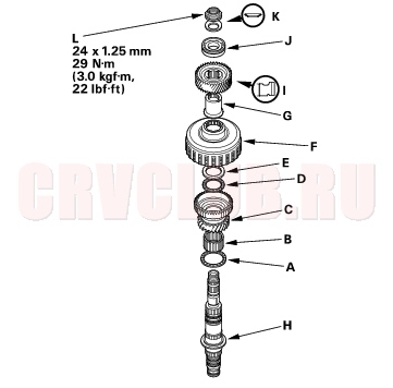
- Install the thrust needle bearing (A), needle bearing (B), 1st gear (C), thrust needle bearing (D), 40 x 51.5 mm thrust washer (E), 1st clutch (F), and 27 x 45 x 44 mm collar (G) on the secondary shaft (H).
- Install the idler gear (I), then install the ball bearing (J) on the idler gear with the special tool and a press.
- Install the conical spring washer (K) and locknut (L), then tighten the locknut to 29 N·m (3.0 kgf·m, 22 lbf·ft).
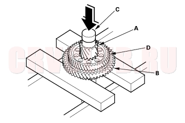
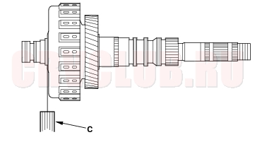
- Turn the secondary shaft assembly upside down, and set the dial indicator (A) on the 1st gear (B).
Secondary Shaft 1st Gear Clearance Inspection (cont'd)14-232
- Hold the secondary shaft, and measure the 1st gear axial clearance in at least three places while moving the 1st gear (A). Use the average as the actual clearance.
STANDARD: 0.04 - 0.12 mm (0.002 - 0.005 in.)
- If the clearance is out of standard, remove the 40 x 51.5 mm thrust washer and measure its thickness.
- Select and install a new thrust washer, then recheck.
- After replacing the thrust washer, make sure the clearance is within standard.
- Disassemble the shaft and gears.
Idler Gear Shaft Removal and Installation14-233
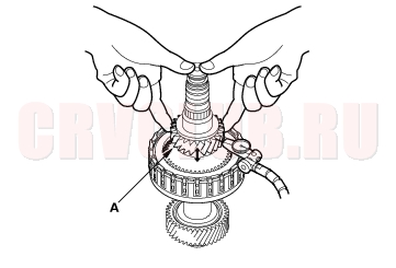
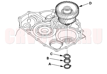
- Remove the snap ring (A), cotter retainer (B), and cotter keys (C). Do not distort the snap ring.
- Remove the idler gear shaft/idler gear assembly (D) from the transmission housing.
- Check the snap rings and cotter retainer for wear and damage. Replace them if they are worn, distorted, or damaged.
- Install the idler gear and shaft in the reverse order of removal.
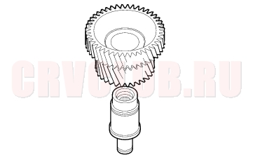
Idler Gear/Idler Gear Shaft Replacement14-234
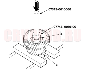
Special Tools Required
Handle driver 07749-0010000 Driver attachment, 32 x 35 mm 07746-0010100
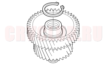
- Remove the snap ring from the idler gear/idler shaft assembly.
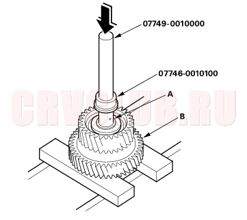
- Remove the idler gear shaft (A) from the idler gear (B) with the special tools and a press.
- Replace the idler gear or idler gear shaft, and attach the idler gear shaft to the idler gear.
- Install the idler gear shaft (A) in the idler gear (B) with the special tools and a press.
- Install the snap ring.
Clutch Disassembly14-235
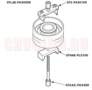
Special Tools Required
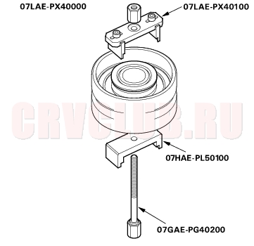
Clutch spring compressor set 07LAE-PX40000
Clutch spring compressor attachment
07LAE-PX40100Clutch spring compressor attachment
07HAE-PL50100Clutch spring compressor bolt assembly
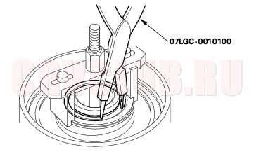
07GAE-PG40200Snap ring pliers 07LGC-0010100
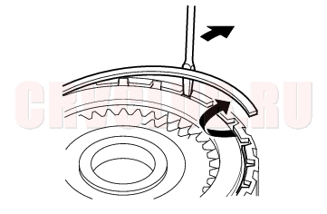
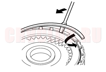
- Remove the snap ring with a screwdriver.
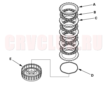
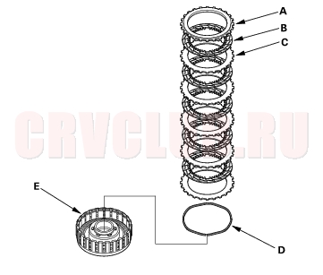
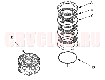
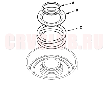
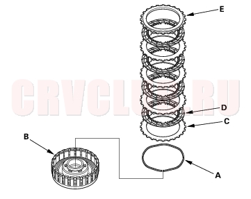
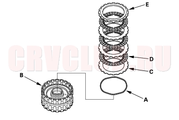
- Disassemble the 1st clutch of K20A4 and K20A5 engine models: Remove the clutch end plate (A), clutch discs (4) (B), clutch waved-plates (4) (C), and waved spring (D) from the 1st clutch drum (E).
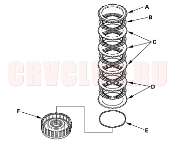
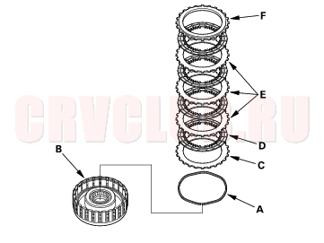
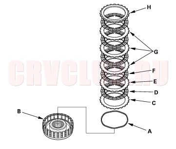
- Disassemble the 2nd clutch of K20A4 and K20A5 engine models: Remove the clutch end plate (A), clutch discs (4) (B), clutch waved-plates (3) (C), clutch flat-plate (D), and waved spring (E) from the 2nd clutch drum (F).
- Make a reference mark on the clutch flat plate (D).
Clutch Disassembly (cont'd)14-236
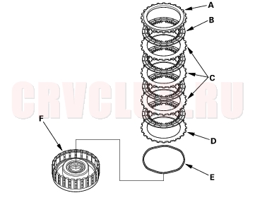
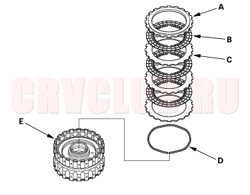
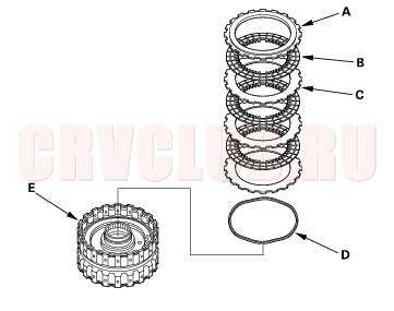
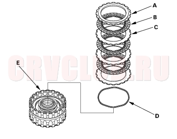
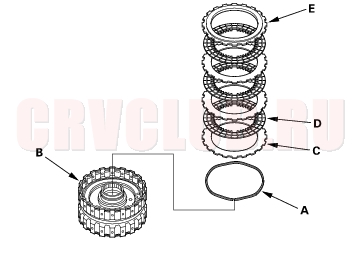
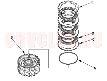
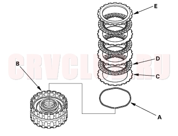
- Disassemble the 3rd clutch of K20A4 and K20A5 engine models: Remove the clutch end plate (A), clutch discs (3) (B), clutch waved-plates (3) (C), and waved spring (D) from the 3rd clutch drum (E).
- Disassemble the 4th clutch of K20A4 and K20A5 engine models: Remove the clutch end plate (A), clutch discs (3) (B), clutch waved-plates (3) (C), and waved spring (D) from the 4th clutch drum (E).
- Disassemble the 1st clutch of K24A1 engine model: Remove the clutch end plate (A), clutch discs (5) (B), clutch waved-pates (5) (C), and waved spring (D) from the 1st clutch drum (E).
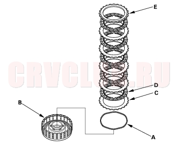
- Disassemble the 2nd clutch of K24A1 engine model: Remove the clutch end plate (A), clutch discs (5) (B), clutch waved-plates (3) (C), clutch flat-plates (2) (D), and waved spring (E) from the 2nd clutch drum (F).
- Make reference marks on the clutch flat-plates (D).
14-237
- Disassemble the 3rd clutch of K24A1 engine model: Remove the clutch end plate (A), clutch discs (3) (B), clutch waved-plates (3) (C), and waved spring (D) from the 3rd clutch drum (E).
- Disassemble the 4th clutch of K24A1 engine model: Remove the clutch end plate (A), clutch discs (3) (B), clutch waved-plates (3) (C), and waved spring (D) from the 4th clutch drum (E).
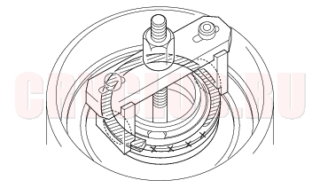
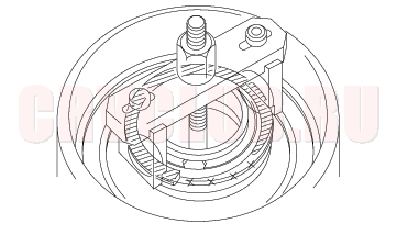
- Install the special tools.
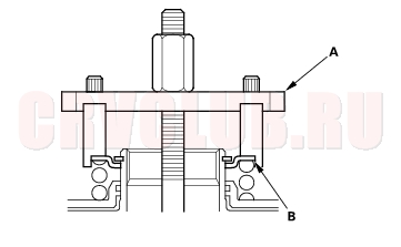
- Be sure the special tool (A) is adjusted to have full contact with the spring retainer (B) on the 3rd and 4th clutches.
Clutch Disassembly (cont'd)14-238
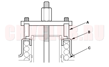
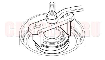
- Set the special tool (A) on the spring retainer (B) of the 1st and 2nd clutches in such a way that the special tool works on the clutch return spring (C).
- If either end of the special tool is set over an area of the spring retainer which is unsupported by the return spring, the retainer may be damaged.
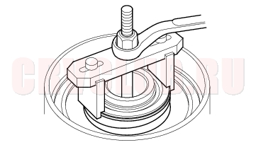
- Compress the return spring until the snap ring can be removed.
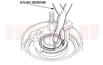
- Remove the snap ring with snap ring pliers.
- Remove the special tools.
14-239
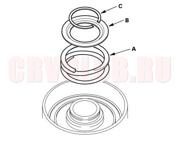
- Remove the snap ring (A), spring retainer (B), and return spring (C).
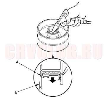
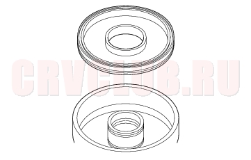
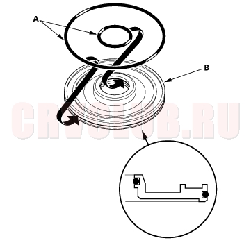
- Wrap a shop rag around the clutch drum (A), and apply air pressure to the fluid passage to remove the piston (B). Place a finger tip on the other passage while applying air pressure.
- Remove the piston, then remove the O-rings from the 3rd and 4th clutch pistons.
- Remove the piston, then remove the O-ring from the 1st and 2nd clutch drum, and remove the O-ring from each clutch piston.
Clutch Inspection14-240
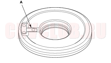
- Inspect the 3rd and 4th clutch pistons and clutch piston check valves.
- If the clutch piston check valve is loose or damaged, replace the clutch piston.
- Check the spring retainer for wear and damage.
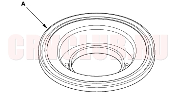
- Check the oil seal on the spring retainer of the 1st and 2nd clutches for wear, damage, and peeling.
- If the oil seal is worn, damaged, or peeling, replace the spring retainer.
- Inspect the clutch discs, clutch plates, and clutch end plate for wear, damage, and discoloration.
Standard Thickness
Clutch Discs: 1.94 mm (0.076 in.)
Clutch Plates:
K20A4 and K20A5 engines
All plates: 2.00 mm (0.079 in.)
K24A1 engine
1st clutch plates: 1.6 mm (0.063 in.)
2nd clutch plates: 2.0 mm (0.079 in.)
3rd and 4th clutch plates: 2.3 mm (0.091 in.)
- If the clutch discs are worn or damaged, replace them as a set. If the clutch discs are replaced, inspect the clutch end plate-to-top disc clearance.
- If any plate is worn, damaged, or discolored, replace the damaged plate with the new plate, and inspect the other waved-plates for a phase difference. If the clutch plate is replaced, inspect the clutch end plate-to-top disc clearance.
- If the clutch end plate is worn, damaged, or discolored, inspect the clutch end plate-to-top disc clearance, then replace the clutch end plate.
Clutch Waved-plate Phase Difference Inspection14-241
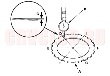
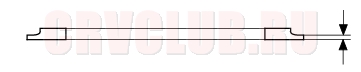
- Place the clutch waved-plate (A) on a surface plate, and set a dial indicator (B) on the waved-plate.
- Find the bottom (D) of a phase difference of the waved-plate, zero the dial indicator and make a reference mark on the bottom of the waved-plate.
- Rotate the 1st (K24A1 engine model) and 2nd clutch waved-plate about 60-degree apart from the bottom with holding the waved-plate by its circumference, and rotate the 1st (K20A4 and K20A5 engine models), 3rd, and 4th clutch waved-plate about 72-degree or 54-degree apart from the bottom. There will be presented a top (E) of a phase difference. Do not rotate the waved-plate with holding its surface, always rotate it with holding its circumference.
- Read the dial indicator. The dial indicator reads the phase difference (C) of the waved-plate between bottom and top.
Standard: 0.05 mm (0.002 in.) minimum
- Rotate the 1st (K24A1 engine model) and 2nd clutch waved-plate about 60-degree apart from the top, and rotate the 1st (K20A4 and K20A5 engine models), 3rd, and 4th clutch waved-plate 54-degree or 72-degree apart from the top. The dial indicator should be at the bottom of a phase difference (F and H), and zero the dial indicator.
- Measure the phase difference at the other two tops (G and I) of the waved-plate by following steps 3 thru 5.
- If the two values of the three measurements are within the standard, the waved-plate is OK. If the two values of the three measurements are out of the standard, replace the waved-plate.
Clutch Clearance Inspection14-242
Special Tools Required
Clutch compressor attachment 07ZAE-PRP0100
- Inspect the clutch piston, discs, plates, and end plate for wear and damage (see page 14-240) , and inspect clutch waved-plate phase difference (see page 14-241) , if necessary.
- Install the clutch piston in the clutch drum. Do not install the O-rings during inspection.
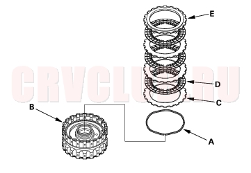
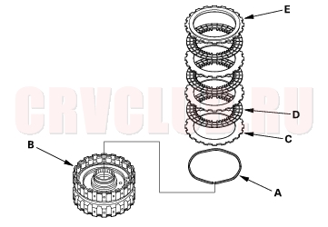
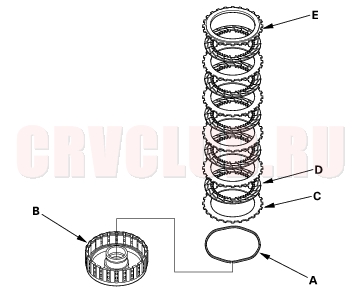
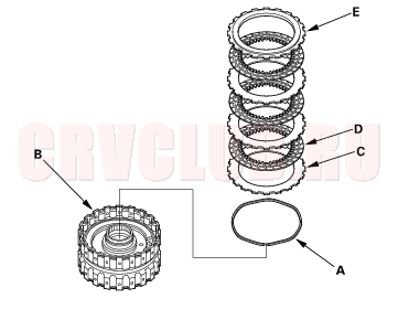
- Assemble the 1st clutch of K20A4 and K20A5 engine models: Install the waved spring (A) in the 1st clutch drum (B). Starting with the clutch waved-plate, alternately install the clutch plates (4) (C) and discs (4) (D), then install the clutch end plate (E) with the flat side toward the disc.
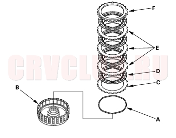
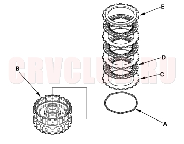
- Assemble the 2nd clutch of K20A4 and K20A5 engine models: Install the waved spring (A) in the 2nd clutch drum (B). Install the clutch flat-plate (C), then starting with the clutch disc, alternately install the clutch discs (4) (D) and waved-plates (3) (E), then install the clutch end plate (F) with the flat side toward the disc.
14-243
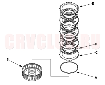
- Assemble the 3rd clutch of K20A4 and K20A5 engine models: Install the waved spring (A) in the 3rd clutch drum (B). Starting with the clutch waved-plate, alternately install the clutch plates (3) (C) and discs (3) (D), then install the clutch end plate (E) with the flat side toward the disc.
- Assemble the 4th clutch of K20A4 and K20A5 engine models: Install the waved spring (A) in the 4th clutch drum (B). Starting with the clutch waved-plate, alternately install the clutch plates (3) (C) and discs (3) (D), then install the clutch end plate (E) with the flat side toward the disc.
- Assemble the 1st clutch of K24A1 engine model: Install the waved spring (A) in the 1st clutch drum (B). Starting with the clutch waved-pate, alternately install the clutch plates (5) (C) and discs (5) (D), then install the clutch end plate (E) with the flat side toward the disc.
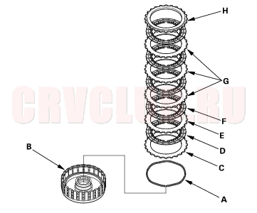
- Assemble the 2nd clutch of K24A1 engine model: Install the waved spring (A) in the 2nd clutch drum (B). Install the clutch flat-plate (C), clutch disc (D), and clutch flat-plate (E). Starting with the clutch disc, alternately install the clutch discs (4) (F) and clutch waved-pates (3) (G), then install the clutch end plate (H) with the flat side toward the disc.
Clutch Clearance Inspection (cont'd)14-244
- Assemble the 3rd clutch of K24A1 engine model: Install the waved spring (A) in the 3rd clutch drum (B). Starting with the clutch waved-plate, alternately install the clutch plates (3) (C) and discs (3) (D), then install the clutch end plate (E) with the flat side toward the disc.
- Assemble the 4th clutch of K24A1 engine model: Install the waved spring (A) in the 4th clutch drum (B). Starting with the clutch waved-plate, alternately install the clutch plates (3) (C) and discs (3) (D), then install the clutch end plate (E) with the flat side toward the disc.
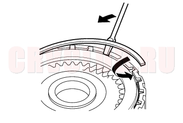
- Install the snap ring with a screwdriver.
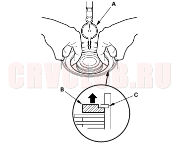
- Set a dial indicator (A) on the clutch end plate (B).
- Zero the dial indicator with the clutch end plate lifted up to the snap ring (C).
14-245
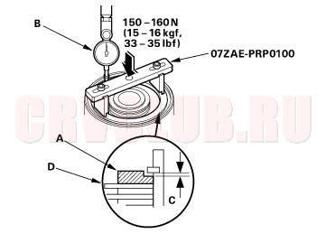
- Release the clutch end plate to lower the clutch end plate, then put the special tool on the end plate (A).
- Press the special tool down with 150 - 160 N (15 - 16 kgf, 33 - 35 lbf) using a force gauge, and read the dial indicator (B). The dial indicator reads the clearance (C) between the clutch end plate and top disc (D). Take measurements in at least three places, and use the average as the actual clearance.
Clutch End Plate-to-Top Disc Clearance
Service Limit:
K20A4 and K20A5 engine models
1st Clutch: 1.23 - 1.43 mm (0.048 - 0.056 in.)
2nd Clutch: 0.75 - 0.95 mm (0.030 - 0.037 in.)
3rd Clutch: 0.73 - 0.93 mm (0.029 - 0.037 in.)
4th Clutch: 0.73 - 0.93 mm (0.029 - 0.037 in.)
K24A1 engine model
1st Clutch: 1.28 - 1.48 mm (0.050 - 0.058 in.)
2nd Clutch: 0.85 - 1.05 mm (0.033 - 0.041 in.)
3rd Clutch: 0.73 - 0.93 mm (0.029 - 0.037 in.)
4th Clutch: 0.73 - 0.93 mm (0.029 - 0.037 in.)
- If the clearance is out of the service limit, select a new clutch end plate from the following table.
CLUTCH END PLATES
K20A4 and K20A5 Engine Models:
For 1st clutch
Clutch Clearance Inspection (cont'd)14-246
CLUTCH END PLATES
K24A1 Engine Model:
For 1st clutch
- Install the new clutch end plate, then recheck the clearance.
- NOTE: If the thickest clutch end plate is installed, but the clearance is still over the service limit, replace the clutch discs and plates.
Clutch Reassembly14-247
Special Tools Required
Clutch spring compressor set 07LAE-PX40000
Clutch spring compressor attachment
07LAE-PX40100Clutch spring compressor attachment
07HAE-PL50100Clutch spring compressor bolt assembly
07GAE-PG40200Snap ring pliers 07LGC-0010100
- Soak the clutch discs thoroughly in ATF for a minimum of 30 minutes.
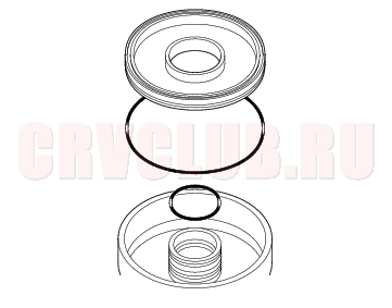
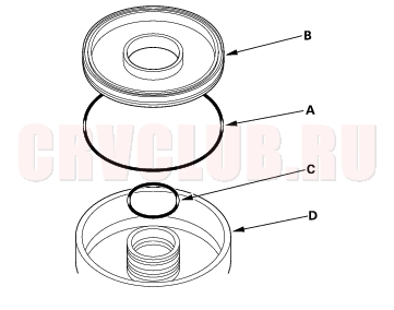
- Install the new O-rings (A) on the 3rd and 4th clutch piston (B).
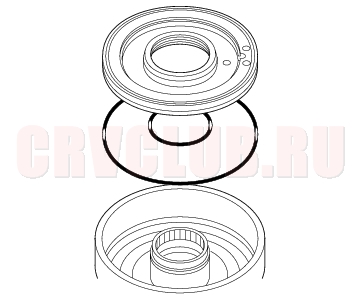
- Install the new O-ring (A) in the 1st, 2nd clutch pistons (B), and install the new O-ring (C) on the clutch drums (D).
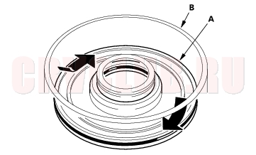
- Install the clutch piston (A) in the clutch drum (B). Apply pressure and rotate to ensure proper seating. Lubricate the piston O-ring with ATF before installing. Do not pinch the O-ring by installing the piston with to much force.
Clutch Reassembly (cont'd)14-248
- Install the return spring (A) and spring retainer (B), and position the snap ring (C) on the retainer.
- Install the special tools.
- Be sure the special tool (A) is adjusted to have full contact with the spring retainer (B) on the 3rd and 4th clutches.
- Set the special tool (A) on the spring retainer (B) of the 1st and 2nd clutches in such a way that the special tool works on the clutch return spring (C).
14-249
- If either end of the special tool is set over an area of the spring retainer which is unsupported by the return spring, the retainer may be damaged.
- Compress the return spring.
- Install the snap ring with snap ring pliers.
- Remove the special tools.
- Assemble the 1st clutch of K20A4 and K20A5 engine models: Install the waved spring (A) in the 1st clutch drum (B). Starting with the clutch waved-plate, alternately install the clutch plates (4) (C) and discs (4) (D), then install the clutch end plate (E) with the flat side toward the disc.
Clutch Reassembly (cont'd)14-250
- Assemble the 2nd clutch of K20A4 and K20A5 engine models: Install the waved spring (A) in the 2nd clutch drum (B). Install the clutch flat-plate (C), then starting with the clutch disc, alternately install the clutch discs (4) (D) and waved-plates (3) (E), then install the clutch end plate (F) with the flat side toward the disc.
- Assemble the 3rd clutch of K20A4 and K20A5 engine models: Install the waved spring (A) in the 3rd clutch drum (B). Starting with the clutch waved-plate, alternately install the clutch plates (3) (C) and discs (3) (D), then install the clutch end plate (E) with the flat side toward the disc.
- Assemble the 4th clutch of K20A4 and K20A5 engine models: Install the waved spring (A) in the 4th clutch drum (B). Starting with the clutch waved-plate, alternately install the clutch plates (3) (C) and discs (3) (D), then install the clutch end plate (E) with the flat side toward the disc.
- Assemble the 1st clutch of K24A1 engine model: Install the waved spring (A) in the 1st clutch drum (B). Starting with the clutch waved-pate, alternately install the clutch plates (5) (C) and discs (5) (D), then install the clutch end plate (E) with the flat side toward the disc.
14-251
- Assemble the 2nd clutch of K24A1 engine model: Install the waved spring (A) in the 2nd clutch drum (B). Install the clutch flat-plate (C), clutch disc (D), and clutch flat-plate (E). Starting with the clutch disc, alternately install the clutch discs (4) (F) and clutch waved-pates (3) (G), then install the clutch end plate (H) with the flat side toward the disc.
- Assemble the 3rd clutch of K24A1 engine model: Install the waved spring (A) in the 3rd clutch drum (B). Starting with the clutch waved-plate, alternately install the clutch plates (3) (C) and discs (3) (D), then install the clutch end plate (E) with the flat side toward the disc.
- Assemble the 4th clutch of K24A1 engine model: Install the waved spring (A) in the 4th clutch drum (B). Starting with the clutch waved-plate, alternately install the clutch plates (3) (C) and discs (3) (D), then install the clutch end plate (E) with the flat side toward the disc.
- Install the snap ring with a screwdriver.
- Check that the clutch piston moves by applying air pressure into fluid passage.
|
A/T
Shafts and Clutches14-218 |