Transmission Housing14-254
|
A/T
Transmission Housing14-254 |
Transmission Housing14-254
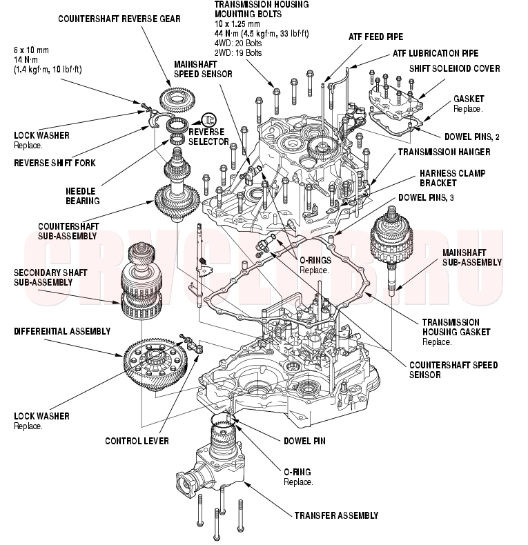
Shaft Assemblies and Housing Installation
Exploded View
14-255
Special Tools Required
Snap ring pliers 07LGC-0010100
NOTE: Refer to the Exploded View as needed during the following procedure. The Exploded View on previous page shows the 4WD transmission model; the 2WD transmission is similar.
- Install the differential assembly in the torque converter housing.
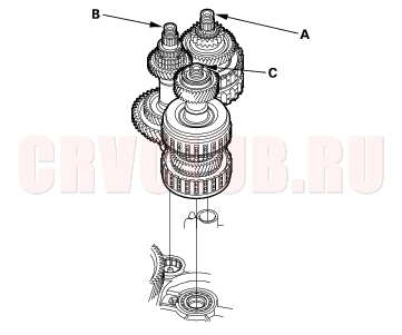
- Assemble the mainshaft, countershaft, and secondary shaft.
- Join the mainshaft sub-assembly (A), countershaft sub-assembly (B), and secondary shaft sub-assembly (C) together, and install them in the torque converter housing.
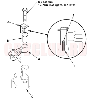
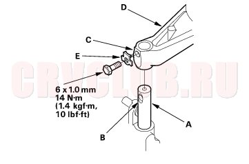
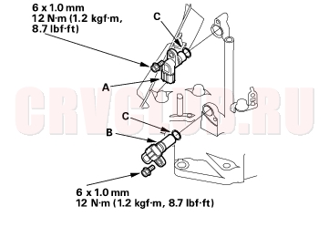
- If the detent arm was removed, install the detent arm (A) with arm collar (B) on the servo body (C), and install the new lock washer (D) with aligning its cutout (E) with the projection (F) of the servo body. Install and tighten the bolt, then bend the lock tab of the lock washer against the bolt head.
Shaft Assemblies and Housing Installation (cont'd)14-256
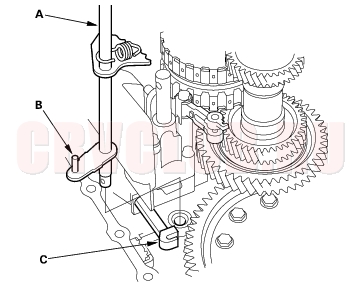
- Install the control shaft (A) in the torque converter housing aligning the manual valve lever pin (B) on the control shaft with the guide of the manual valve (C). Pull the manual valve gently when aligning the manual valve with the control shaft.
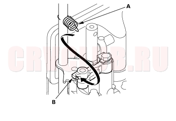
- Hook the detent arm spring (A) to the detent arm (B).
- Turn the shift fork shaft (A) so the large chamfered hole (B) is facing the fork bolt hole (C) of the shift fork (D).
- Install the shift fork and reverse selector together on the shift fork shaft and countershaft. Secure the shift fork to the shift fork shaft with the lock bolt and a new lock washer (E), then bend the lock tab of the lock washer against the bolt head.
- Install the needle bearing and countershaft reverse gear on the countershaft.
- Install the reverse idler gear in the transmission housing (see page 14-204) .
- Install the idler gear shaft (see page 14-233) , if it was removed.
- Install the three dowel pins and a new gasket on the torque converter housing.
14-257
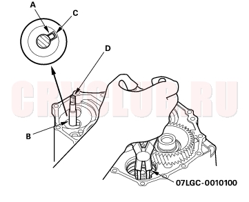
- Align the spring pin (A) on the control shaft (B) with the transmission housing groove (C) by turning the control shaft.
- NOTE: Do not squeeze the end (D) of the control shaft tips together when turning the shaft. If the tips are squeezed together will cause a faulty signal or position due to the play between the control shaft and the switch.
- Place the transmission housing on the torque converter housing. Do not install the mainshaft and countershaft speed sensors before installing the transmission housing on the torque converter housing.
- With expanding the snap ring of the secondary shaft bearing using the snap ring pliers, install the transmission housing as the bearing part-way into the housing. Then release the pliers, and push down the housing until it bottoms and until the snap ring snaps in place around the transmission housing snap ring groove.
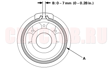
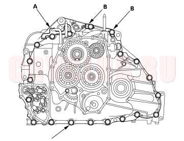
- Verify that the secondary shaft bearing snap ring (A) is seated in the bearing and housing groove, and that the ring end gap (B) is correct.
- Install the transmission housing mounting bolts along with the transmission hanger (A) and harness clamp brackets (B), tighten the bolts in two or three steps in a criss-cross pattern.
TRANSMISSION HOUSING MOUNTING BOLTS
10 x 1.25 mm
44 N·m (4.5 kgf·m, 33 lbf·ft)
4WD: 20 Bolts
2WD: 19 Bolts
Shaft Assemblies and Housing Installation (cont'd)14-258
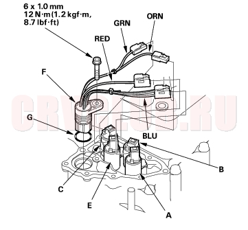
- Install the mainshaft speed sensor (A) and countershaft speed sensor (B) with new O-rings (C).
- Install the shift solenoid harness connector (F) in the transmission housing with the new O-ring (G).
- Connect the connector (BLU, WHT and WHT wires) to the shift solenoid valve A.
- Connect the connectors to respective solenoid valves:
- ORN wire to shift solenoid valve B.
- GRN wire to shift solenoid valve C.
- RED wire to shift solenoid valve E.
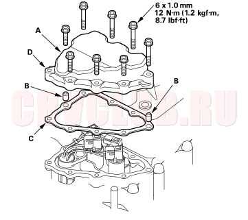
- Install the shift solenoid valve cover (A) with the two dowel pins (B) and the new gasket (C), and tighten the bolts (eight). Install the one bolt with the bracket for the ATF cooler line in the bolt hole (D) in step 34 in End Cover Installation (see step 34 on page 14-264 ).
|
A/T
Transmission Housing14-254 |