Transmission End Cover14-259
|
A/T
Transmission End Cover14-259 |
Transmission End Cover14-259
End Cover Installation
Special Tools Required
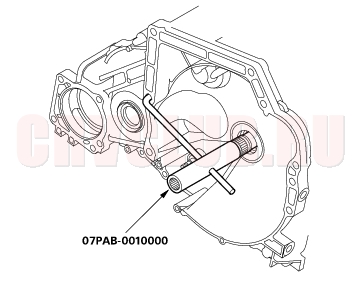
Mainshaft holder set 07PAB-0010000
- Install the special tool onto the mainshaft.
- Lubricate the following parts with ATF:
- Splines and threads of the mainshaft.
- Splines of the mainshaft idler gear.
- Old conical spring washer and old locknut.
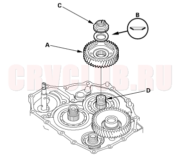
- Install the mainshaft idler gear (A), old conical spring washer (B), and old locknut (C) on the mainshaft (D), and tighten the locknut to 226 N·m (23.0 kgf·m, 166 lbf·ft).
- NOTE:
- Do not tap the idler gear to install.
- Use a torque wrench to tighten the locknut. Do not use an impact wrench.
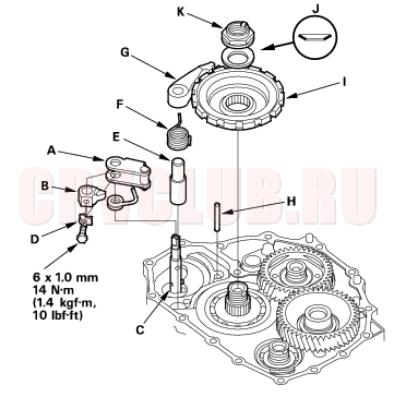
- Install the park lever (A) and park lever stop (B) on the control shaft (C), then install the lock bolt with the new lock washer (D). Do not bend the lock tab of the lock washer until step 18.
- Install the park pawl shaft (E), park pawl spring (F), park pawl (G), and stop shaft (H) on the transmission housing.
- Lubricate the following parts with ATF:
- Threads and splines of the countershaft.
- Old conical spring washer and old locknut.
- Areas where the park gear contacts the conical spring washer.
- Install the park gear (I), old conical spring washer (J), and old locknut (K) on the countershaft.
- Lift the park pawl up, and engage it with the park gear, then tighten the locknut to 226 N·m (23.0 kgf·m, 166 lbf·ft).
- NOTE:
- Do not tap the park gear to install.
- Use a torque wrench to tighten the locknut. Do not use an impact wrench.
- Countershaft locknut has left-hand threads.
- Remove the locknuts and conical spring washers from the mainshaft and countershaft.
End Cover Installation (cont'd)14-260
- Lubricate the threads of the shafts, the new locknuts and the new conical spring washers with ATF.
- Install the new conical spring washers (A) with facing stamped mark side up in the direction shown, and install the new mainshaft locknut (B), the new countershaft locknut (C), and the new secondary shaft locknut (D).
- Tighten the locknuts to 167 N·m (17.0 kgf·m, 123 lbf·ft).
- NOTE:
- Be sure to install the conical spring washers in the direction shown.
- Use a torque wrench to tighten the locknut. Do not use an impact wrench.
- Countershaft and secondary shaft locknuts have left-hand threads.
- Remove the special tool from the mainshaft.
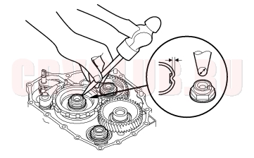
- Stake the locknuts into the shafts with a punch.
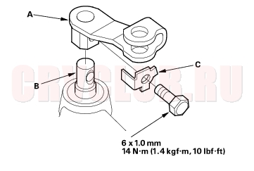
- Install the control level (A) on the control shaft (B), and install the bolt with the new lock washer (C), then bend the lock tab of the lock washer against the bolt head.
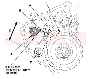
- Set the park lever in the [P] position, then verify that the park pawl (A) engages the park gear (B).
- If the park pawl does not engage fully, check the distance (C) between the pawl shaft (D) and the park lever roller pin (E) (see page 14-195) .
- Tighten the lock bolt, and bend the lock tab of the lock washer (F) against the bolt head.
14-261
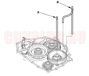
- Install the ATF feed pipe (A) into the idler gear shaft, and install the ATF lubrication pipe (B) into the transmission housing.
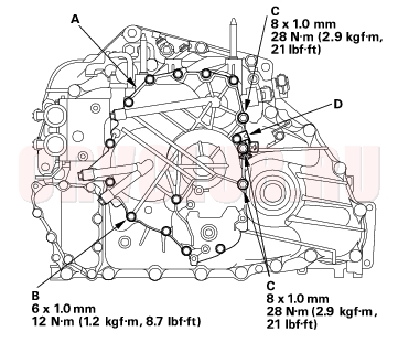
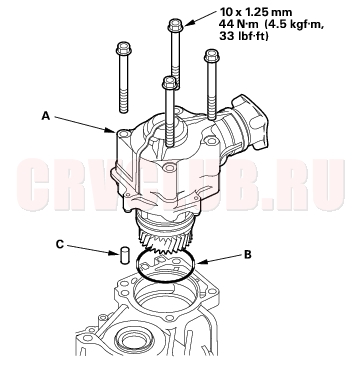
- Install the end cover (A) with the two dowel pins, new O-rings, and new gasket. Tighten the 6 x 1.0 mm bolts (12) (B) and 8 x 1.0 mm bolts (3) (C).
- Install the harness clamp bracket (D).
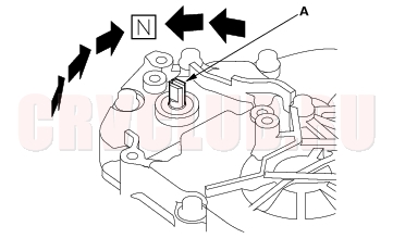
- Set the control shaft (A) to [N] position by turning the control lever on the torque converter side.
- NOTE: Do not squeeze the end of the control shaft tips together when turning the shaft. If the tips are squeezed together it will cause a faulty signal or position due to the play between the control shaft and the switch.
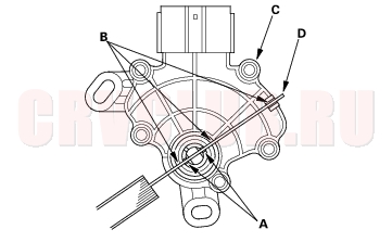
- Align the cutouts (A) on the rotary-frame with the neutral positioning cutouts (B) on the transmission range switch (C), then put a 2.0 mm (0.08 in.) feeler gauge blade (D) in the cutouts to hold in the [N] position.
- NOTE: Be sure to use a 2.0 mm (0.08 in.) blade or equivalent to hold the switch in the [N] position.
End Cover Installation (cont'd)14-262
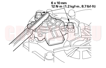
- Install the transmission range switch (A) gently on the control shaft (B) with holding the [N] position with the 2.0 mm (0.08 in.) blade (C).
- Tighten the bolts on the transmission range switch while you continue to hold the [N] position. Do not move the transmission range switch when tightening the bolts. Remove the feeler gauge.
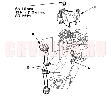
- Connect the transmission range switch connector (A) securely, then install the harness clamps (B) on the clamp bracket (C).
- Install the transmission range switch cover (D).
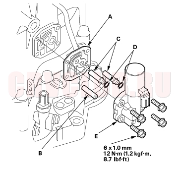
- Install the new gasket (A) on the transmission housing, and install the ATF pipe (B) and ATF joint pipes (C).
- Install the new O-rings (D) over the ATF joint pipes.
- Install the A/T clutch pressure control solenoid valve A (E).
14-263
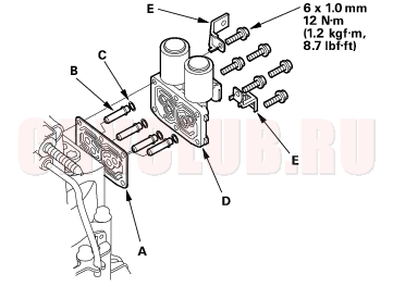
- Install the new gasket (A) on the transmission housing, and install the ATF joint pipes (B).
- Install the new O-rings (C) over the ATF joint pipes.
- Install the A/T clutch pressure control solenoid valves B and C (D), and harness clamp brackets (E).
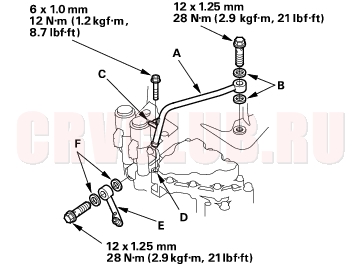
- Install the ATF cooler inlet line (A) with the new sealing washers (B), and install the bracket (C) of the ATF cooler inlet line on the shift solenoid valve cover hole (D) (described in step 22 (see page 14-258) in Shaft Assemblies and ATF Strainer Installation).
- Install the ATF cooler outlet line (E) with the new sealing washers (F).
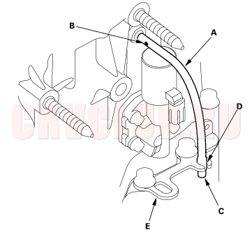
- Install the breather tube (A) with facing the dot (B) on the tube in a rearward position (differential side), then install the other end (C) in the slot (D) of the transmission hanger (E).
- For 4WD model: Install the transfer assembly (A) with the new O-ring (B) and dowel pin (C).
- Install the ATF dipstick.
|
A/T
Transmission End Cover14-259 |