Transmission End Cover14-192
|
A/T
Transmission End Cover14-192 |
Transmission End Cover14-192
End Cover Removal
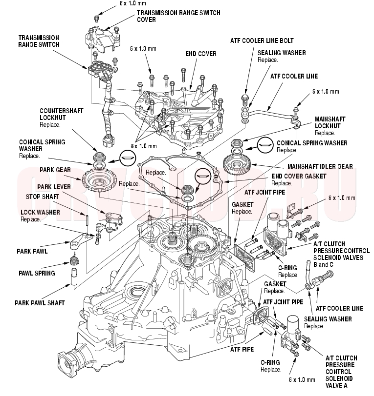
Exploded View -4WD
14-193
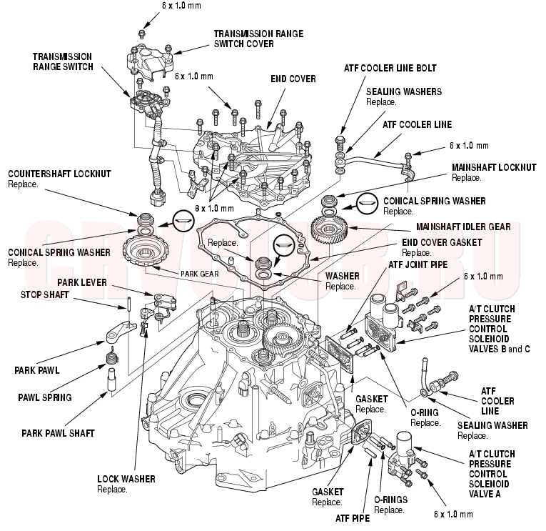
Exploded View -2WD
End Cover Removal (cont'd)14-194
Special Tools Required
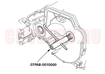
Mainshaft holder set 07PAB-0010000
NOTE: Refer to the Exploded View as needed during the following procedure.
- Remove the ATF cooler lines.
- Remove the A/T clutch pressure control solenoid valve A, then remove the ATF pipe, ATF joint pipes, and gasket.
- Remove the A/T clutch pressure control solenoid valves B and C, then remove the ATF joint pipes and gasket.
- Remove the transmission range switch cover.
- Remove the transmission range switch harness clamps from the clamp brackets, then remove the transmission range switch.
- Remove the end cover.
- Slip the special tool onto the mainshaft.
- Engage the park pawl with the park gear.
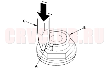
- Cut the lock tab (A) of the each shaft locknut (B) using a chisel (C). Then remove the locknuts and conical spring washers from each shaft.
- NOTE:
- Countershaft and secondary shaft locknuts have left-hand threads.
- Keep all of the chiseled particles out of the transmission.
- Clean the old mainshaft and countershaft locknuts; they are used to install the press fit idler gear on the mainshaft, and park gear on the countershaft.
- Remove the special tool from the mainshaft.
14-195
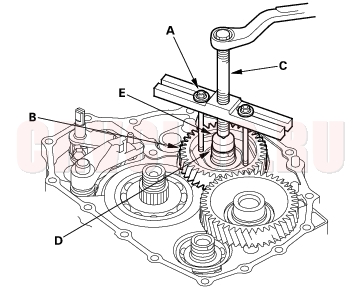
- Set a two-jaw (or three-jaw) puller (A) on the countershaft (B) with putting a collar (C) between the puller and countershaft, then remove the park gear (D).
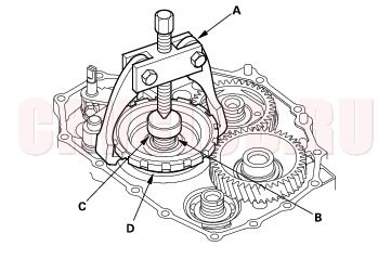
- Install 6 x 1.0 mm bolts (A) on the mainshaft idler gear (B). Set a puller (C) on the mainshaft (D) with putting a collar (E) between the puller and mainshaft, then remove the mainshaft idler gear.
- Remove the park pawl, park pawl spring, park pawl shaft, and stop shaft.
- Remove the park lever from the control shaft.
Park Lever Stop Inspection and Adjustment14-195
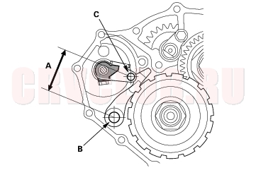
- Set the park lever in the [P] position.
- Measure the distance (A) between the park pawl shaft (B) and the park lever roller pin (C).
STANDARD: 57.7 - 58.7 mm (2.27 - 2.31 in.)
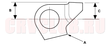
- If the measurement is out of standard, select and install the appropriate park lever stop (A) from the table below.
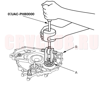
Idler Gear Shaft Bearing Replacement14-196
Special Tools Required
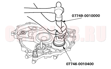
Adjustable bearing remover set 07JAC-PH80000 Handle driver 07749-0010000 Driver attachment, 52 x 55 mm 07746-0010400
- Remove the idler gear shaft bearing (A) from the end cover (B) with the special tool.
- Install the new bearing in the end cover with the special tools.
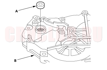
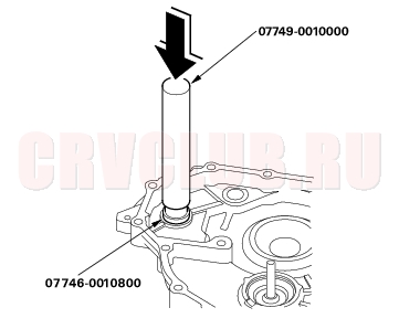
Control Shaft Oil Seal Replacement14-196
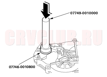
Special Tools Required
Handle driver 07749-0010000 Driver attachment, 22 x 24 mm 07746-0010800
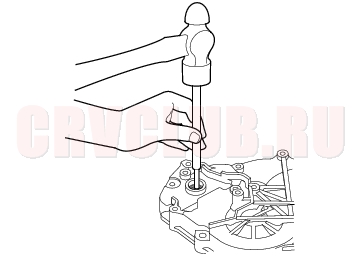
- Remove the oil seal (A) from the end cover (B).
- Install the new oil seal flush to the end cover with the special tools.
Control Shaft Bearing Replacement14-197
Special Tools Required
Handle driver 07749-0010000 Driver attachment, 22 x 24 mm 07746-0010800
- Remove the oil seal from the end cover, then remove the bearing.
- Install the new bearing flush to the end cover with the special tools.
- Install the new oil seal (see page 14-196) .
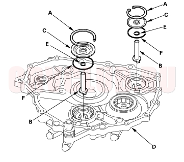
ATF Feed Pipes Replacement14-197
- Remove the snap rings (A), ATF feed pipes (B) and feed pipe flanges (C) from the end cover (D).
- Install the new O-ring (E) over the ATF feed pipe.
- Install the ATF feed pipe in the end cover with aligning the feed pipe tabs with the indentations in the end cover.
- Install the new O-ring (F) in the end cover, then install the feed pipe flange over the ATF feed pipe and O-ring.
- Secure the ATF feed pipe and feed pipe flange with the snap ring.
|
A/T
Transmission End Cover14-192 |