Automatic Transmission77-46
|
Supplement77-1
Automatic Transmission77-46 |
Automatic Transmission77-46
DTC with [D] Indicator Light Troubleshooting Procedures
How to Check for DTCs
Special Tool Required
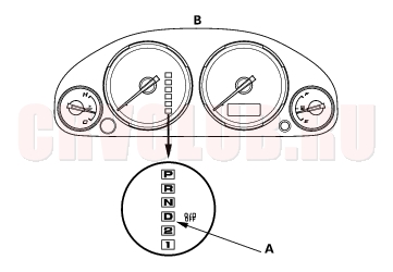
When the PCM senses an abnormality in the input or output systems, the [D] indicator (A) in the gauge assembly (B) will usually blink and/or the Malfunction Indicator Lamp (MIL) may come on. When the Data Link Connector (located under the dash behind the center console) is connected with the special tool (DLC Pin Box), and the SCS signal terminal is connected to ground with the jumper wire at the special tool. The [D] indicator will blink the Diagnostic Trouble Code (DTC) when the ignition switch is turned ON (II).
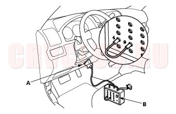
When the [D] indicator has been reported on, connect the DLC (A) with the special tool (DLC Pin Box), then connect the jumper wire between the terminals 4 and 9 at the special tool, and turn the switch (B) on. Turn the ignition switch ON (II), then observe the [D] indicator.
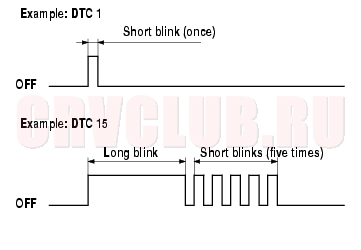
Codes 1 through 9 are indicated by individual short blinks. Code 10 and above are indicated by a series of long and short blinks. One long blink equals 10 short blinks. Add the long and short blinks together to determine the code. After determining the code, refer to the DTC Troubleshooting Index.
If the [D] indicator and the MIL come on at the same time, or if a driveability problem is suspected, follow this procedure:
- Record all fuel and emission DTCs, A/T DTCs.
- If there is fuel and emissions DTC, first check the fuel and emissions system as indicated by the DTC (except for DTC 70 on fuel and emission system, DTC 70 means there is one or more A/T DTCs, and no problems were detected in the fuel and emissions circuit of the PCM).
- Write down the radio station presets.
- Reset the memory by removing the No. 6 ECU fuse in the under-hood fuse/relay box for more than 10 seconds.
- Drive the vehicle for several minutes at speeds over 30 mph (50 km/h), and then recheck for DTC. If the A/T DTC returns, go to the DTC Troubleshooting Index. If the DTC does not return, there was an intermittent problem within the circuit. Make sure all pins and terminals in the circuit are tight, and then go to step 6.
- Reset the radio preset stations, and set the clock.
DTC Troubleshooting Index 77-47
by Number of [D] Indicator Blinking
5 Transmission range switch (short to ground) Blinks ON (see page 14-98) 6 Transmission range switch (open) OFF ON (see page 14-102) 7 Shift solenoid valve A Blinks ON (see page 14-79) 8 Shift solenoid valve B Blinks ON (see page 14-81) ) 9 Countershaft speed sensor Blinks ON (see page 14-71) 15 Mainshaft speed sensor Blinks ON (see page 14-68) ) 16 A/T clutch pressure control solenoid valve A Blinks ON (see page 14-76) 22 Shift solenoid valve C Blinks ON (see page 14-83) 23 A/T clutch pressure control solenoid valve B Blinks ON (see page 14-88) 25 2nd clutch pressure switch Blinks OFF (see page 14-94) 26 3rd clutch pressure switch Blinks OFF (see page 14-96) 28 ATF temperature sensor Blinks OFF (see page 14-66) 29 A/T clutch pressure control solenoid valve C Blinks ON (see page 14-92) 45 Mechanical problem in hydraulic control system Blinks ON (see page 14-90) 61 Shift solenoid valve E Blinks ON (see page 14-85) 62 Transmission range switch ([R] position circuit) Blinks OFF (see page 14-104) 70 Hydraulic control system of shift solenoid valve A circuit Blinks ON (see page 14-78) 76 Hydraulic control system of A/T clutch pressure control solenoid valve A circuit Blinks ON (see page 14-75) 77 Hydraulic control system of A/T clutch pressure control solenoid valve B circuit Blinks ON (see page 14-87) 78 Hydraulic control system of A/T clutch pressure control solenoid valve C circuit Blinks ON (see page 14-91)
|
Supplement77-1
Automatic Transmission77-46 |