Fuel and Emissions Systems77-2
|
Supplement77-1
Fuel and Emissions Systems77-2 |
Fuel and Emissions Systems77-2
Special Tools
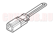
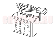
07PAZ-0010100 SCS Short Connector 1 07WAJ-0010100 DLC Pin Box 1
General Troubleshooting Information77-3
Intermittent Failures
The term ''intermittent failure'' means a system may have had a failure, but it checks OK now. If the Malfunction Indicator Lamp (MIL) on the dash does not come on, check for poor connections or loose wires at all connectors related to the circuit that you are troubleshooting.
Opens and Shorts
''Open'' and ''Short'' are common electrical terms. An open is a break in a wire or at a connection. A short is an accidental connection of a wire to ground or to another wire. In simple electronics, this usually means something won't work at all. In complex electronics (like ECM's/PCM's) this can sometimes mean something works, but not the way it's supposed to.
How to Troubleshooting
Special Tool Required
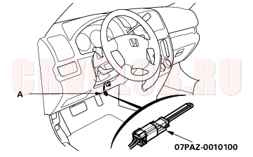
DLC pin box 07WAJ-0010100 SCS short connector 07PAZ-0010100 If the MIL (Malfunction Indicator Lamp) has come on
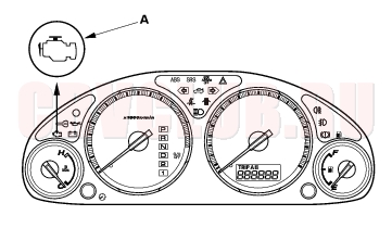
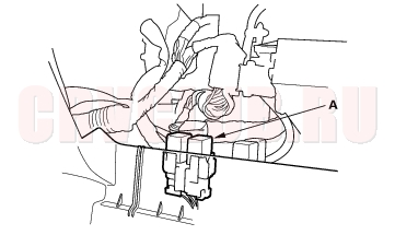
- Start the engine and check the MIL (A).
- Except KG, KS, KE, KR, KU (Hong Kong) models:
- If the MIL stays on, jump the SCS line
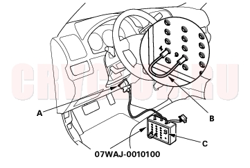
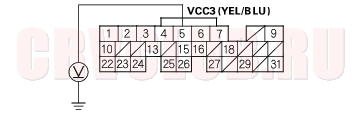
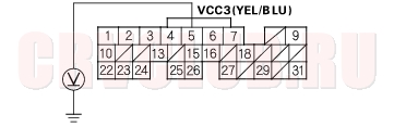
- Connect the DLC pin box to the 16P Data Link Connector (DLC) (A) located under the driver's side of the dashboard.
- Connect the DLC pin box terminals No. 4 and No. 9 with a jumper wire (B), then push the switch (C).
- KG, KS, KE, KR, KU (Hong Kong) models:
- If the MIL stays on, jump the SCS line
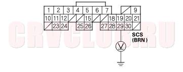
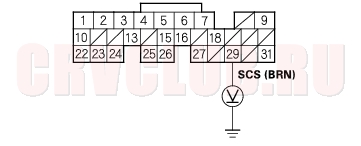
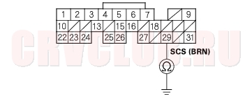
- With the ignition switch OFF, connect the SCS short connector to the service check connector (2P) (A) located under the dash on the driver's side of the dashboard.
General Troubleshooting Information (cont'd)77-4
Check the Diagnostic Trouble Code (DTC) and note it. Refer to the DTC Troubleshooting Index and begin the appropriate troubleshooting procedure. If the MIL did not come on
If the MIL did not come on but there is a driveability problem, refer to the Symptom Troubleshooting index in this section.
If you can't duplicate the DTC
Some of the troubleshooting in this section requires you to reset the Engine Control Module (ECM)/Powertrain Control Module (PCM) and try to duplicate the DTC. If the problem is intermittent and you can't duplicate the code, do not continue through the procedure. To do so will only result in confusion and, possibly, a needlessly replaced ECM/PCM.
DTC Troubleshooting Index77-5
0 MIL does not comes on or does not go off, no DTC stored O (see page 77-33) 1*4 Primary Heated Oxygen Sensor (Primary HO2S) (Sensor 1) O (see page 77-6) 3 Manifold Absolute Pressure (MAP) Sensor O (see page 77-7) 4 Crankshaft Position (CKP) Sensor O (see page 11-88) 6 Engine Coolant Temperature (ECT) Sensor O (see page 77-9) 7 Throttle Position (TP) Sensor O (see page 77-11) 8 Top Dead Center Position (TDC) Sensor O (see page 11-100) 10 Intake Air Temperature (IAT) Sensor O (see page 77-13) 11*8 Idle Mixture Adjuster (IMA) X (see page 77-15) 13 Barometric Pressure (BARO) Sensor O (see page 11-93) 14 Idle Air Control (IAC) Valve O (see page 11-140) 17*2 Vehicle Speed Sensor O (see page 11-90) 20*6 Electrical Load Detector (ELD) X (see page 77-17) 21*7 VTEC System O (see page 11-130) 22*3 VTEC System O (see page 11-133) 23 Knock Sensor O (see page 11-87) 34 Engine Control Module (ECM)/Powertrain Control Module (PCM) Power Source Circuit Unexpected Voltage O (see page 11-91) 39 Serial Communication Link Malfunction X Refer to the Multiplex Control System Troubleshooting (see page 22A-231) 41*4 Primary Heated Oxygen Sensor (Primary HO2S) (Sensor 1) Heater O (see page 11-74) 45*3 Fuel Supply System O (see page 77-19) 56 VTC Oil Control Solenoid Valve O (see page 77-21) 57 Camshaft Position (CMP) Sensor O (see page 77-24) 61*3 Primary Heated Oxygen Sensor (Primary HO2S) (Sensor 1) O (see page 11-73) 63*5 Secondary Heated Oxygen Sensor (Secondary HO2S) (Sensor 2) O (see page 77-27) 65*5 Secondary Heated Oxygen Sensor (Secondary HO2S) (Sensor 2) Heater O (see page 11-78) 67*3 Catalyst System O (see page 11-188) 70*1 Automatic Transaxle X Refer to the Automatic Transmission DTC Troubleshooting Index (see page 14-7) 71*3 No.1 Cylinder Misfire O (see page 77-28) 72*3 No.2 Cylinder Misfire O (see page 77-28) 73*3 No.3 Cylinder Misfire O (see page 77-28) 74*3 No.4 Cylinder Misfire O (see page 77-28) 71*3 Any combination of the No.1, No.2, No.3, No.4 Cylinder Misfire O (see page 11-81) 72 73 74 92*3 Evaporative Emission (EVAP) Canister Purge Valve O (see page 11-193)
*3: KG, KS, KE, KR, KU (Hong Kong) models
*5: KG, KS, KE, KR, KU, KZ, FO, FQ models
*6: KG, KS, KE, KR, KU, KZ, FO, KQ, KK, KM models
*7: except KG, KS, KE, KR, KU (Hong Kong) models
DTC Troubleshooting77-6
DTC 1: Primaly HO2S (Sensor 1) Circuit Malfunction
- Reset the ECM/PCM (see page 11-4) .
- Start the engine. Hold the engine at 3,000 rpm (min-1) with no load (in Park or neutral) until the radiator fan comes on, then let it idle for at least one minute before test-driving.
- Test-drive under following conditions.
- M/T in 4th gear, A/T in 2nd position
- accelerate using wide open throttle for at least 5 seconds, then decelerate for at least 5 seconds with the throttle completely closed.
Is the MIL on and does it indicate DTC 1?
Yes : Go to step 4.
No : Intermittent failure, system is OK at this time. Check for poor connections or loose wires at the primary HO2S (Sensor 1) and at the ECM/PCM.

- Inspect fuel pressure (see page 11-154) .
Is it normal?
Yes : Go to step 5.
No : Check for fuel supply system.
- Let it idle for at least 1 minute before test-driving.
- Open the throttle wide open, then quickly release it.
- Measure voltage between ECM/PCM connector terminals A6 and A24.
Is the voltage above 0.6 V at wide open throttle to 4,500 rpm (min-1) and below 0.4 V when the throttle is quickly released from 4,500 rpm (min-1)?
Yes : Substitute a known-good ECM/PCM and recheck (see page 11-5). If the symptom/indication goes away, replace the original ECM/PCM.
No : Go to step 8.
- Turn the ignition switch OFF.
- Disconnect the primary HO2S (Sensor 1) 4P connector.
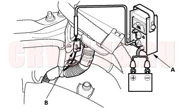
- At the primary HO2S (Sensor 1) harness side, connect the battery positive terminal to terminal No. 3 and battery negative terminal to terminal No. 4.
- Start the engine.
- After 2 minutes, measure voltage between primary HO2S (Sensor 1) 4P connector terminals No. 1 and No. 2.
Is the voltage above 0.6 V at wide open throttle to 4,500 rpm (min-1) and below 0.4 V when the throttle is quickly released from 4,500 rpm (min-1)?
Yes : Repair open or short in the wire between the ECM/PCM (A6) and the primary HO2S(Sensor 1).
No : Replace the primary HO2S (Sensor 1) (see page 11-119).
77-7
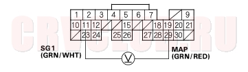
DTC 3: MAP Sensor Circuit Malfunction
- Reset the ECM/PCM (see page 11-4) .
- Start the engine and let it idle.
Is the MIL on and does it indicate DTC 3?
Yes : Go to step 3.
No : Intermittent failure, system is OK at this time. Check for poor connections or loose wires at the MAP sensor and at the ECM/PCM.
- Turn the ignition switch OFF.
- Turn the ignition switch ON (II).
- Measure voltage between ECM/PCM connector terminals A11 and A21.
Is there about 5 V?
Yes : Go to step 6.
No : Substitute a known-good ECM/PCM and recheck (see page 11-4) If the symptom/indication goes away, replace the original ECM/PCM.
Is there about 3 V?
Yes : Substitute a known-good ECM/PCM and recheck (see page 11-5). If the symptom/indication goes away, replace the original ECM/PCM.
No : Go to step 7.
Is there about 5 V?
Yes : Go to step 8.
No : Go to step 13.
- Turn the ignition switch OFF.
- Disconnect the MAP sensor 3P connector.
- Turn the ignition switch ON (II).
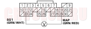
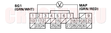
- Measure voltage between MAP sensor 3P connector terminals No. 1 and No. 3.
Is there about 5 V?
Yes : Go to step 12.
No : Repair open in the wire between the ECM/PCM (A11) and the MAP sensor.
DTC Troubleshooting (cont'd)77-8
Is there about 5 V?
Yes : Replace the MAP sensor.
No : Repair open in the wire between the ECM/PCM (A19) and the MAP sensor.
- Turn the ignition switch OFF.
- Disconnect the MAP sensor 3P connector.
- Turn the ignition switch ON (II).
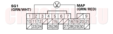
- Measure voltage between ECM/PCM connector terminals A11 and A19.
Is there about 5 V?
Yes : Replace the MAP sensor.
No : Go to step 17.
Is there about 5 V?
Yes : Go to step 18.
No : Repair open in the wire between the ECM/PCM (A21) and the MAP sensor.
- Turn the ignition switch OFF.
- Disconnect the negative cable from the battery.
- Disconnect ECM/PCM connector A (31P).
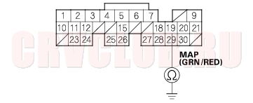
- Check for continuity between ECM/PCM connector terminal A19 and body ground.
Is there continuity?
Yes : Repair short in the wire between the ECM/PCM (A19) and the MAP sensor.
No : Substitute a known-good ECM/PCM and recheck (see page 11-5). If the symptom/indication goes away, replace the original ECM/PCM.
77-9
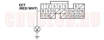
DTC 6: ECT Sensor Circuit Malfunction
- Reset the ECM/PCM (see page 11-4) .
- Turn the ignition switch ON (II).
Is the MIL on and does it indicate DTC 6?
Yes : Go to step 3.
No : Intermittent failure, system is OK at this time. Check for poor connections or loose wires at the ECT sensor, climate control unit (with climate control), and the ECM/PCM.
- Start the engine. Hold the engine at 3,000 rpm (min-1) with no load (in Park or neutral) until the radiator fan comes on, then let it idle.
- Turn the ignition switch OFF.
- Disconnect the ECT sensor 2P connector.
- Measure resistance between ECT sensor 2P connector terminals No. 1 and No. 2.
Is there 200 - 400
?
Yes : Go to step 7.
No : Replace the ECT sensor.
- Turn the ignition switch ON (II).
- At the engine wire harness side, measure voltage between ECT sensor 2P connector terminal No. 1 and body ground.
Is there about 5 V?
Yes : Go to step 9.
No : Go to step 10.
Is there about 5 V?
Yes : Substitute a known-good ECM/PCM and recheck (see page 11-5). If the symptom/indication goes away, replace the original ECM/PCM.
No : Repair open in the wire between the ECM/PCM (A10) and the ECT sensor.
DTC Troubleshooting (cont'd)77-10
- Turn the ignition switch OFF.
- Disconnect the climate control unit 30P connector.
- Turn the ignition switch ON(II).
- At the engine harness side, measure voltage between ECT sensor 2P connector terminal No. 2 and body ground.
Is there about 5 V?
Yes : Replace the climate control unit.
No : Go to step 14.
Is there about 5 V?
Yes : Repair open in the wire between the ECM/PCM (B8) and the ECT sensor.
No : Go to step 15.
- Turn the ignition switch OFF.
- Disconnecl the negative cable from the battery.
- Disconnect ECM/PCM connector B (24P).
- Check for continuity between ECM/PCM connector terminal B8 and body ground.
Is there continuity?
Yes : Repair short in the wire between the ECM/PCM (B8) and the ECT sensor.
No : Substitute a known-good ECM/PCM and recheck (see page 11-5). If the symptom/indication goes away, replace the original ECM/PCM.
77-11
DTC 7: TP Sensor Circuit Malfunction
- Reset the ECM/PCM (see page 11-4) .
- Start the engine.
Is the MIL on and does it indicate DTC 7?
Yes : Go to step 3.
No : Intermittent failure, system is OK at this time. Check for poor connections or loose wires at the TP sensor and at the ECM/PCM.
- Turn the ignition switch OFF.
- Turn the ignition switch ON (II).
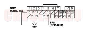
- Measure voltage between ECM/PCM connector terminals A10 and A15.
- NOTE: There should be a smooth transition as the throttle is pressed.
Is the voltage about 0.5 V at full close throttle, and about 4.5 V at full open throttle?
Yes : Substitute a known-good ECM/PCM and recheck (see page 11-5). If the symptom/indication goes away, replace the original ECM/PCM.
No : Go to step 6.
- Turn the ignition switch OFF.
- Disconnect the TP sensor 3P connector.
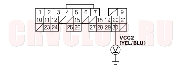
- Turn the ignition switch ON (II).
- At the engine wire harness side, measure voltage between TP sensor 3P connector terminal No. 1 and body ground.
Is there about 5 V?
Yes : Go to step 11.
No : Go to step 10.
Is there about 5 V?
Yes : Repair open in the wire between the ECM/PCM (A20) and the TP sensor.
No : Substitute a known-good ECM/PCM and recheck (see page 11-5). If the symptom/indication goes away, replace the original ECM/PCM.
DTC Troubleshooting (cont'd)77-12
- At the engine wire harness side, measure voltage between TP sensor 3P connector terminals No. 1 and No. 3.
Is there about 5 V?
Yes : Go to step 12.
No : Repair open in the wire between the ECM/PCM (A20) and the TP sensor.
- Turn the ignition switch OFF.
- Disconnect the negative cable from the battery.
- Disconnect ECM/PCM connector A (31P).
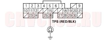
- Check for continuity between ECM/PCM connector terminal A15 and body ground.
Is there continuity?
Yes : Repair short in the wire between the ECM/PCM (A15) and the TP sensor.
No : Go to step 16.
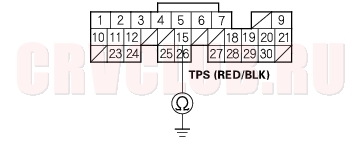
Is there continuity?
Yes : Replace the TP sensor.
No : Repair open in the wire between the ECM/PCM (A15) and the TP sensor.
77-13
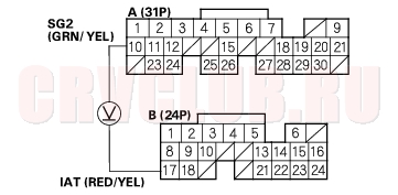
DTC 10: IAT Sensor Circuit Malfunction
- Reset the ECM/PCM (see page 11-4) .
- Turn the ignition switch ON (II).
Is the MIL on and does it indicate DTC 10?
Yes : Go to step 3.
No : Intermittent failure, system is OK at this time. Check for poor connections or loose wires at the IAT sensor and at the ECM/PCM.
- Turn the ignition switch OFF.
- Disconnect the IAT sensor 2P connector.
- Measure resistance between IAT sensor 2P connector terminals No. 1 and No. 2.
Is there 0.4 - 4.0 k
Yes : Go to step 6.
No : Replace the IAT sensor.
- Turn the ignition switch ON (II).
- At the engine wire harness side, measure voltage between IAT sensor 2P connector terminal No. 2 and body ground.
Is there about 5 V?
Yes : Go to step 8.
No : Go to step 9.
Is there about 5 V?
Yes : Substitute a known-good ECM/PCM and recheck (see page 11-5). If the symptom/indication goes away, replace the original ECM/PCM.
No : Repair open in the wire between the ECM/PCM (A10) and the IAT sensor.
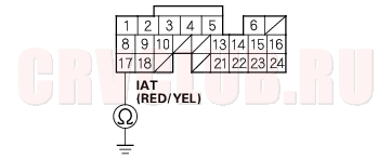
DTC Troubleshooting (cont'd)77-14
Is there about 5 V?
Yes : Repair open in the wire between the ECM/PCM (B17) and the IAT sensor.
No : Go to step 10.
- Turn the ignition switch OFF.
- Disconnect the negative cable from the battery.
- Disconnect ECM/PCM connector B (24P).
- Check for continuity between ECM/PCM connector terminal B17 and body ground.
Is there continuity?
Yes : Repair short in the wire between the ECM/PCM (B17) and the IAT sensor.
No : Substitute a known-good ECM/PCM and recheck (see page 11-5). If the symptom/indication goes away, replace the original ECM/PCM.
77-15
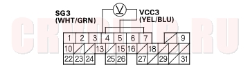
DTC 11: IMA Circuit Malfunction
- Reset the ECM/PCM (see page 11-4) .
- Start the engine, then let it idle for more than 5 seconds.
Is the MIL on and does it indicate DTC 11?
Yes : Go to step 3.
No : Intermittent failure, system is OK at this time. Check for poor connections or loose wires at the IMA sensor and at the ECM/PCM.
- Turn the ignition switch OFF.
- Turn the ignition switch ON (II).
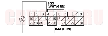
- Measure voltage between ECM/PCM connector terminals E4 and E5.
Is there about 5 V?
Yes : Go to step 6.
No : Substitute a known-good ECM/PCM and recheck (see page 11-5). If symptom/indication goes away, replace the original ECM/PCM.
Is there about 0.5 - 4.5 V?
Yes : Substitute a known-good ECM/PCM and recheck (see page 11-5). If symptom/indication goes away, replace the original ECM/PCM.
No : Go to step 7.
Is there about 5 V?
Yes : Go to step 8.
No : Go to step 13.
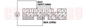
- Turn the ignition switch OFF.
- Disconnect the IMA 3P connector.
- Turn the ignition switch ON (II).
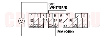
- Measure voltage between IMA 3P connector terminals No. 1 and No. 3.
Is there about 5 V?
Yes : Go to step 12.
No : Repair open in the wire between the ECM/PCM (E4) and the IMA.
DTC Troubleshooting (cont'd)77-16
Is there about 5 V?
Yes : Replace the IMA.
No : Repair open in the wire between the ECM/PCM (E15) and the IMA.
- Turn the ignition switch OFF.
- Disconnect the IMA 3P connector.
- Turn the ignition switch ON (II).
- Measure voltage between ECM/PCM connector terminals E4 and E15.
Is there about 5 V?
Yes : Replace the IMA.
No : Go to step 17.
Is there about 5 V?
Yes : Go to step 18.
No : Repair open in the wire between the ECM/PCM (E5) and the IMA.
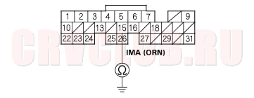
- Turn the ignition switch OFF.
- Disconnect the negative cable from the battery.
- Disconnect ECM/PCM connector E (31P).
- Check for continuity between ECM/PCM connector terminal E15 and body ground.
Is there continuity?
Yes : Repair short in the wire between the ECM/PCM (E15) and the IMA.
No : Substitute a known-good ECM/PCM and recheck (see page 11-5). If symptom/indication goes away, replace the original ECM/PCM.
77-17
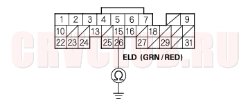
DTC 20: ELD Circuit Malfunction
- Reset the ECM/PCM (see page 11-4) .
- Start the engine and keep engine speed at idle.
- Turn the headlights on.
Does the MIL indicate DTC 20?
Yes : Go to step 4.
No : Intermittent failure, system is OK at this time. Check for poor connections or loose wires at the ELD and at the ECM/PCM.
- Turn the ignition switch OFF.
- Start the engine and let it idle.
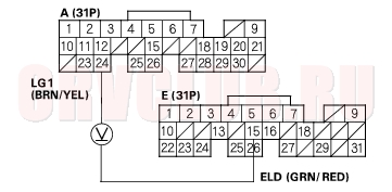
- Measure voltage between ECM/PCM connector terminals A24 and E15.
- While measuring voltage between ECM/PCM connector terminals A24 and E15, turn the headlights on (low).
Does the voltage drop when the headlights are turned on?
Yes : Substitute a known-good ECM/PCM and recheck (see page 11-5). If the symptom/indication goes away, replace the original ECM/PCM.
No : Go to step 8.
- Turn the ignition switch and headlights OFF.
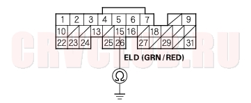
- Disconnect the ELD 3P connector.
- Turn the ignition switch ON (II).
- Measure voltage between ELD 3P connector terminals No. 1 and No. 2.
Is there battery voltage?
Yes : Go to step 12.
No : Go to step 19.
Is there about 5 V?
Yes : Replace the under-hood fuse/relay box.
No : Go to step 13.
DTC Troubleshooting (cont'd)77-18
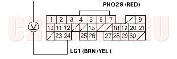
- Turn the ignition switch OFF
- Connect ELD 3P connector terminal No. 3 and body ground with a jumper wire.
- Disconnect ECM/PCM connector E (31P).
- Disconnect the negative cable from the battery.
- Check for continuity between body ground and ECM/PCM connector terminal E15.
Is there continuity?
Yes : Go to step 18.
No : Repair open in the wire between the ECM/PCM (E15) and the ELD.
Is there continuity?
Yes : Repair short in the wire between the ECM/PCM (E15) and the ELD.
No : Substitute a known-good ECM/PCM and recheck (see page 11-5). If symptom/indication goes away, replace the original ECM/PCM.
Is there battery voltage?
Yes : Repair open in the wire between the ELD and G201.
No : Check the No. 4 ACG (10A) fuse in the under-dash fuse/relay box. If the fuse is OK, repair open in the wire between No. 4 ACG (10A) fuse and the ELD.
77-19
DTC 45: Fuel System Malfunction
NOTE: If some of the DTCs listed below are stored at the same time as DTC 45, troubleshoot those DTCs first, then recheck for DTC 45.
DTC 3: MAP Sensor
DTC 41: Primary HO2S (Sensor 1) Heater
DTC 63: Secondary (Sensor 2) HO2S
DTC 65: Secondary HO2S (Sensor 2) Heater
DTC 22: VTEC System
DTC 56: VTC Oil Control Solenoid Valve
DTC 57: CMP Sensor
- Recheck the fuel pressure (see page 11-154) .
Is fuel pressure OK?
Yes : Go to step 2.
No : Check these items:
If the pressure is too high. Check the fuel pressure regulator. If the pressure is too low. Check the fuel pump, the fuel feed pipe, the fuel filter, and the fuel pressure regulator.
- Start the engine. Hold the engine at 3,000 rpm (min-1) with no load (in Park or neutral) until the radiator fan comes on.
- Measure voltage between ECM/PCM connector terminals A6 and A24.
Does it stay at less than 0.3 V or more than 0.6 V?
Yes : Replace the primary HO2S (Sensor 1).
No : Go to step 4.
Does it hold vacuum?
Yes : Go to step 5.
No : Replace the EVAP canister purge valve.
Is there about 3 V?
Yes : Go to step 6.
No : Replace the MAP sensor.
DTC Troubleshooting (cont'd)77-20
Is there 1.5 V or less within 1 second after starting the engine?
Yes : Check the valve clearance and adjust if necessary. If the valve clearances are OK, replace the injector.
No : Replace the MAP sensor.
77-21
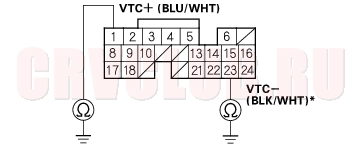
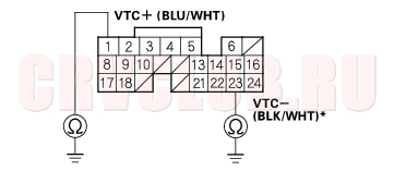
DTC 56: VTC Oil Control Solenoid Valve Malfunction
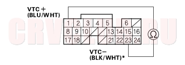
NOTE: Information marked with asterisk (*) applies to VTC- line
- Reset the ECM/PCM (see page 11-4) .
- Start the engine. Hold the engine at 3,000 rpm (min-1) with no load (in Park or neutral) until the radiator fan comes on, then let it idle.
Is DTC 56 indicated?
Yes : Go to step 6.
No : Go to step 3.
- Hold the engine at 3,000 rpm (min-1) with no load (in Park or neutral) until the radiator fan comes on.
- Test-drive at a steady speed between 30 - 60 km/h (20 - 40 mph) for 10 minutes.
- Jump the SCS line (see step 2 on page 77-3 ).
Is DTC 56 indicated?
Yes : Go to step 16.
No : Intermittent failure, system is OK at this time. Check for poor connections or loose wires at the VTC oil control solenoid valve and at the ECM/PCM.
- Turn the ignition switch OFF.
- Disconnect ECM/PCM connector B (24P).
- Disconnect the negative cable from the battery.
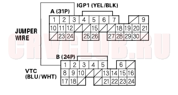
- Measure resistance between ECM/PCM connector terminal B1 and B23*.
Is there 6.75 - 8.25
Yes : Go to step 14.
No : Go to step 10.
- Disconnect the VTC oil control solenoid valve 2P connector.
- Measure resistance between VTC oil control solenoid valve 2P connector terminal No. 1* and No. 2.
Is there 6.75 - 8.25
Yes : Go to step 12.
No : Replace the VTC oil control solenoid valve.
DTC Troubleshooting (cont'd)77-22
- Connect VTC oil control solenoid valve 2P connector terminals No. 1, No. 2 and body ground with a jumper wire individually.
Is there continuity?
Yes : Go to step 14.
No : Repair open in the wire between the ECM/PCM (B1, B23*) and the VTC oil control solenoid valve.
Is there continuity?
Yes : Go to step 15.
No : Substitute a known-good ECM/PCM and recheck (see page 11-5). If the symptom/indication goes away with a known-good ECM/PCM, replace the original ECM/PCM.
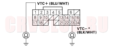
- Disconnect the VTC oil control solenoid valve 2P connector.
- Check for continuity between ECM/PCM connector terminal B1, B23* and body ground.
Is there continuity?
Yes : Repair short in the wire between the ECM/PCM (B1, B23*) and the VTC oil control solenoid valve.
No : Replace the VTC oil control solenoid valve.
77-23
Is the low oil pressure light on?
Yes : Check the oil pressure (see page 08-4).
No : Go to step 19.
- Check the VTC oil control solenoid valve (see page 11-137) .
Is the VTC oil control solenoid valve OK?
Yes : Go to step 20.
No : Clean the ports of the VTC oil control solenoid valve, or replace the VTC oil control solenoid valve.
- Install the VTC oil control solenoid valve.
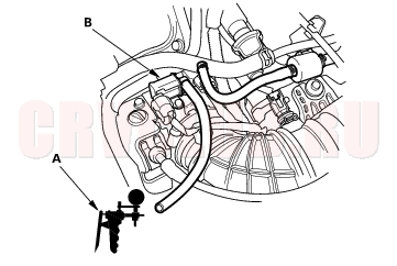
- Connect a tachometer (A) to the test tachometer connector (B).
- Start the engine. Hold the engine at 700 - 1,000 rpm (min-1).
- Connect the ECM/PCM connector terminal A3 and B1 with a jumper wire.
Did the engine stall or run rough?
Yes : Test-drive at a steady speed between 30 - 60 km/h (20 - 40 mph) for 10 minutes.
If temporary DTC P0011 is indicated, substitute a known-good ECM/PCM and recheck (see page 11-5). If the symptom/indication goes away with a known-good ECM/PCM, replace the original ECM/PCM.
No : Go to step 24.
DTC Troubleshooting (cont'd)77-24
- Check the VTC actuator (see page 06-8) .
Is the VTC actuator OK?
Yes : Remove the auto-tensioner (see page 04-31) and replace the VTC oil filter. Substitute a known-good ECM/PCM and recheck (see page 11-5). If the symptom/indication goes away with a known-good ECM/PCM, replace the original ECM/PCM.
No : Replace the VTC actuator.
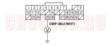
DTC 57: CMP Sensor Circuit Malfunction
- Reset the ECM/PCM (see page 11-4) .
- Start the engine.
Is the MIL on and does it indicated DTC 57?
Yes : Go to step 3.
No : Intermittent failure, system is OK at this time. Check for poor connections or loose wires at the CMP sensor and at the ECM/PCM.
- Turn the ignition switch OFF.
- Disconnect the CMP sensor 3P connector.
- Turn the ignition switch ON (II).
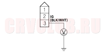
- Measure voltage between CMP sensor 3P connector terminal No. 3 and body ground.
Is there battery voltage?
Yes : Go to step 7.
No : Check the No. 4 ACG (10A) fuse in the under-dash fuse/relay box. If the fuse OK, repair open in the wire between the CMP sensor and No. 4 ACG (10A) fuse.
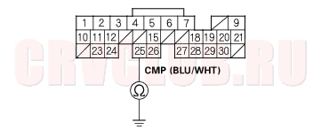
77-25
Is there about 5 V?
Yes : Go to step 8.
No : Go to step 10.
Is there battery voltage?
Yes : Go to step 9.
No : Repair open in the wire between the CMP sensor and G101.
Is the MIL on and does it indicated DTC 57?
Yes : Go to step 14.
No : Replace the original CMP sensor.
Is there about 5 V?
Yes : Repair open in the wire between the ECM/PCM (A25) and CMP sensor.
No : Go to step 11.
- Turn the ignition switch OFF.
- Disconnect the negative cable from the battery.
- Disconnect ECM/PCM connector A (31P).
- Check for continuity between ECM/PCM connector terminal A25 and body ground.
Is there continuity?
Yes : Repair short in the wire between the ECM/PCM (A25) and the CMP sensor.
No : Substitute a known-good ECM/PCM and recheck (see page 11-5). If the symptom/indication goes away with a known-good ECM/PCM, replace the original ECM/PCM.
DTC Troubleshooting (cont'd)77-26
- Check the VTC oil control solenoid valve (see page 11-137) .
Is the VTC oil control solenoid valve OK?
Yes : Go to step 16.
No : Clean the VTC oil control solenoid valve, or replace the VTC oil control solenoid valve.
- Remove the head cover and check the timing chain (see page 06-15) .
Is the timing chain OK?
Yes : Go to step 17.
No : Replace the timing chain.
- Check the slack in the cam chain (see page 06-22) .
Is the cam chain OK?
Yes : Go to step 18.
No : Replace the cam chain.
- Check the VTC actuator (see page 06-8) .
Is the VTC actuator OK?
Yes : Substitute a known-good ECM/PCM and recheck (see page 11-5). If the symptom/indication goes away with a known-good ECM/PCM, replace the original ECM/PCM.
No : Replace the VTC actuator.
77-27
DTC 63: Secondary HO2S (Sensor 2) Circuit Malfunction
- Reset the ECM/PCM (see page 11-4) .
- Jump the SCS line (see page 77-3) .
- Start the engine. Hold the engine at 3,000 rpm (min-1) with no load (in Park or neutral) until the radiator fan comes on, then let it idle for at least 1 minute before test-driving.
Is the MIL on and does it indicate DTC 63?
Yes : Go to step 4.
No : Intermittent failure, system is OK at this time. Check for poor connections or loose wires at the secondary HO2S (Sensor 2) and at the ECM/PCM.
- Inspect fuel pressure (see page 11-154) .
Is it normal?
Yes : Go to step 5.
No : Check for fuel supply system.
- Let it idle for at least 1 minute before test-driving.
- Open the throttle wide open, then quickly release it.
- Measure voltage between ECM/PCM connector terminals E2 and E4.
Is the voltage above 0.6 V at wide open throttle to 4,500 rpm (min-1) and below 0.4 V when the throttle is quickly released from 4,500 rpm (min-1)?
Yes : Substitute a known-good ECM/PCM and recheck (see page 11-5). If symptom/indication goes away, replace the original ECM/PCM.
No : Go to step 7.
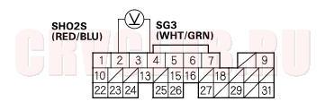
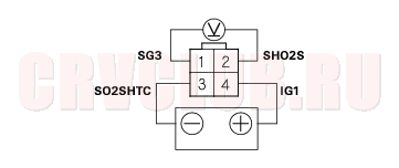
- Turn the ignition switch OFF.
- Disconnect the secondary HO2S (Sensor 2) 4P connector.
- At the secondary HO2S (Sensor 2) harness side, connect the battery positive terminal to terminal No. 4 and battery negative terminal to terminal No. 3.
- Start the engine.
- After 2 minute, measure voltage between secondary HO2S (Sensor 2) 4P connector terminals No. 1 and No. 2.
Is the voltage above 0.6 V at wide open throttle to 4,500 rpm (min-1) and below 0.4 V when the throttle is quickly released from 4,500 rpm (min-1)?
Yes : Repair open or short in the wire between the ECM/PCM (E2, E4) and the secondary HO2S (Sensor 2).
No : Replace the secondary HO2S (sensor 2).
DTC Troubleshooting (cont'd)77-28
DTC 71: No. 1 Cylinder Misfire
DTC 72: No. 2 Cylinder Misfire
DTC 73: No. 3 Cylinder Misfire
DTC 74: No. 4 Cylinder Misfire
NOTE: If some of the DTCs listed below are stored at the same time as a misfire DTC, troubleshoot those DTCs first, then recheck for the misfire DTC.
- Reset the ECM/PCM (see page 11-4) .
- Start the engine, and listen for a clicking sound at the injector at the problem cylinder.
Does it click?
Yes : Go to step 3.
No : Go to step 30.
- Turn the ignition switch OFF.
- Exchange the ignition coil from the problem cylinder with one from another cylinder.
- Start the engine. Hold the engine at 3,000 rpm (min-1) with no load (in Park or neutral) until the radiator fan comes on, then let it idle with the headlights, rear defogger, blower fan and air conditioner turned off.
- Jump the SCS line (see page 77-3) .
- Test-drive the vehicle several times under vavious conditions.
Is DTC 71, 72, 73 or 74 indicated?
Yes : Go to step 8.
No : Intermittent misfire due to poor contact at the ignition coil connector (no misfire at this time).
Does the misfire occur in the other cylinder whose ignition coil was exchanged?
Yes : Replace the faulty ignition coil (see page 04-21).
No : Go to step 9.
- Turn the ignition switch OFF.
- Exchange the spark plug from the problem cylinder with one from another cylinder.
- Test-drive the vehicle several times under vavious conditions.
Is DTC 71, 72, 73 or 74 indicated?
Yes : Go to step 12.
No : Intermittent misfire due to spark plug fouling, etc. (on misfire at that time).
Does the misfire occur in the other cylinder whose spark plug was exchanged?
Yes : Replace the faulty spark plug.
No : Go to step 13.
77-29
- Turn the ignition switch OFF.
- Exchange the injector from the problem cylinder with one from the another cylinder.
- Let the engine idle for 2 minutes.
- Test-drive the vehicle several times under various conditions.
Is DTC 71, 72, 73 or 74 indicated?
Yes : Go to step 17.
No : Intermittent misfire due to bad contact in the injector connector (no misfire at this time).
Does the misfire occur in the other cylinder whose injector was exchanged?
Yes : Replace the faulty injector.
No : Go to step 18.
- Turn the ignition switch OFF.
- Disconnect the ignition coil 3P connector from the problem cylinder.
- Turn the ignition switch ON (II).
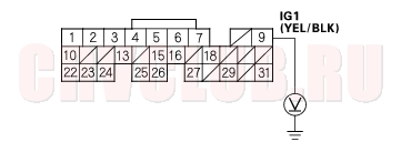
- Measure voltage between ignition coil 3P connector terminal No. 3 and body ground.
Is there battery voltage?
Yes : Go to step 22.
No : Repair open or short in the wire between the No. 1 IGN COIL (15A) fuse and the ignition coil.
- Turn the ignition switch OFF.
- Check for continuity between ignition coil 3P connector terminal No. 2 and body ground.
Is there continuity?
Yes : Go to step 24.
No : Repair open in the wire between the ignition coil and G101.
DTC Troubleshooting (cont'd)77-30
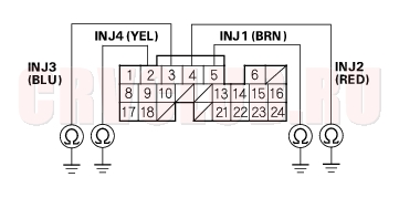
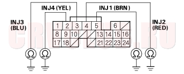
No. 1 DTC 71 A30 YEL/GRN No. 2 DTC 72 A29 BLU/RED No. 3 DTC 73 A28 WHT/BLU No. 4 DTC 74 A27 BRN
Is there continuity?
Yes : Repair short in the wire between the ECM/PCM and the ignition coil.
No : Go to step 27.
- Connect the ignition coil 3P connector terminal No. 1 and body ground with a jumper wire (see table).
No. 1 DTC 71 YEL/GRN No. 2 DTC 72 BLU/RED No. 3 DTC 73 WHT/BLU No. 4 DTC 74 BRN
No. 1 DTC 71 A30 YEL/GRN No. 2 DTC 72 A29 BLU/RED No. 3 DTC 73 A28 WHT/BLU No. 4 DTC 74 A27 BRN
Is there continuity?
Yes : Go to step 29.
No : Repair open in the wire between the ECM/PCM and the ignition coil.
Is the engine compression OK?
Yes : Substitute a known-good ECM/PCM and recheck (see page 11-5). If symptom/indication goes away, replace the original ECM/PCM.
No : Repair the engine.
- Disconnect the negative cable from the battery.
- Disconnect ECM/PCM connector B (24P).
- Reconnect the negative cable to the battery.
- Turn the ignition switch ON (II).
77-31
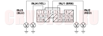
No. 1 DTC 71 B5 BRN No. 2 DTC 72 B4 RED No. 3 DTC 73 B3 BLU No. 4 DTC 74 B2 YEL
Is there battery voltage?
Yes : Go to step 35.
No : Go to step 43.
- Turn the ignition switch OFF, and remove the engine cover.
- Disconnect the injector 2P connector on the problem cylinder.
- Measure the resistance between the injector 2P connector terminals No. 1 and No. 2.
Is there 10
Yes : Go to step 38.
No : Replace the injector (see page 11-117).
- Exchange the injector from the problem cylinder with one from another cylinder.
- Jump the SCS line (see page 77-3) .
- Let the engine idle for 2 minutes.
- Test-drive the vehicle several times under various conditions.
Is DTC 71, 72, 73 or 74 indicated?
Yes : Go to step 42.
No : Intermittent misfire due to bad contact in the injector connector (no misfire at this time).
Does the misfire occur in the other cylinder whose injector was exchanged?
Yes : Replace the faulty injector.
No : Substitute a known-good ECM/PCM and recheck (see page 11-5). If symptom/indication goes away, replace the original ECM/PCM.
- Turn the ignition switch OFF.
- Remove the engine cover.
- Disconnect the injector 2P connector on the problem cylinder.
- Turn the ignition switch ON (II).
DTC Troubleshooting (cont'd)77-32
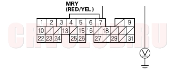
Is there battery voltage?
Yes : Go to step 48.
No : Repair open in the wire between the injector and the PGM-FI main relay.
- Turn the ignition switch OFF.
- Check for continuity between body ground and the appropriate ECM/PCM connector terminal (see table).
No. 1 DTC 71 B5 BRN No. 2 DTC 72 B4 RED No. 3 DTC 73 B3 BLU No. 4 DTC 74 B2 YEL
Is there continuity?
Yes : Repair short in the wire between the ECM/PCM and the injector.
No : Go to step 50.
- Connect the appropriate injector 2P connector terminal No. 2 to body ground with a jumper wire (see table).
No. 1 DTC 71 BRN No. 2 DTC 72 RED No. 3 DTC 73 BLU No. 4 DTC 74 YEL
- Check for continuity between body ground and the appropriate ECM/PCM connector terminal (see table).
No. 1 DTC 71 B5 BRN No. 2 DTC 72 B4 RED No. 3 DTC 73 B3 BLU No. 4 DTC 74 B2 YEL
Is there continuity?
Yes : Replace the injector, then recheck.
No : Repair open in the wire between the ECM/PCM and the injector.
MIL Circuit Troubleshooting77-33
Does the MIL come on and stay on?
Yes : If the MIL always come on and stays on, go to step 74. But if the MIL sometimes works normally, first check for these problems:
An intermittent short in the wire between the ECM/PCM (E29) and the Data Link Connector (DLC). An intermittent short in the wire between the ECM/PCM (E31) and the gauge assembly. No : If the MIL is always off, go to step 2. But if the MIL sometimes works normally, first check for these problems:
A loose No. 10 METER (7.5A) fuse in the under-dash fuse/relay box. A loose No. 20 IG (50A) fuse in the under-hood fuse/relay box. A loose No. 6 ECU (ECM/PCM) (15A) fuse in the under-hood fuse/relay box. A loose No. 17 FUEL PUMP (15A) fuse in the under-dash fuse/relay box. A poor connection at ECM/PCM terminal E31. An intermittent open in the GRN/WHT wire between the ECM/PCM (E31) and the gauge assembly. An intermittent short in the wire between the ECM/PCM (A21) and the manifold absolute pressure (MAP) sensor, countershaft speed sensor (A/T). An intermittent short in the wire between the ECM/PCM (A20) and the throttle position (TP) sensor, mainshaft speed sensor (A/T).
- KG, KS, KE, KR models:
- Turn the ignition switch OFF and press the inertia switch button.
- KG, KS, KE, KR models:
- Turn the ignition switch ON(II).
Does the MIL come on for 2 seconds after the ignition switch is turned ON (II)?
Yes : Intermittent failure system is OK at this time.
No : Go to step 4.
- KG, KS, KE, KR models:
- Turn the ignition switch OFF and disconnect the inertia switch 3P connector
- KG, KS, KE, KR models:
- Connect inertia switch 3P connector terminals No. 1 and No. 3 with a jumper wire.
Does the MIL come on for 2 seconds after the ignition switch is turned ON (II)?
Yes : Replace the inertia switch.
No : Go to step 7.
Is the low oil pressure light on?
Yes : Go to step 11.
No : Go to step 9.
Is the fuse OK?
Yes : Go to step 10.
No : Repair short in the wire between No. 10 METER (7.5A) fuse and the gauge assembly. Also replace the No. 10 METER (7.5A) fuse.
MIL Circuit Troubleshooting (cont'd)77-34
Is the fuse OK?
Yes : Repair open in the wire between the No. 20 IG (50A) fuse and the gauge assembly. If the wires are OK, test the ignition switch (see page 22A-63).
No : Repair short in the wire between the No. 20 IG (50A) fuse and the under-dash fuse/relay box. Also replace the No. 20 IG (50A) fuse.
Does the engine start?
Yes : Go to step 12.
No : Go to step 14.
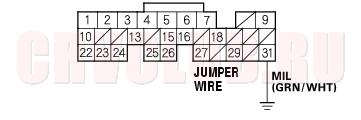
- Turn the ignition switch OFF. Connect ECM/PCM connector terminal E31 and body ground with a jumper wire.
Is the MIL on?
Yes : Substitute a known-good ECM/PCM and recheck (see page 11-5). If the symptom/indication goes away, replace the original ECM/PCM.
No : Check for an open in the wires between the ECM/PCM (E31) and the gauge assembly. Also check for a blown MIL bulb. If the wires and the bulb are OK, replace the gauge assembly.
- Turn the ignition switch OFF.
- Remove and inspect the No. 6 ECU (ECM/PCM) (15A) fuse in the under-hood fuse/relay box.
Is the fuse OK?
Yes : Go to step 21.
No : Go to step 16.
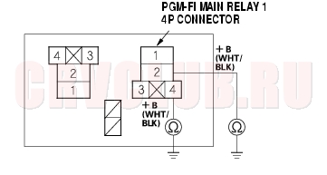
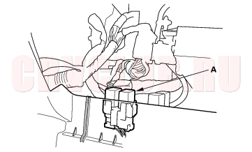
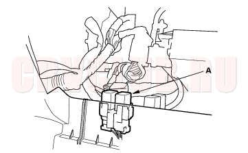
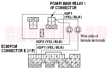
- Remove the glove box (see page 20-95) , PGM-FI main relay 1 (A).
*:The illustration shows LHD model.
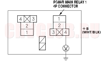
- Check for continuity between body ground and PGM-FI main relay 1 4P connector terminals No. 2 and No. 4 individually.
Is there continuity?
Yes : Repair short in the wire between the No. 6 ECU (ECM/PCM) (15A) fuse and the PGM-FI main relay 1. Also replace the No. 6 ECU (ECM/PCM) (15A) fuse.
No : Go to step 18.
77-35
- Disconnect each of the component or the connector sensors below, one at a time, and check for continuity between the PGM-FI main relay 1 4P connector terminal No. 1 and body ground.
- PGM-FI main relay 2
- ECM/PCM connector A (31P)
- Each injector 2P connector
- Idle air control (IAC) valve 3P connector
- Top dead center (TDC) sensor 2P connector
- Crankshaft position (CKP) sensor 3P connector
Is there continuity?
Yes : Go to step 19.
No : Replace the item that made continuity to body ground go away when disconnected. If the item is the ECM/PCM, substitute a known-good ECM/PCM and recheck (see page 11-5).
If the symptom/indication goes away, replace the original ECM/PCM.
Also replace the No. 6 ECU (ECM/PCM) (15A) fuse.
- Disconnected the connectors of all following items.
- PGM-FI main relay 2
- ECM/PCM connector A (31P)
- Injectors
- Idle air control (IAC) valve
- Top dead center (TDC) sensor
- Crankshaft position (CKP) sensor
- Check for continuity between PGM-FI main relay 1 4P connector terminals No. 1 and body ground.
Is there continuity?
Yes : Repair short in the wire between PGM-FI main relay 1 and each item. Also replace the No. 6 ECU (ECM/PCM) (15A) fuse.
No : Replace the PGM-FI main relay 1. Also replace the No. 6 ECU (ECM/PCM) (15A) fuse.
Is the fuse OK?
Yes : Go to step 32.
No : Go to step 22.
MIL Circuit Troubleshooting (cont'd)77-36
Is there continuity?
Yes : Go to step 25.
No : Replace the No. 17 FUEL PUMP (15A) fuse, and substitute a known-good ECM/PCM and recheck (see page 11-5). If the symptom/indication goes away, replace the original ECM/PCM.
- Remove the glove box (see page 20-95) , PGM-FI main relay 2 (A).
*: The illustration shows LHD model.
Is there continuity?
Yes : Repair short in the wire between the No. 17 FUEL PUMP (15A) fuse and the ECM/PCM (E9), or the No. 17 FUEL PUMP (15A) fuse and the PGM-FI main relay 2. Also replace the No. 17 FUEL PUMP (15A) fuse.
No : Go to step 27.
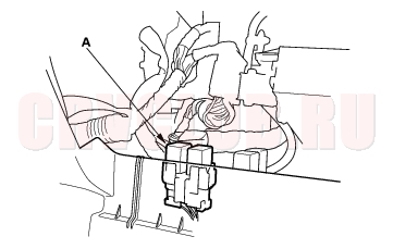
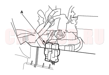
- Fold the rear seats forward, and pull back the carpet to expose the access panel.
- Remove the access panel from the floor. Disconnect the fuel pump 5P connector.
77-37
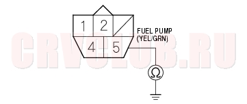
Is there continuity?
Yes : Repair short in the wire between the fuel pump and the PGM-FI main relay 2. Also replace the No. 17 FUEL PUMP (15A) fuse.
No : Go to step 30.
*: The illustration shows LHD model.
Is there continuity?
Yes : Replace PGM-FI main relay 2. Also replace the No. 17 FUEL PUMP (15A) fuse.
No : Check the fuel pump, and replace it as necessary. Also replace the No. 17 FUEL PUMP (15A) fuse.
- Disconnect the negative cable from the battery.
- Disconnect ECM/PCM connector E (31P).
- Reconnect the negative cable to the battery.
- Turn the ignition switch ON (II).
- Measure voltage between ECM/PCM connector terminals E9 and body ground.
Is there battery voltage?
Yes : Go to step 37.
No : Repair open in the wire between the No. 17 FUEL PUMP (15A) fuse and the ECM/PCM (E9).
MIL Circuit Troubleshooting (cont'd)77-38
Is there battery voltage?
Yes : Go to step 41.
No : Go to step 38.
*: The illustration shows LHD model.
Is there battery voltage?
Yes : Go to step 40.
No : Repair open in the wire between the No. 6 ECU (ECM/PCM) (15A) fuse and PGM-FI main relay 1.
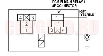
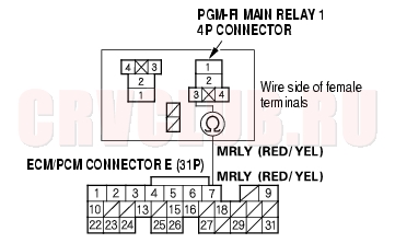
- Check for continuity between PGM-FI main relay 1 4P connector terminal No. 3 and ECM/PCM connector terminal E7.
Is there continuity?
Yes : Test PGM-FI main relay 1 (see page 22A-60). If the relay is OK, substitute a known-good ECM/PCM and recheck (see page 11-5). If the symptom/indication goes away, replace the original ECM/PCM.
No : Repair open in the wire between PGM-FI main relay 1 and the ECM/PCM (E7).
77-39
- Disconnect the negative cable from the battery.
- Reconnect ECM/PCM connector E (31P).
- Reconnect the negative cable to the battery.
- Turn the ignition switch ON (II).
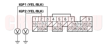
- Measure voltage between body ground and ECM/PCM connector terminals A2 and A3 individually.
Is there battery voltage?
Yes : Go to step 51.
No : Go to step 46.
*: The illustration shows LHD model.
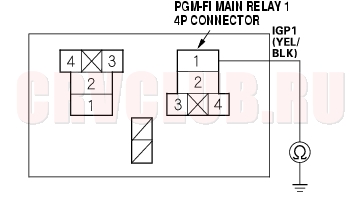
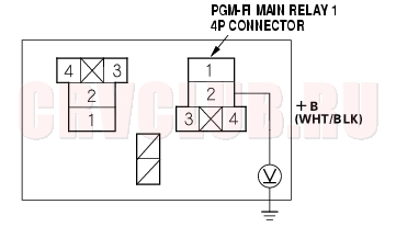
- Turn the ignition switch ON (II).
- Measure voltage between PGM-FI main relay 1 4P connector terminal No. 2 and body ground.
Is there battery voltage?
Yes : Go to step 49.
No : Repair open in the wire between the No. 6 ECU (ECM/PCM) (15A) fuse and PGM-FI main relay 1.
- Turn the ignition switch OFF.
- Check for continuity between PGM-FI main relay 1 4P connector terminal No. 1 and ECM/PCM connector terminals A2 and A3 individually.
Is there continuity?
Yes : Replace the PGM-FI main relay 1.
No : Repair open in the wire between PGM-FI main relay 1 and the ECM/PCM (A2, A3).
MIL Circuit Troubleshooting (cont'd)77-40
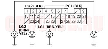
- Measure voltage between body ground and ECM/PCM connector terminals A4, A5, A23 and A24 individually.
Is there less than 1.0 V?
Yes : Repair open in the wire(s) that had more than 1.0 V between G101 and ECM/PCM (A4, A5, A23, A24).
No : Go to step 52.
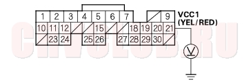
Is there about 5 V?
Yes : Go to step 59.
No : Go to step 53.
- Turn the ignition switch OFF.
- Disconnect the 3P connector from each of these sensors, one at a time, and measure voltage between body ground and ECM/PCM connector terminal A21 with the ignition switch ON (II).
- Manifold absolute pressure (MAP) sensor
- Countershaft speed sensor (A/T)
Is there about 5 V?
Yes : Replace the sensor that restored 5 V when disconnected.
No : Go to step 55.
- Turn the ignition switch OFF and disconnect the negative cable from the battery.
- Disconnect the 3P connector from the following sensors.
- Manifold absolute pressure (MAP) sensor
- Countershaft speed sensor (A/T)
- Disconnect ECM/PCM connector A (31P).
77-41
Is there continuity?
Yes : Repair short in the wire between ECM/PCM (A21) and the MAP sensor, countershaft speed sensor (A/T).
No : Substitute a known-good ECM/PCM and recheck (see page 11-5). If the symptom/indication goes away, replace the original ECM/PCM.
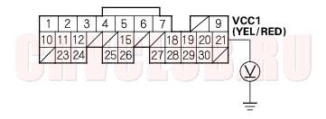
Is there about 5 V?
Yes : Go to step 66.
No : Go to step 60.
- Turn the ignition switch OFF.
- Disconnect the 3P connector from each of these sensors, one at a time, and measure voltage between body ground and ECM/PCM connector terminal A20 with the ignition switch ON (II).
- Throttle position (TP) sensor
- Mainshaft speed sensor (A/T)
Is there about 5 V?
Yes : Replace the sensor that restored about 5 V when disconnected.
No : Go to step 62.
- Turn the ignition switch OFF and disconnect the negative cable from the battery.
- Disconnect the 3P connector from the following sensors.
- Throttle position (TP) sensor
- Mainshaft speed sensor (A/T)
- Disconnect ECM/PCM connector A (31P).
MIL Circuit Troubleshooting (cont'd)77-42
Is there continuity?
Yes : Repair short in the wire between the ECM/PCM (A20) and the TP sensor, mainshaft speed sensor (A/T).
No : Substitute a known-good ECM/PCM and recheck (see page 11-5). If the symptom/indication goes away, replace the original ECM/PCM.
Is there about 5 V?
Yes : Substitute a known-good ECM/PCM and recheck (see page 11-5). If the symptom/indication goes away, replace the original ECM/PCM.
No : Go to step 67.
- Turn the ignition switch OFF.
- Disconnect the idle mixture adjuster (IMA) sensor 3P connector.
- Turn the ignition switch ON (II).
- Measure voltage between body ground and ECM/PCM connector terminal E5.
Is there about 5 V?
Yes : Replace the IMA.
No : Go to step 71.
- Turn the ignition switch OFF and disconnect the negative cable from the battery.
- Disconnect ECM/PCM connector E (31P).
- Check for continuity between ECM/PCM connector terminal E5 and body ground.
Is there continuity?
Yes : Repair short in the wire between ECM/PCM (E5) and the IMA.
No : Substitute a known-good ECM/PCM and recheck (see page 11-5). If the symptom/indication goes away, replace the original ECM/PCM.
77-43
- Turn the ignition switch OFF.
- Jump the SCS line (see step 2 on page 77-3 ).
- Turn the ignition switch ON (II), and read the MIL.
Does the OBD II scan tool/Honda PGM Tester communicate with the ECM/PCM?
Yes : Go to the DTC Troubleshooting index.
No : Go to step 77.
Is there about 5 V (or battery voltage)?
Yes : Repair open in the wire between the DLC and the ECM/PCM (E3, E29). After repairing it, check the DTC and go to the DTC Troubleshooting Index.
No : Go to step 79.
- Turn the ignition switch OFF.
- Disconnect the DLC Terminal Box or SCS short connector.
- Turn the ignition switch ON (II).
- Measure voltage between ECM/PCM connector terminal E29 and body ground.
Is there about 5 V (or battery voltage)?
Yes : Go to step 85.
No : Go to step 82.
- Turn the ignition switch OFF and disconnect the negative cable from the battery.
- Disconnect the ECM/PCM connector E (31P).
MIL Circuit Troubleshooting (cont'd)77-44
Is there continuity?
Yes : Repair short in the wire between the DLC and the ECM/PCM (E29).
No : Substitute a known-good ECM/PCM and recheck (see page 11-5). If the symptom/indication goes away, replace the original ECM/PCM.
- Turn the ignition switch OFF and disconnect the negative cable from the battery.
- Disconnect ECM/PCM connector E (31P).
- Reconnect the negative cable to the battery.
- Turn the ignition switch ON (II).
Is the MIL on?
Yes : Repair short in the wire between the gauge assembly and the ECM/PCM (E31). If the wires are OK, replace the gauge assembly.
No : Substitute a known-good ECM/PCM and recheck (see page 11-5). If the symptom/indication goes away, replace the original ECM/PCM.
Throttle Body Test77-45
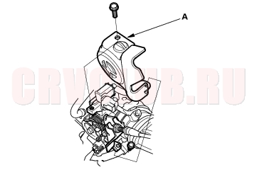
- Remove the throttle linkage cover (A).
- Check the throttle cable operation. The cable should operate without binding or sticking.
- If the cable is OK, go to step 3.
- If the cable binds or sticks, check the throttle cable and its routing. If it's faulty, reroute it or replace it and adjust it (see page 11-183) , then go to step 3.
- Operate the throttle lever by hand to see if the throttle valve and/or shaft are too loose or too tight.
- If there is excessive play in the throttle valve shaft or the throttle valve binds at the fully closed position, replace the throttle body.
- If the throttle valve and shaft are OK, go to step 4.
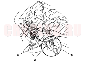
- Check for clearance (A) between the throttle stop screw (B) and the throttle lever (C) at the fully closed position. If there is any clearance, replace the throttle body (see page 11-185) . Do not adjust the throttle stop screw.
|
Supplement77-1
Fuel and Emissions Systems77-2 |