Automatic Transmission14-2
|
A/T
Automatic Transmission14-2 |
Automatic Transmission14-2
Service Precautions for 4WD Model
This 4WD model does not have the feature that mechanically switches between 4WD (four-wheel drive) and 2WD (front-wheel drive).
Do not drive the vehicle with rear wheels on the ground even though the front wheels are off the ground. The front wheel power is conveyed to the rear wheels, and the vehicle will start off.
Always lift the vehicle up so all four wheels are off the ground when testing and inspecting the vehicle to rotate the wheels such as Pressure Tests.
Use the free rollers under the rear wheels when performing test the vehicle with the speedometer tester.
Precautions on using free rollers:
Inspecting and testing using a chassis dynamometer is not feasible. Do not operate the accelerator, brake pedal or steering wheel abruptly. It may cause the vehicle to roll and create a hazardous condition. The maximum testing speed should be 50 km/h (31 mph). The maximum continuous operating time should be 3 minutes. Make sure to tie down the vehicle securely with the side anchor wires and center tie down wire. The free rollers are to be set under the rear wheels.
- Set the free rollers according to the wheel base and tread of the vehicle.
- Move the vehicle to position the front wheels on the speedometer tester and the rear wheels on the free rollers. Make sure to align the center of the wheels to the center of the speedometer tester and the free rollers.
- Tie down the vehicle securely using the towing hook and tie-down hook bracket to prevent the vehicle from rolling or over the free rollers.
- Start the engine, shift the transmission into the [D] position, accelerate the vehicle gradually, and measure the vehicle speed.
- After measurement, use the brake pedal to gradually decelerate and stop the vehicle.
Special Tools14-3
General Troubleshooting Information14-4
How to Check for DTCs with the PGM Tester/Scan Tool
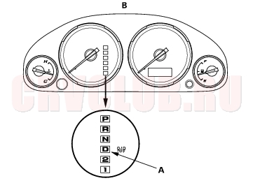
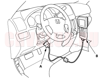
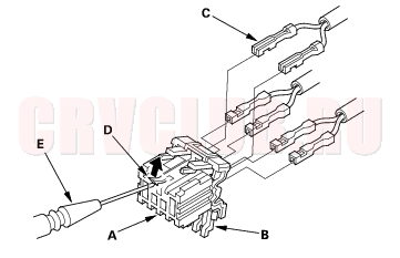
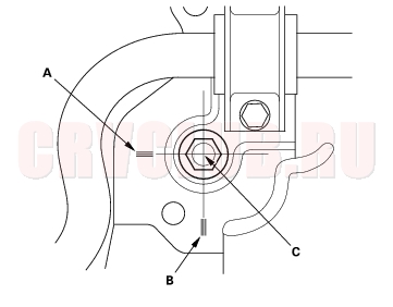
When the Powertrain Control Module (PCM) senses an abnormality in the input or output systems, the [D] indicator (A) in the gauge assembly (B) will usually blink.
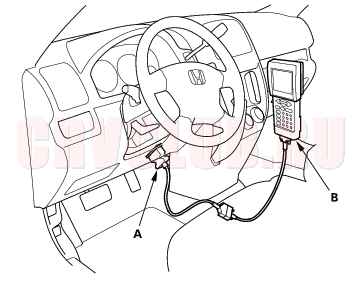
When the 16P Data Link Connector (DLC) (A) (located under the dash behind the center console) is connected to the OBD Scan Tool or Honda PGM Tester (B), it will indicate the Diagnostic Trouble Code (DTC) when the ignition switch is turned ON (II).
NOTE: The illustration shows LHD model; RHD is symmetrical.
If the [D] indicator or MIL has been reported on, or if a driveability problem is suspected, follow this procedure:
- Connect the OBD Scan Tool or Honda PGM Tester to the DLC. (See the OBD Scan Tool or Honda PGM Tester user's manual for specific instructions. If you are using the Honda PGM Tester, make sure it is set to the SAE DTC type).
- Turn the ignition switch ON (II), and observe the DTC on the screen.
- Record all fuel and emissions DTCs, A/T DTCs, and freeze data.
- If there is a fuel and emissions DTC, first check the fuel and emissions system as indicated by the DTC except for DTC P0700. DTC P0700 means there is one or more A/T DTCs, and no problems were detected in the fuel and emissions circuit of the PCM.
- Reset the DTC stored in the PCM with the OBD Scan Tool or PGM Tester.
- Drive the vehicle for several minutes under the same conditions as those indicated by the freeze data, or at speeds over 30 mph (50 km/h), and then recheck for DTC(s). If the A/T DTC returns, go to the DTC Troubleshooting Index. If the DTC does not return, there was an intermittent problem within the circuit. Make sure all pins and terminals in the circuit are tight.
- Reset the radio preset stations, and set the clock.
NOTE: You can also check for DTCs with SCS signal terminals short-circuited using with the special tool (DLC pin box 07WAJ-0010100) (see section Appendix).
14-5
How to Troubleshoot Circuits at the PCM
- Remove the glove box stops, then bring the glove box down.
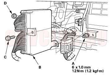
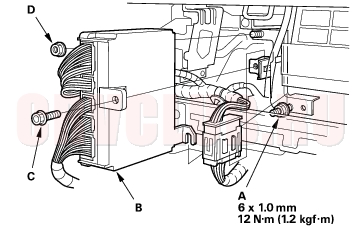
- Loosen the mounting nut (A) on the lower portion of the PCM (B), and remove the mounting bolt (C) and nut (D).
- NOTE: The illustration shows LHD model; RHD is symmetrical.
- Lift the PCM up to clear the mounting nut on the lower portion of the PCM, then pull out the PCM.
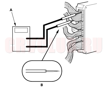
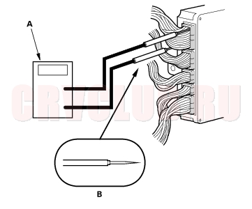
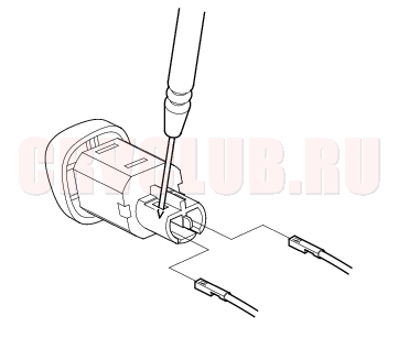
- Inspect the circuit on the PCM, according to the DTC troubleshooting with a digital multitester (A) and tapered tip probe (B) as shown.
- If you cannot get to the wire side of the connector or the wire side is sealed, disconnect the connector and use the tester probe to probe the connectors from the terminal side. Do not force the probe into the connector.
General Troubleshooting Information (cont'd)14-6
PCM Reset Procedure
- Write down the radio station presets.
- Turn the ignition switch OFF.
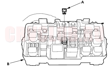
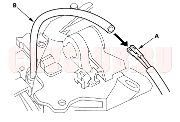
- Remove the No. 6 ECU fuse (15A) (A) from the under-hood fuse/relay box (B) for more than 10 seconds.
How to End a Troubleshooting Session
This procedure must be done after any troubleshooting.
- Turn the ignition switch OFF.
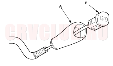
- Disconnect the Honda PGM tester (A) from the DLC (B).
- NOTE: The illustration shows LHD model; RHD is symmetrical.
- Reset the PCM.
- Turn the ignition switch ON (II).
- To verify that the problem is repaired, test-drive the vehicle for several minutes at speeds over 30 mph (50 km/h).
DTC Troubleshooting Index14-7
ATF temperature sensor (see page 14-66) Mainshaft speed sensor (see page 14-68) Countershaft speed sensor (see page 14-71) Hydraulic control system of A/T clutch pressure control solenoid valve A circuit (see page 14-75) A/T clutch pressure control solenoid valve A (see page 14-76) Hydraulic control system of shift solenoid valve A circuit (see page 14-78) Shift solenoid valve A (see page 14-79) Shift solenoid valve B (see page 14-81) Shift solenoid valve C (see page 14-83) Shift solenoid valve E (see page 14-85) Hydraulic control system of A/T clutch pressure control solenoid valve B circuit (see page 14-87) A/T clutch pressure control solenoid valve B (see page 14-88) Mechanical problem in hydraulic control system (see page 14-90) Hydraulic control system of A/T clutch pressure control solenoid valve C circuit (see page 14-91) A/T clutch pressure control solenoid valve C (see page 14-92) 2nd clutch pressure switch (see page 14-94) 3rd clutch pressure switch (see page 14-96) Transmission range switch (short to ground) (see page 14-98) Transmission range switch (open) (see page 14-102) Transmission range switch (short or open in [R] circuit) (see page 14-104)
Symptom Troubleshooting Index14-8
These symptom DO NOT trigger Diagnostic Trouble Codes (DTCs) or cause the [D] indicator to blink. If the Malfunction Indicator Lamp (MIL) was reported ON or the [D] indicator has been blinking, check for DTCs. But if the vehicle has one of the systems in the following chart, check the probable cause(s) for it, in the sequence listed, until you find the problem.
When you turn the ignition switch ON (II), the [D] indicator comes on and stays on or never comes on at all Communication line between multiplex control unit and gauge assembly defective Blown indicator bulb Check that the MIL indicates code for communication line between the multiplex control unit and gauge assembly (see page 22A- 231) . If the MIL does not indicate code, replace the indicator bulb (see page 14-171) . [D], [2], or [1] indicator does not indicate while the shift lever is in that position Over-drive (O/D) switch does not operate even though the switch is pushed in [D] position A problem in the O/D switch circuit Check the O/D switch circuit (see page 14-106) . Shift lever cannot be moved from [P] position while you're pushing on the brake pedal A problem in the shift lock system (interlock system) Check the interlock system - shift lock system circuit (see page 14- 175) . Shift lever cannot pass through [R] position from [N] position A problem in the reverse lock system of interlock system Check the interlock system - reverse lock system circuit (see page 14-178) . Ignition key cannot be moved from ACC (I) position to LOCK (0) position, when you're pushing it with the shift lever in [P] position A problem in the key interlock system (interlock system) Check the interlock system - key interlock system circuit (see page 14-179) .
14-9
Symptom Troubleshooting Index (cont'd)14-10
14-11
Symptom Troubleshooting Index (cont'd)14-12
14-13
Symptom Troubleshooting Index (cont'd)14-14
14-15
Syptom Troubleshooting Index (cont'd)14-16
14-17
Syptom Troubleshooting Index (cont'd)14-18
System Description14-19
General Operation
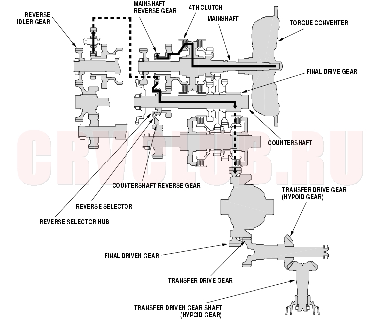
The automatic transmission is a combination of a 3-element torque converter and triple-shaft electronically controlled unit which provides 4 speeds forward and 1 reverse. The entire unit is positioned in line with the engine.
Torque Converter, Gears, and Clutches
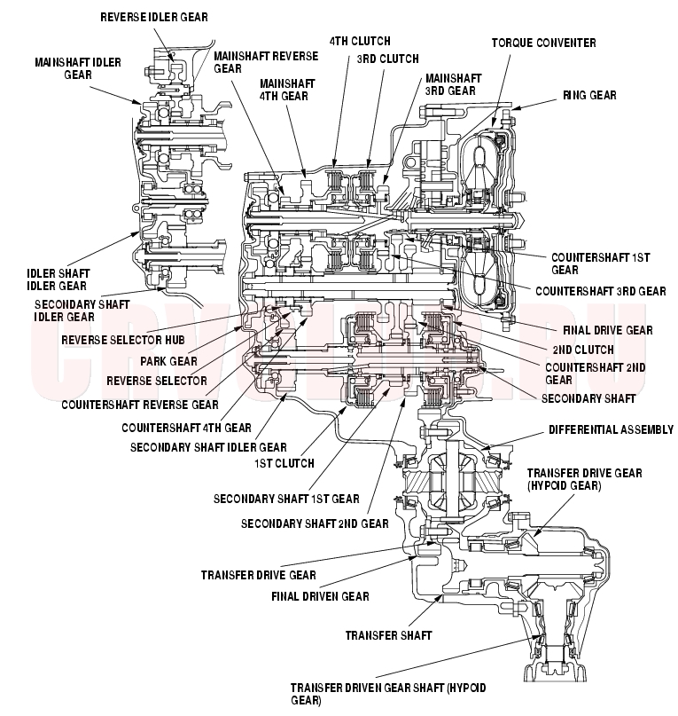
The torque converter consists of a pump, turbine, and stator assembly in a single unit. They are connected to the engine crankshaft so they turn together as the engine turns. Around the outside of the torque converter is a ring gear which meshes with the starter pinion when the engine is being started. The entire torque converter assembly serves as flywheel while transmitting power to the transmission mainshaft, the transmission has three parallel shafts; the mainshaft, the countershaft, the secondary shaft. The mainshaft is in line with the engine crankshaft, and includes the 3rd and 4th clutches, and gears for 3rd, 4th, reverse, and idler. The mainshaft reverse gear is integral with the mainshaft 4th gear. The countershaft includes the gears for 1st, 2nd, 3rd, 4th, reverse, park, and the final drive. The final drive gear is integral with the countershaft. The countershaft 4th gear and the countershaft reverse gear can be locked to the countershaft providing the 4th or reverse gear, depending on which way the selector is moved. The secondary shaft includes the 1st and 2nd clutches, and gears for 1st, 2nd, and idler. The idler shaft is located between the mainshaft and secondary shaft, and the idler gear transmits power between the mainshaft and the secondary shaft. The gears on the mainshaft and the secondary shaft are in constant mesh with those on the countershaft. When certain combinations of gears in the transmission are engaged by the clutches, power is transmitted from the mainshaft and the secondary shaft to the countershaft provide [D], [2], [1], and [R] positions.
Electronic Control
The electronic control system consists of the Powertrain Control Module (PCM), sensors, and solenoid valves. Shifting and lock-up are electronically controlled for comfortable driving under all conditions. The PCM is located below the dashboard, behind the glove box.
Hydraulic Control
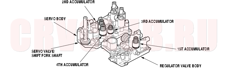
The valve bodies include the main valve body, the regulator valve body, and the servo body. They are bolted to the torque converter housing. The main valve body contains the manual valve, the shift valves A, B, C, and E, the relief valve, the lock-up control valve, the cooler check valve, the servo control valve, and the ATF pump gears. The regulator valve body contains the regulator valve, the torque converter check valve, lock-up shift valve, and the 1st accumulator. The servo body contains the servo valve, the CPB valve, accumulators for 2nd, 3rd and 4th and shift solenoid valves for A, B, C, and E. Fluid from the regulator passed through the manual valve to the various control valves. The 1st and 3rd clutches receive fluid their respective feed pipes, and the 2nd and the 4th clutches receive fluid from the internal hydraulic circuit.
Shift Control Mechanism
The PCM controls to shift gears the shift solenoid valves A, B, C, and E, and the A/T clutch pressure control solenoid valves A, B, and C, while receiving input signals from various sensors and switches located throughout the vehicle. The shift solenoid valves shift the positions of the shift valves to switch the port leading hydraulic pressure to the clutch. The A/T clutch pressure control solenoid valves A, B, and C regulate their respective pressure, and pressurize to the clutches to engage it and its corresponding gear. The pressures of the A/T clutch pressure control solenoid valves also apply to the shift valves to switch the port.
Lock-up Mechanism
The lock-up mechanism operates in [D] position (3rd and 4th) and [D] position over-drive off mode (3rd). The pressurized fluid is drained from the back of the torque converter through a fluid passage, causing the torque converter clutch piston to be held against the torque converter cover. As this takes place, the mainshaft rotates at the same speed as the engine crankshaft. Together with the hydraulic control, the PCM optimizes the timing and volume of the lock-up mechanism. When the shift solenoid valve E is turned on by the PCM, shift solenoid valve E pressure switch the lock-up shift valve lock-up on and off. The A/T clutch pressure control solenoid valve A and the lock-up control valve control the volume of the lock-up conditions.
System Description (cont'd)14-20
Gear Selection
The shift lever has six positions: [P] PARK, [R] REVERSE, [N] NEUTRAL, [D] DRIVE 1st through 4th gear range with Over-drive mode, and 1st through 3rd gear range with Over-drive OFF mode, [2] 2nd gear, and [1] 1st gear.
Starting is possible only in [P] and [N] positions because of a slide-type neutral-safety switch.
Automatic Transaxle (A/T) Gear Position Indicator
The A/T gear position indicator in the instrument panel shows which position has been selected.
Transfer Mechanism (4WD)
The transfer mechanism consists of the transfer drive gear on the differential, the transfer shaft, the transfer drive gear (hypoid gear), the transfer driven gear shaft (hypoid gear), and the companion flange. The transfer mechanism assembly is on the rear of the transmission, beside the differential. The transfer drive gear on the differential drives the transfer gear shaft and transfer driven gear (hypoid gear), and the transfer drive gear (hypoid gear) drives the transfer driven gear shaft (hypoid gear). Power is transmitted from the transfer drive gear on the differential to the rear differential via the transfer and the propeller shaft.
14-21
Transmission Cutaway View
NOTE: The illustration shows 4WD transmission on K20A4 and K20A5 engine models; 2WD does not have the transfer mechanism, K24A1 engine model is similar.
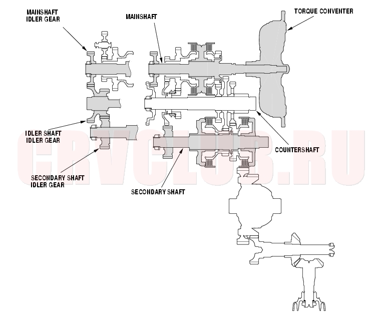
Idler Gears Section Cutway View
System Description (cont'd)14-22
Clutches
The 4-speed automatic transmission uses hydraulically-actuated clutches to engage or disengage the transmission gears. When hydraulic pressure is introduced into the clutch drum, the clutch piston moves. This presses the friction discs and steel plates together, locking them so they don't slip. Power is then transmitted through the engaged clutch pack to its hub-mounted gear. Likewise, when the hydraulic pressure is bled from the clutch pack, the piston releases the friction discs and steel plates, and they are free to slide past each other. This allows the gear to spin independently on its shaft, transmitting no power.
1st Clutch
The 1st clutch engages/disengages 1st gear, and is located at the middle of the secondary shaft. The 1st clutch is supplied hydraulic pressure by its ATF feed pipe within the secondary shaft.
2nd Clutch
The 2nd clutch engages/disengages 2nd gear, and is located at the end of the secondary shaft, opposite the end cover. The 2nd clutch is supplied hydraulic pressure by a circuit connected to the internal hydraulic circuit.
3rd Clutch
The 3rd clutch engages/disengages 3rd gear, and is located at the middle of the mainshaft. The 3rd clutch is joined back-to-back to the 4th clutch. The 3rd clutch is supplied hydraulic pressure by its ATF feed pipe within the mainshaft.
4th Clutch
The 4th clutch engasges/disengages 4th gear, as well as reverse gear, and is located at the middle of the mainshaft. The 4th clutch is joined back-to-back to the 3rd clutch. The 4th clutch is supplied hydraulic pressure by a circuit connected to the internal hydraulic circuit.
Gear operation
The 4th gear is engages/disengages with the mainshaft by the 4th clutch. The 3rd gear is engages/disengages with the mainshaft by the 3rd clutch. The reverse gear is engages/disengages with the mainshaft by the 4th clutch. The idler gear is splined with the mainshaft, and rotates with the mainshaft.
The final drive gear is integral with the countershaft. The 1st, 2nd, 3rd, and park gears are splined with the countershaft, and rotates with the countershaft. The 4th gear and reverse gear are rotate freely from the countershaft. The reverse selector engages 4th gear and reverse gear with the reverse selector hub. The reverse selector hub is splined to the countershaft so that the 4th gear and reverse gear engage with the countershaft.
The 1st gear is engaged/disengages with the secondary shaft by the 1st clutch. The 2nd gear is engaged/disengages with the secondary shaft by the 2nd clutch. The idler gear is splined with the secondary shaft, and rotates with the secondary shaft. The idler gear on the idler shaft transmits power between the mainshaft and the secondary shaft.
The reverse idler gear transmits power from the mainshaft reverse gear to the countershaft reverse gear, and changes rotation direction of the countershaft to reverse.
14-23
[P] Position
Hydraulic pressure is not applied to the clutches. Power is not transmitted to the countershaft. The countershaft is locked by the park pawl interlocking the park gear.
[N] Position
Engine power transmitted from the torque converter drives the mainshaft idler gear, the idler shaft idler gear, and the secondary shaft idler gear, but hydraulic pressure is not applied to the clutches. Power is not transmitted to the countershaft. In this position, the position of the reverse selector differs according to whether the shift lever shifted from [D] or [R] position:
When shifted from [D] position, the reverse selector engages with the countershaft 4th gear and the reverse selector hub, and the 4th gear engages with the countershaft. When shifted from [R] position, the reverse selector engages with the countershaft reverse gear and the reverse selector hub, and the reverse gear engages with the countershaft. NOTE: The illustration shows the 4WD transmission; 2WD does not have the transfer mechanism.
System Description (cont'd)14-24
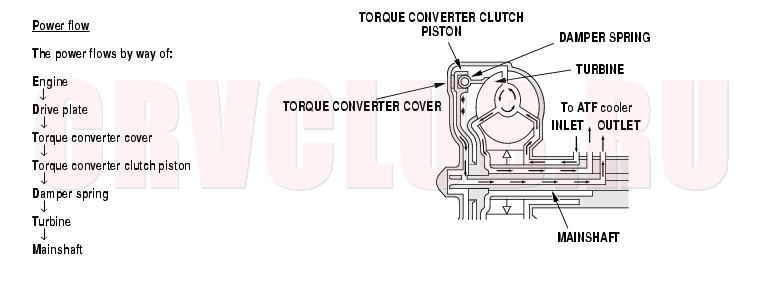
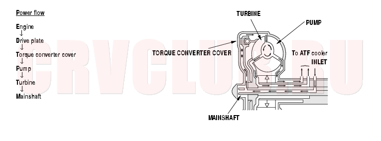
Power Flow
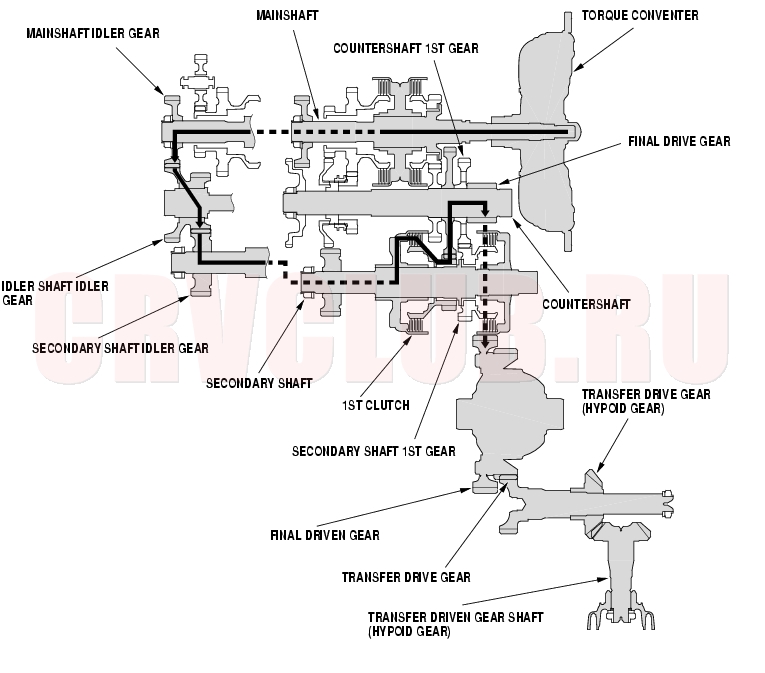
1st Gear
Hydraulic pressure is applied to the 1st clutch, then the 1st clutch engages the secondary shaft 1st gear with the secondary shaft. The mainshaft idler gear drives the secondary shaft via the idler shaft idler gear and the secondary shaft idler gear. The secondary shaft 1st gear drives the countershaft 1st gear and the countershaft. Power is transmitted to the final drive gear, which in turn drives the final driven gear and the transfer drive gear. The transfer drive gear drives the transfer drive gear (hypoid gear) and the transfer driven gear shaft (hypoid gear). NOTE: The illustration shows the 4WD transmission; 2WD does not have the transfer mechanism.
14-25
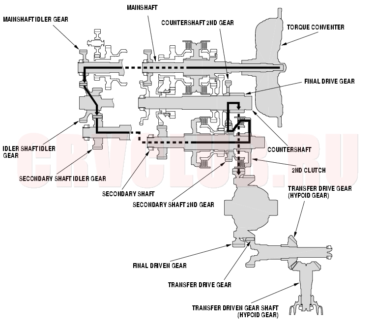
2nd Gear
Hydraulic pressure is applied to the 2nd clutch, then the 2nd clutch engages the secondary shaft 2nd gear with the secondary shaft. The mainshaft idler gear drives the secondary shaft via the idler shaft idler gear and the secondary shaft idler gear. The secondary shaft 2nd gear drives the countershaft 2nd gear and the countershaft. Power is transmitted to the final drive gear, which in turn drives the final driven gear and the transfer drive gear. The transfer drive gear drives the transfer drive gear (hypoid gear) and the transfer driven gear shaft (hypoid gear). NOTE: The illustration shows the 4WD transmission; 2WD does not have the transfer mechanism.
System Description (cont'd)14-26
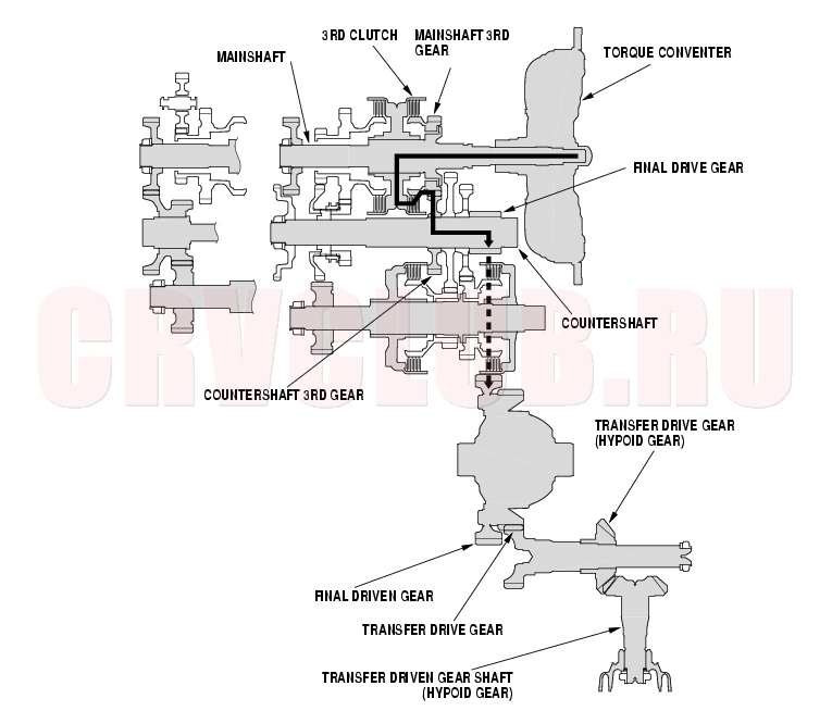
3rd Gear
Hydraulic pressure is applied to the 3rd clutch, then the 3rd clutch engages the mainshaft 3rd gear with the mainshaft. The mainshaft 3rd gear drives the countershaft 3rd gear and the countershaft. Power is transmitted to the final drive gear, which in turn drives the final driven gear and the transfer drive gear. The transfer drive gear drives the transfer drive gear (hypoid gear) and the transfer driven gear shaft (hypoid gear). NOTE: The illustration shows the 4WD transmission; 2WD does not have the transfer mechanism.
14-27
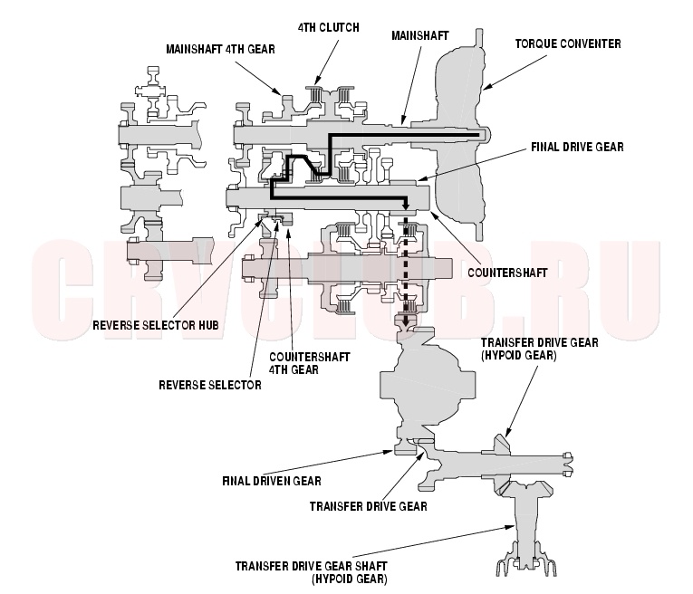
4th Gear
Hydraulic pressure is applied to the servo valve to engage the reverse selector with the countershaft 4th gear while the shift lever is in the [D], [2], [1] position (forward range). Hydraulic pressure is also applied to the 4th clutch, then the 4th clutch engages the mainshaft 4th gear with the mainshaft. The mainshaft 4th gear drives the countershaft 4th gear and the countershaft. Power is transmitted to the final drive gear, which in turn drives the final driven gear and the transfer drive gear. The transfer drive gear drives the transfer drive gear (hypoid gear) and the transfer driven gear shaft (hypoid gear). NOTE: The illustration shows the 4WD transmission; 2WD does not have the transfer mechanism.
System Description (cont'd)14-28
[R] Position
Hydraulic pressure is applied to the servo valve to engage the reverse selector with the countershaft reverse gear while the shift lever is in the [R] position. Hydraulic pressure is also applied to the 4th clutch, then the 4th clutch engages the mainshaft reverse gear with the mainshaft. The mainshaft reverse gear drives the countershaft reverse gear via the reverse idler gear. The rotation direction of the countershaft reverse gear is changed by the reverse idler gear. The countershaft reverse gear drives the countershaft via the reverse selector which drives the reverse selector hub. Power is transmitted to the final drive gear, which in turn drives the final driven gear and the transfer drive gear. The transfer drive gear drives the transfer drive gear (hypoid gear) and the transfer driven gear shaft (hypoid gear). NOTE: The illustration shows 4WD transmission; 2WD does not have the transfer mechanism.
14-29
Electronic Control System
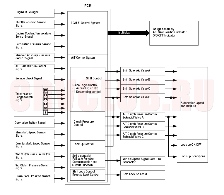
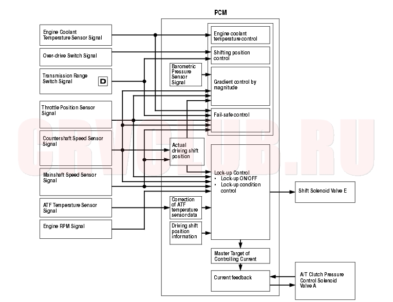
Functional Diagram
The electronic control system consists of the Powertrain Control Module (PCM), sensors, and solenoid valves.
Shifting and lock-up are electronically controlled for comfortable driving under all conditions.
The PCM inputs signals from the sensors, switches, and other control units, perform processing data, and outputs signals for engine control system and A/T control system. The A/T control system includes shift control, grade logic control, clutch pressure control, and lock-up control is stored in the PCM.
The PCM switches the shift solenoid valves and the A/T clutch pressure control solenoid valves on hydraulic control to control shifting transmission gears and lock-up torque converter clutch.
System Description (cont'd)14-30
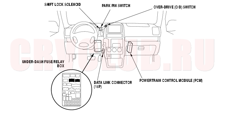
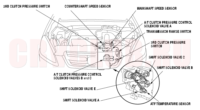
Electronic Controls Location
NOTE: The illustrations shows LHD model; RHD model is similar.
14-31
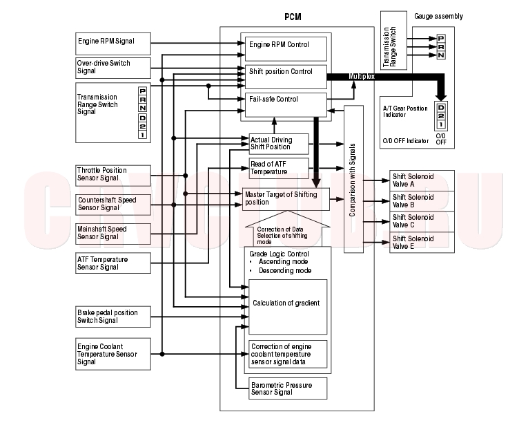
Shift Control
The PCM instantly determines which gear should be selected by various signals sent from sensors and switches, and it actuates the shift solenoid valves A, B, C, and E to control shifting.
Also, a Grade Logic Control System has been adopted to control shifting in [D] position. The PCM compares actual driving conditions with memorized driving conditions, based on the input from the throttle position sensor, the engine coolant temperature sensor, the barometric pressure sensor, the brake pedal position switch signal, and the shift lever position signal, to control shifting while vehicle is ascending or descending a slope.
System Description (cont'd)14-32
The PCM turns the shift solenoid valves A, B, C, and E ON and OFF to control shifting transmission gear. The combination of driving signals to shift solenoid valves A, B, C, and E are shown in table below.
14-33
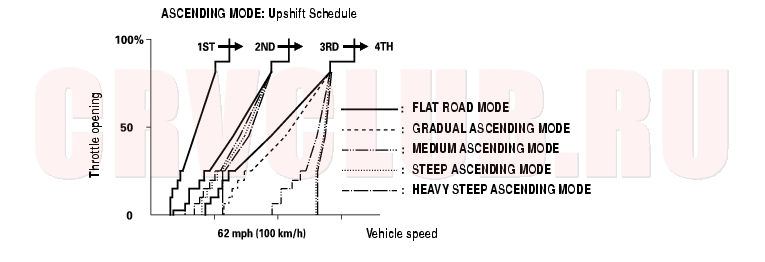
Grade Logic Control
When the PCM determines that the vehicle is climbing a hill in [D] position, the system extends the engagement area of 2nd, and 3rd gears to prevent the transmission from frequently shifting between 2nd and 3rd gears, and between 3rd and 4th gears, so the vehicle can run smooth and have more power when needed.
Shift schedules stored in the PCM between 2nd and 3rd gears, and between 3rd and 4th gears, enable it to automatically select the most suitable gear according to the magnitude of a gradient.
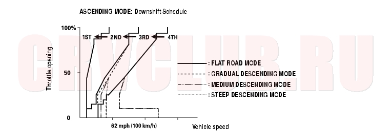
When the PCM determines that the vehicle is going down a hill in [D] position, the shift-up speed from 3rd to 4th gear, and from 2nd to 3rd gear (when the throttle is closed) becomes faster than the set speed for flat road driving to widen the 3rd gear and 2nd gear driving area. This, in combination with engine braking from the deceleration lock-up, achieves smooth driving when the vehicle is descending. There are three descending modes with different 3rd gear driving areas, and 2nd gear driving areas according to the magnitude of a gradient stored in the PCM. When the vehicle is 4th gear, and you are decelerating when you are applying the brakes on a steep hill, the transmission will downshift to lower gear. When you accelerate, the transmission will then return to higher gear.
System Description (cont'd)14-34
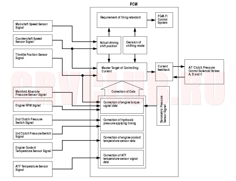
Clutch Pressure Control
The PCM actuates the A/T clutch pressure control solenoid valves A, B and C to control the clutch pressure. When shifting between lower and higher gears, the clutch pressure regulated by the A/T clutch pressure control solenoid valves A, B, and C engage and disengage the clutch smoothly.
The PCM inputs signals from the various sensors and switches, perform processing data, and outputs a current to the A/T clutch pressure control solenoid valves A, B, and C.
14-35
Lock-up Control
The shift solenoid valve E controls the hydraulic pressure to switch the lock-up shift valve and lock-up ON and OFF.
The PCM actuates the shift solenoid valve E and the A/T clutch pressure control solenoid valve A to control the torque converter clutch lock-up. When the shift solenoid valve E is turned ON, the condition of the lock-up starts.
The A/T clutch pressure control solenoid valve A regulates and apply the hydraulic pressure to the lock-up control valve to control the volume of the lock-up.
The lock-up mechanism operates in 3rd and 4th gears in [D] position, and 3rd gear in [D] position over-drive off mode.
System Description (cont'd)14-36
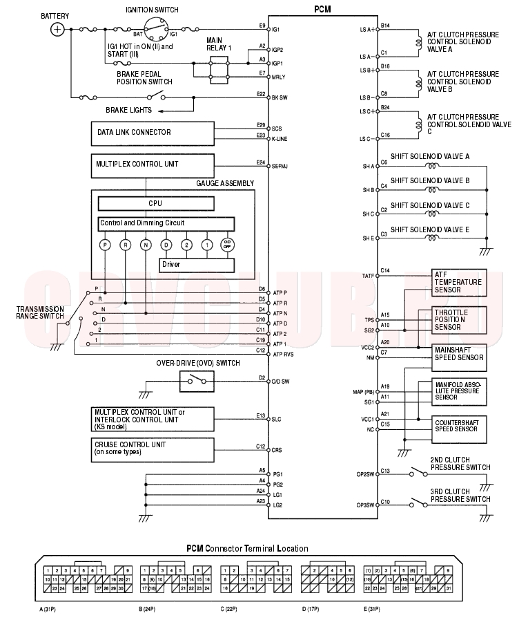
PCM Electrical Connections
14-37
PCM Inputs and Outputs
The PCM terminal voltage and measuring conditions are shown for the connector terminals that are related to the A/T control system. The other PCM terminal voltage and measuring conditions are described in section 11 (see section 11) .
System Description (cont'd)14-38
PCM Inputs and Outputs (cont'd)
14-39
System Description (cont'd)14-40
PCM Inputs and Outputs (cont'd)
14-41
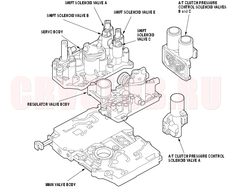
Hydraulic Controls
The valve body includes the main valve body, the regulator valve body, and the servo body. The ATF pump is driven by splines on the left end of the torque converter which is attached to the engine. Fluid flows through the regulator valve to maintain specified pressure through the main valve body to the manual valve, directing pressure to the shift valves and to each of the clutches via the solenoid valves. The shift solenoid valves A, B, C, and E are bolted on the servo body. The A/T clutch pressure control solenoid valves A, B, and C are mounted on the outside of the transmission housing.
System Description (cont'd)14-42
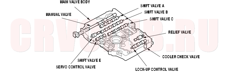
Main Valve Body
The main valve body contains the manual valve, the shift valves A, B, C, and E, the relief valve, the lock-up control valve, the cooler check valve, the servo control valve, and the ATF pump gears. The primary function of the main valve body is to switch fluid pressure on and off and to control hydraulic pressure going to the hydraulic control system.
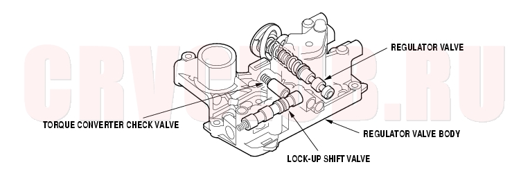
Regulator Valve Body
The regulator valve body contains the regulator valve, the torque converter check valve, lock-up shift valve, and the 1st accumulator.
14-43
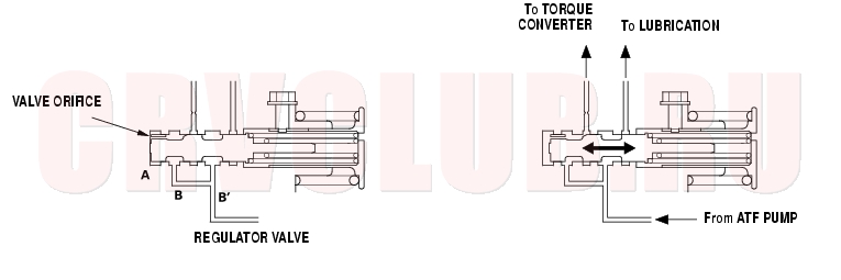
Regulator Valve
The regulator valve maintains a constant hydraulic pressure from the ATF pump to the hydraulic control system, while also furnishing fluid to the lubrication system and torque converter. The fluid from the ATF pump flows through B and B'. Fluid entering from B flows through the valve orifice to the A cavity. This pressure of the A cavity pushes the regulator valve to the right side, and this movement of the regulator valve uncovers the fluid port to the torque converter and the relief valve. The fluid flows out to the torque converter and the relief valve, and the regulator valve moves to the left side. According to the level of the hydraulic pressure through B, the position of the regulator valve changes, and the amount of fluid from B' through torque converter also changes. This operation is continued, maintaining the line pressure.
NOTE: When used, ''left'' or ''right'' indicates direction on the illustration below.
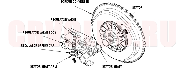
Increases in hydraulic pressure according to torque are performed by the regulator valve using stator torque reaction. The stator shaft is splined with the stator in the torque converter, and its arm end contacts the regulator spring cap. When the vehicle is accelerating or climbing (Torque Converter Range), stator torque reaction acts on the stator shaft, and the stator arm pushes the regulator spring cap in the direction of the arrow in proportion to the reaction. The stator reaction spring compresses, and the regulator valve moves to increase the line pressure which is regulated by the regulator valve. The line pressure reaches its maximum when the stator torque reaction reaches its maximum.
System Description (cont'd)14-44
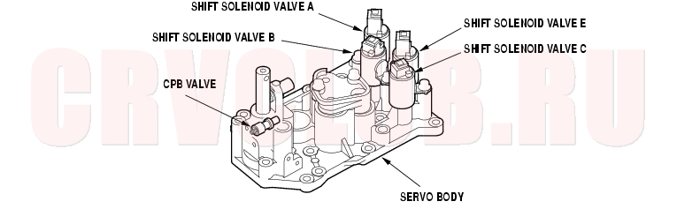
Servo Body
The servo body contains the servo valve, the clutch pressure back-up (CPB) valve, accumulators for 2nd, 3rd, and 4th, and shift solenoid valves for A, B, C, and E.
Accumulator
The accumulators are located in the regulator valve body and the servo body. The regulator valve body contains the 1st accumulator, and the servo body contains the 2nd, 3rd, and 4th accumulators.
14-45
Hydraulic Flow
Distribution of Hydraulic Pressure
As the engine turns, the ATF pump starts to operate. Automatic transmission fluid (ATF) is drawn through the ATF strainer (filter) and discharged into the hydraulic circuit. Then, ATF flowing from the ATF pump becomes line pressure that's regulated by the regulator valve. Torque converter pressure from the regulator valve enters the torque converter through the lock-up shift valve, and it is discharged from the torque converter. The torque converter check valve prevents torque converter pressure from rising.
The PCM controls the shift solenoid valves ON and OFF. The shift valve intercepts line pressure from the ATF pump via the manual valve when the shift solenoid valve is OFF. When the shift solenoid valve is turned ON, line pressure changes to shift solenoid valve pressure at the shift solenoid valve, then the solenoid valve pressure flows to the shift valve. Applying shift solenoid pressure to the shift valves moves the position of the shift valve, and switches the port of the hydraulic circuit. The PCM also controls A/T clutch pressure control solenoid valves A, B, and C. The A/T clutch pressure control solenoid valves regulate hydraulic pressure, and apply the pressure to the clutches for engaging smoothly. The clutches are received optimum clutch pressure which is regulated by the A/T clutch pressure control solenoid valves for comfortable driving and shifting under all conditions.
System Description (cont'd)14-46
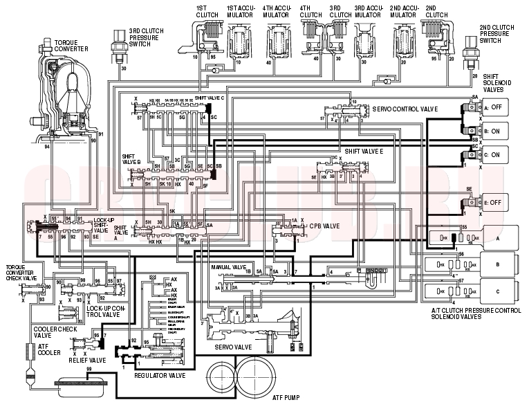
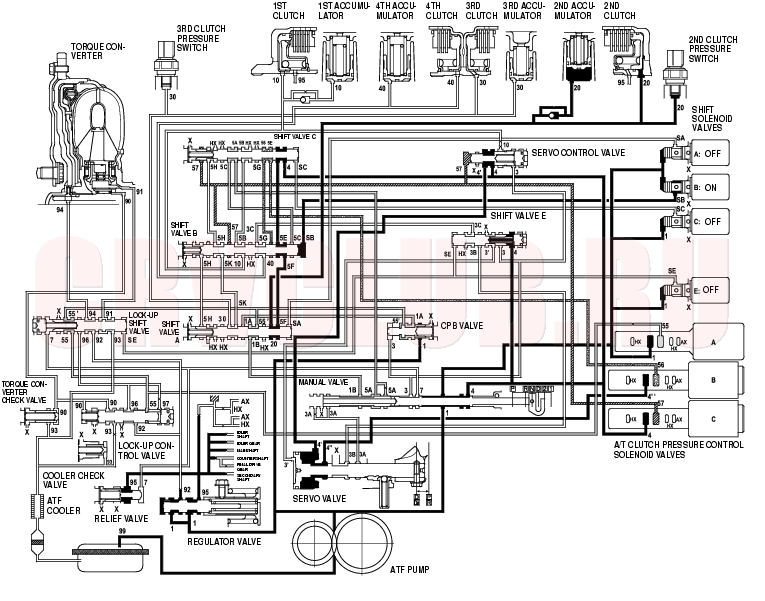
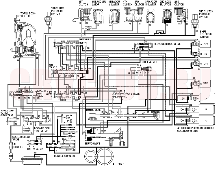
[N] Position
The PCM controls the shift solenoid valves. The conditions of the shift solenoid valves and positions of the shift valves are as follows:
Shift solenoid valve A: OFF Shift valve A remains in right side Shift solenoid valve B: ON Shift valve B moves to left side Shift solenoid valve C: ON Shift valve C moves to left side Shift solenoid valve E: OFF Shift valve E remains in left side Line pressure (1) flows to the shift solenoid valves and the A/T clutch pressure control solenoid valve A, and changes to A/T clutch pressure control solenoid valve A pressure (55) at the A/T clutch pressure control solenoid valve A. A/T clutch pressure control solenoid valve A pressure (55) becomes to line pressure (1B) at the shift valve A, and stops at the manual valve. Under this condition, hydraulic pressure is not applied to the clutches.
NOTE: When used, ''left'' or ''right'' indicates direction on the hydraulic circuit.
14-47
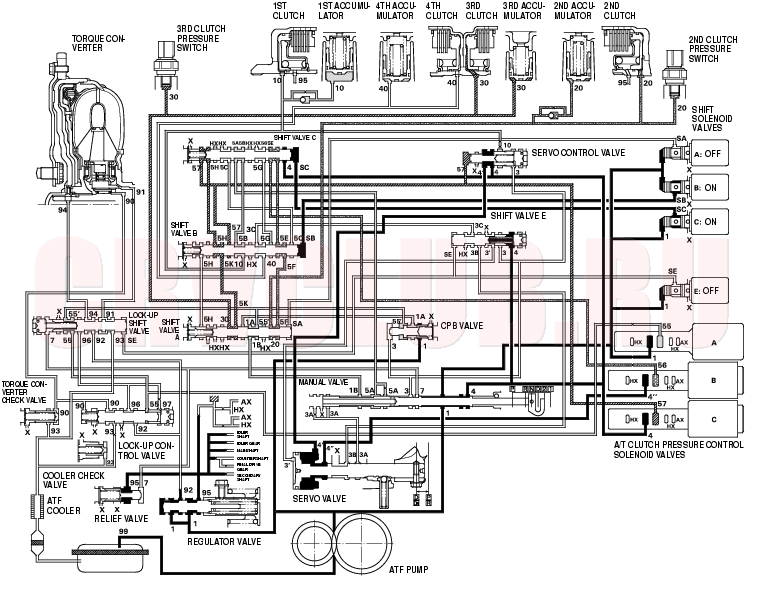
[D] Position: 1st gear shifting from [N] position
Shift solenoid valves remain the same as in [N] position, when shifting to [D] position from [N]. The manual valve is moved to [D] position, and switches the port of line pressure (4) leading to the A/T clutch pressure control solenoid valves. Hydraulic pressure line to the 1st clutch from the A/T clutch pressure control solenoid valve A is created as shift solenoid valve A is OFF, B and C remain ON. A/T clutch pressure control solenoid valve A pressure (55) changes to 1st clutch pressure (10) at the shift valve B, and flows to the 1st clutch. A/T clutch pressure control solenoid valves B and C pressures also flow to the 2nd and 3rd clutches. The 2nd and 3rd clutch engagement reduces 1st clutch engaging shock. The 1st clutch is engaged gently when shifting to [D] position from [N].
NOTE: When used, ''left'' or ''right'' indicates direction on the hydraulic circuit.
System Description (cont'd)14-48
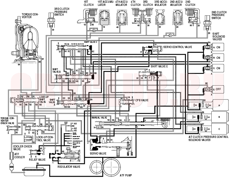
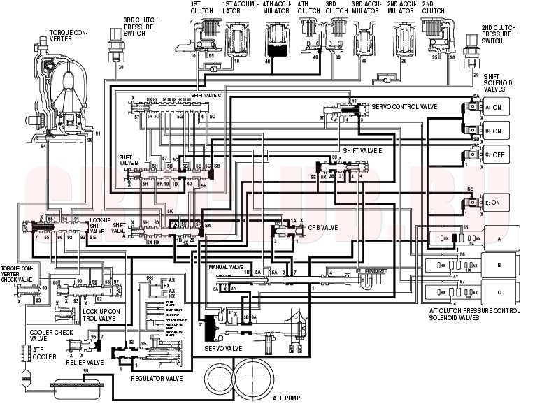
[D] Position: Driving in 1st gear
The PCM turns shift solenoid valves A ON, and remains B and C ON, E OFF. Shift solenoid valve A pressure (SA) is applied to the right side of the shift valve A. The shift valve A is moved to the left side to uncover the port of line pressure leading to the 1st clutch, and to cover the ports of A/T clutch pressure control solenoid valve pressures. Then A/T clutch pressure control solenoid valves pressures are released at the shift valve A.
Fluid flows to the 1st clutch by way of:
Line pressure (1) A/T clutch pressure control solenoid valve A - A/T clutch pressure control solenoid valve A pressure (55)
CPB valve - Line pressure (1A)
The 1st clutch pressure (10) is applied to the 1st clutch, and the 1st clutch is engaged securely.
NOTE: When used, ''left'' or ''right'' indicates direction on the hydraulic circuit.
14-49
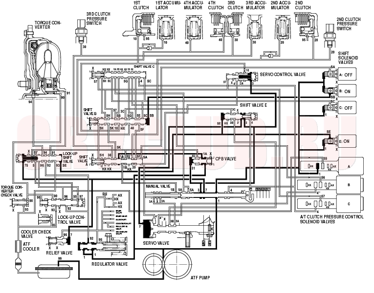
[D] Position: Shifting between 1st gear and 2nd gear
As the speed of the vehicle reaches the prescribed value, the PCM turns shift solenoid valves A OFF, and remains B and C ON, E OFF. Shift solenoid valve A pressure (SA) in the right side of the shift valve A is released. The shift valve A is moved to the right side to uncover the ports of A/T clutch pressure control solenoid valves pressures leading to the 1st, 2nd, and 3rd clutches. The PCM controls the A/T clutch pressure control solenoid valves to regulate hydraulic pressure. A/T clutch pressure control solenoid valve B pressure (56) changes to 2nd clutch pressure (20) at the shift valve A, and flows to the 2nd clutch. The 2nd clutch is engaged gently.
NOTE: When used, ''left'' or ''right'' indicates direction on the hydraulic circuit.
System Description (cont'd)14-50
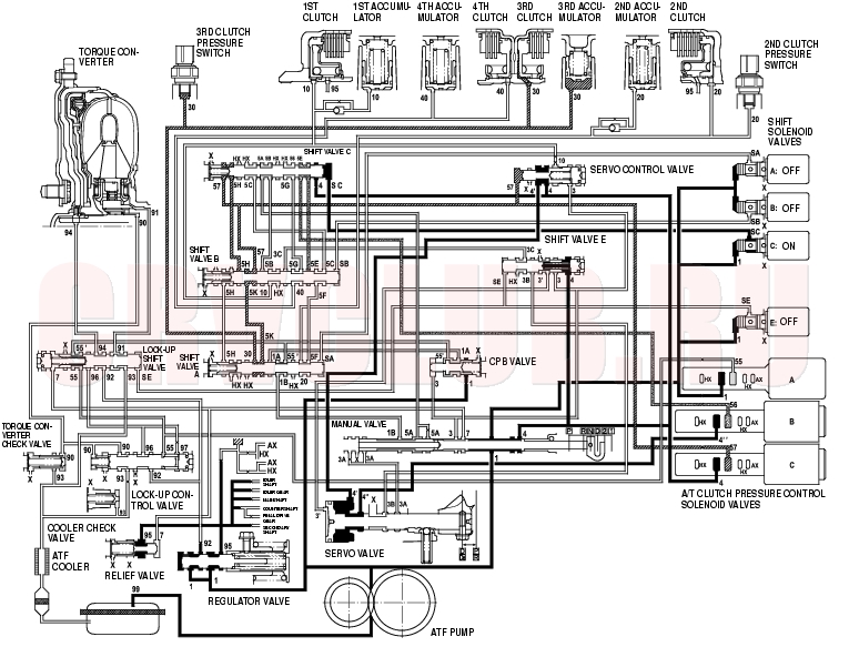
[D] Position: Driving in 2nd gear
The PCM turns shift solenoid valves C OFF and remains A and E OFF, B ON. Shift solenoid valve C pressure (SC) in the right side of the shift valve C is released. The shift valve C is moved to the right side to switch the ports. This movement covers A/T clutch pressure control solenoid valves pressures to stop at the shift valve C and B, and uncover the port of line pressure leading to the 2nd clutch.
Fluid flows to 2nd clutch by way of:
Line pressure (1)
The 2nd clutch pressure (20) is applied to the 2nd clutch, and the 2nd clutch is engaged securely.
NOTE: When used, ''left'' or ''right'' indicates direction on the hydraulic circuit.
14-51
[D] Position: Shifting between 2nd gear and 3rd gear
As the speed of the vehicle reaches the prescribed value, the PCM turns shift solenoid valves C ON, and remains A and E OFF, B ON. Shift solenoid valve C pressure (SC) is applied to the right side of the shift valve C. The shift valve C is moved to the left side to uncover the ports of A/T clutch pressure control solenoid valves pressures leading to the 1st, 2nd, and 3rd clutches. The PCM controls the A/T clutch pressure control solenoid valves to regulate hydraulic pressure. A/T clutch pressure control solenoid valve B pressure (56) changes to 2nd clutch pressure (20) at the shift valve A, and A/T clutch pressure control solenoid valve C pressure (57) changes to 3rd clutch pressure (30) at the shift valve A. The 2nd and 3rd clutches are engaged gently.
NOTE: When used, ''left'' or ''right'' indicates direction on the hydraulic circuit.
System Description (cont'd)14-52
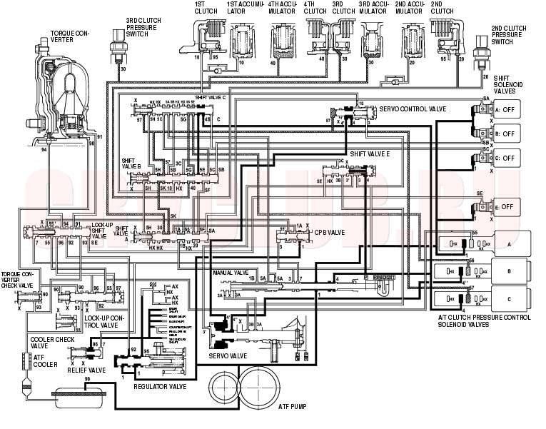
[D] Position: Driving in 3rd gear
The PCM turns shift solenoid valves B OFF, and remains A and E OFF, C ON. Shift solenoid valve B pressure (SB) in the right side of the shift valve B is released, and the shift valve B is moved to the right side. This movement switches the port of A/T clutch pressure control solenoid valve C pressure leading to the 3rd clutch.
A/T clutch pressure control solenoid valve C pressure (57) changes to (5K) at the shift valve B, and becomes to 3rd clutch pressure (30) at the shift valve A. The 3rd clutch pressure (30) is applied to the 3rd clutch, and the 3rd clutch is engaged securely.
NOTE: When used, ''left'' or ''right'' indicates direction on the hydraulic circuit.
14-53
[D] Position: Shifting between 3rd gear and 4th gear
As the speed of the vehicle reaches the prescribed value, the PCM turns shift solenoid valves C OFF, and remains A, B and E OFF. Shift solenoid valve C pressure (SC) in the right side of the shift valve C is released. The shift valve C is moved to the right side to uncover the ports of A/T clutch pressure control solenoid valves A and B pressures leading to the 2nd and 4th clutches. The PCM controls the A/T clutch pressure control solenoid valves to regulate hydraulic pressure. A/T clutch pressure control solenoid valve A pressure changes to 2nd clutch pressure (20) at the shift valve A, and A/T clutch pressure control solenoid valve B pressure changes to 4th clutch pressure (40) at the shift valve B. The 3rd clutch pressure is regulated to low by the A/T clutch pressure control solenoid valve C. The 3rd and 4th clutches are engaged gently.
NOTE: When used, ''left'' or ''right'' indicates direction on the hydraulic circuit.
System Description (cont'd)14-54
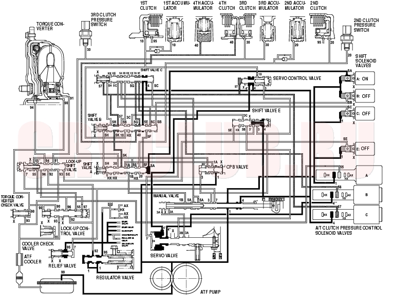
[D] Position: Driving in 4th gear
The PCM turns shift solenoid valves A ON, and remains B, C and E OFF. Shift solenoid valve A pressure (SA) is applied to the right side of the shift valve A. The shift valve A is moved to the left side to cover the ports of A/T clutch pressure control solenoid valves A and C pressure leading to the 2nd and 3rd clutches.
A/T clutch pressure control solenoid valve B pressure (56) changes to (5G) at the shift solenoid valve C, and becomes to 4th clutch pressure (40) at the shift valve B. The 4th clutch pressure (40) is regulated to high by the A/T clutch pressure control solenoid valve B, and the 4th clutch is engaged securely.
NOTE: When used, ''left'' or ''right'' indicates direction on the hydraulic circuit.
14-55
[2] Position
The PCM controls the shift solenoid valves. The conditions of the shift solenoid valves and positions of the shift valves are as follows:
Shift solenoid valve A: OFF Shift valve A remains in right side Shift solenoid valve B: ON Shift valve B moves to left side Shift solenoid valve C: OFF Shift valve C remains in right side Shift solenoid valve E: OFF Shift valve E remains in left side Line pressure (1) changes (4) at the manual valve, and flows to the shift valve C. Line pressure (4) becomes the 2nd clutch pressure (20) at the shift valve A.
Fluid Flows to 2nd clutch by way of:
Line pressure (1)
The 2nd clutch pressure (20) is applied to the 2nd clutch, and the 2nd clutch is engaged.
NOTE: When used, ''left'' or ''right'' indicates direction on the hydraulic circuit.
System Description (cont'd)14-56
[1] Position
The PCM controls the shift solenoid valves. The conditions of the shift solenoid valves and positions of the shift valves are as follows:
Shift solenoid valve A: ON Shift valve A moves to left side Shift solenoid valve B: ON Shift valve B moves to left side Shift solenoid valve C: ON Shift valve C moves to left side Shift solenoid valve E: OFF Shift valve E remains in left side Line pressure (1) flows to the shift solenoid valves and the A/T clutch pressure control solenoid valve A, and changes to A/T clutch pressure control solenoid pressure (55) at the A/T clutch pressure control solenoid valve A.
Fluid Flows to 1st clutch by way of:
A/T clutch pressure control solenoid pressure (55)
The 1st clutch pressure (10) is applied to the 1st clutch, and the 1st clutch is engaged.
NOTE: When used, ''left'' or ''right'' indicates direction on the hydraulic circuit.
14-57
[R] Position: Shifting to [R] position from [P] or [N] position
When shifting in [R] position, the PCM turns shift solenoid valves B and E ON, A and C OFF. Shift solenoid valve B pressure (SB) is applied to the right side of the shift valve B, and the shift valve B is moved to left side. Shift solenoid valve E pressure (SE) is applied to the left side of the shift valve E, and the shift valve E is moved to the right side. Line pressure (1) changes to (3) at the manual valve, and flows to the servo valve via the shift valve E. The servo valve is moved to reverse range position. Movement of the shift valves B and E, and servo valve creates 4th clutch pressure line between the 4th clutch and the A/T clutch pressure control solenoid valve A. The 4th clutch pressure (40) is applied to the 4th clutch, and the 4th clutch is engaged gently.
NOTE: When used, ''left'' or ''right'' indicates direction on the hydraulic circuit.
System Description (cont'd)14-58
[R] Position: Driving in reverse gear
After starting off in reverse gear, the PCM turns shift solenoid valves A ON, and remains B and E ON, C OFF. Shift solenoid valve A pressure (SA) is applied to the right side of the shift valve A to cover the port of A/T clutch pressure control solenoid valve A pressure, and to uncover the port of line pressure leading to the 4th clutch creating full line pressure. The 4th clutch is engaged securely with line pressure.
Reverse Inhibitor Control
While the vehicle is moving forward, the PCM controls shift solenoid valve E remaining OFF. The shift valve E covers the port of line pressure (3') leading to the servo valve reverse position. The servo valve cannot be shifted to reverse position, and hydraulic pressure is not applied to the 4th clutch from servo valve for reverse, as a result, power is not transmitted to the reverse direction.
NOTE: When used, ''left'' or ''right'' indicates direction on the hydraulic circuit.
14-59
[P] Position
Shift solenoid valves B and E are turned ON, and A, and C OFF by the PCM. Line pressure (1) flows to the shift solenoid valves and the A/T clutch pressure control solenoid valve A. Line pressure (3) changes to (3') at the shift valve E, and flows to the servo valve. The servo valve is moved to reverse/park position. Hydraulic pressure is not applied to the clutches.
System Description (cont'd)14-60
Lock-up System
The lock-up mechanism of the torque converter clutch operates in [D] position (3rd and 4th) and [D] position over-drive off mode (3rd). The pressurized fluid is drained from the back of the torque converter through a fluid passage, causing the torque converter clutch piston to be held against the torque converter cover. As this takes place, the mainshaft rotates at the same speed as the engine crankshaft. Together with the hydraulic control, the PCM optimizes the timing and volume of the lock-up mechanism. When the shift solenoid valve E is turned on by the PCM, shift solenoid valve E pressure switch the lock-up shift valve lock-up on and off. The A/T clutch pressure control solenoid valve A and the lock-up control valve control the volume of the lock-up conditions.
Torque Converter Clutch Lock-up ON (Engaging Torque Converter Clutch)
Fluid in the chamber between the torque converter cover and the torque converter clutch piston is drained off, and fluid entered from the chamber between the pump and stator exerts pressure through the torque converter clutch piston against the torque converter cover. The torque converter clutch piston engages with the torque converter cover; torque converter clutch lock-up ON, and the mainshaft rotates at the same as the engine.
Torque Converter Clutch Lock-up OFF (Disengaging Torque Converter Clutch)
Fluid entered from the chamber between the torque converter cover and the torque converter clutch piston passes through the torque converter and goes out from the chambers between the turbine and the stator, and between the pump and the stator. As a result, the torque converter clutch piston moves away from the torque converter, and the torque converter clutch lock-up is released; torque converter clutch lock-up OFF.
14-61
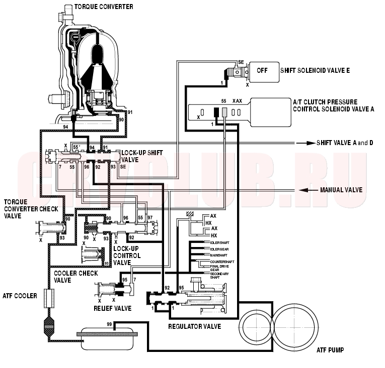
No Lock-up
Shift solenoid valve E is turned OFF by the PCM, and shift solenoid valve E pressure (SE) is not applied to the lock-up shift valve. The lock-up shift valve stays in the right side to uncover the ports of torque converter pressure leading to the left side of the torque converter and releasing from the right side of the torque converter. Torque converter pressure (92) changes to (94) at the lock-up shift valve, and enters into the left side of the torque converter to disengage the torque converter clutch. The torque converter clutch piston keeps away from the torque converter cover, the torque converter clutch lock-up is OFF.
NOTE: When used, ''left'' or ''right'' indicates direction on the hydraulic circuit.
System Description (cont'd)14-62
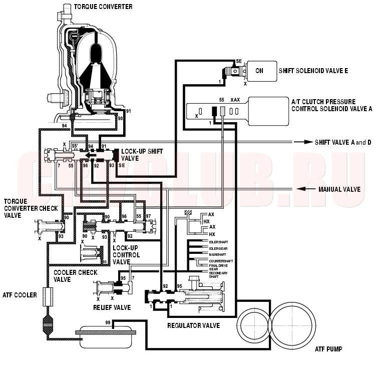
Partial Lock-up
As the speed of the vehicle reaches the prescribed value, shift solenoid valve E is turned ON by the PCM, and shift solenoid valve E pressure (SE) is applied to the right side of the lock-up shift valve. The lock-up shift valve is moved to the left side to switch the port of torque converter pressure (91) leading to the right side of the torque converter, and the port of torque converter pressure (94) releasing from the left side of the torque converter. Torque converter pressure (91) flows to the right side of the torque converter to engage the torque converter clutch. The PCM also controls the A/T clutch pressure control solenoid valve A to regulate A/T clutch pressure control solenoid valve A pressure (55) applying to the lock-up shift valve and lock-up control valve. The position of the lock-up control valve depends on A/T clutch pressure control solenoid valve A pressure (55) and torque converter pressure released from the torque converter. The lock-up control valve controls volume of the torque converter clutch lock-up conditions until fluid between the clutch piston and torque converter cover is released fully; the torque converter clutch partial lock-up condition.
NOTE: When used, ''left'' or ''right'' indicates direction on the hydraulic circuit.
14-63
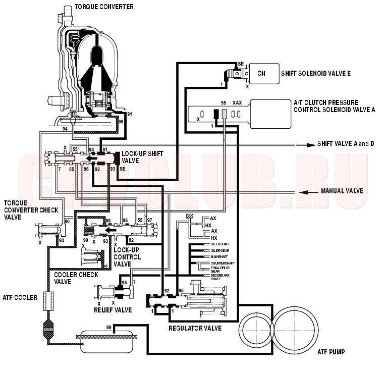
Full Lock-up
When the vehicle speed further increased, the PCM controls the A/T clutch pressure control solenoid valve A to increase A/T clutch pressure control solenoid valve A pressure (55), and the lock-up control valve is moved to the left by pressure increased amount. Torque converter pressure (94) from the left side of the torque converter is released fully at the lock-up control valve, and torque converter pressure (91) engages the torque converter clutch securely; the torque converter clutch full lock-up condition.
NOTE: When used, ''left'' or ''right'' indicates direction on the hydraulic circuit.
System Description (cont'd)14-64
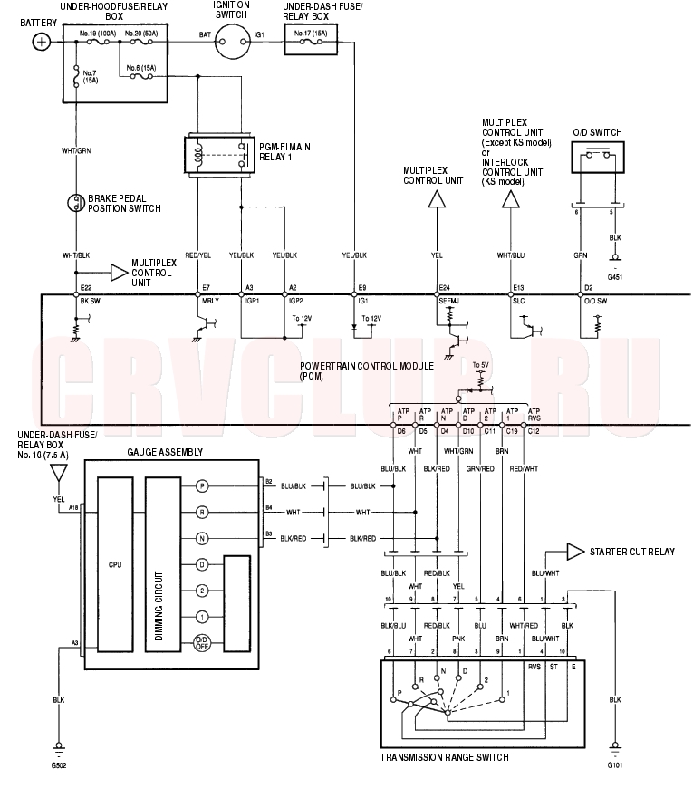
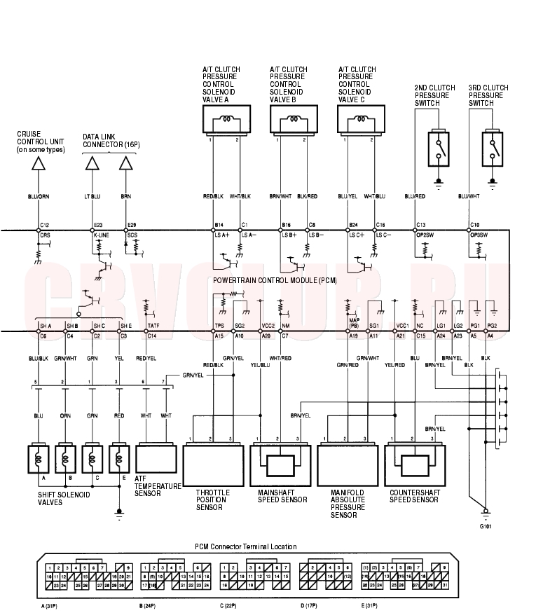
Circuit Diagram - PCM A/T Control System
14-65
DTC Troubleshooting14-66
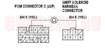
DTC P0710: Problem in ATF Temperature Sensor Circuit
NOTE: Record all freeze data before you troubleshoot.
- Turn the ignition switch OFF.
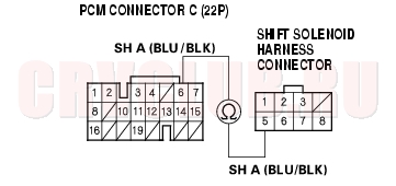
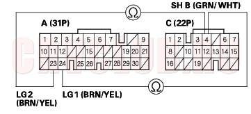
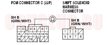
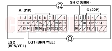
- Disconnect the shift solenoid harness connector.
- Turn the ignition switch ON (II).
- Measure the voltage between the No. 6 terminal of the shift solenoid harness connector and body ground.
Is there about 5 V?
Yes : Go to step 5.
No : Go to step 15.
- Turn the ignition switch OFF.
- Disconnect the battery nagative terminal.
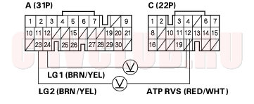
- Disconnect PCM connector A (31P).
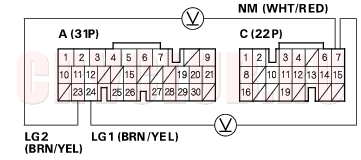
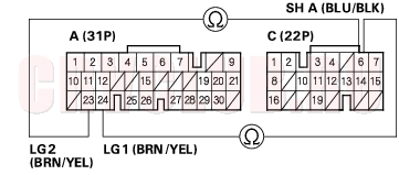
- Check for continuity between the No. 7 terminal of the shift solenoid harness connector and body ground.
Is there continuity?
Yes : Repair short in the wire between PCM connector terminal A10 and the shift solenoid harness connector.

No : Go to step 9.
- Connect PCM connector A (31P).
- Connect the battery nagative terminal.
- Turn the ignition switch ON (II).
14-67
Is there about 5 V?
Yes : Check the ATF temperature sensor and shift solenoid harness in the transmission housing (see page 14-122).
No : Go to step 13.
- Turn the ignition switch OFF.
- Check for continuity between the No. 7 terminal of the shift solenoid harness connector and body ground.
Is there continuity?
Yes : Check for loose terminal fit in the PCM connectors. If necessary, substitute a known-good PCM and recheck.
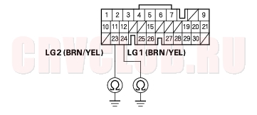
No : Repair open in the wire between PCM connector terminal A10 and the shift solenoid harness connector, or between PCM connector terminals A23 and ground (G101), between A24 and ground (G101), and repair poor ground (G101).
Is there about 5 V?
Yes : Repair open in the wire between PCM connector terminal C14 and the shift solenoid harness connector.
No : Check for a short in the wire between PCM connector terminal C14 and the shift solenoid harness connector. If the wire is OK, check for loose terminal fit in the PCM connectors. If necessary, substitute a known-good PCM and recheck.
DTC Troubleshooting (cont'd)14-68
DTC P0715: Problem in Mainshaft Speed Sensor Circuit
NOTE: Record all freeze data before you troubleshoot.
Is there any fuel and emissions DTC?
Yes : Perform the troubleshooting flowchart for the indicated code(s). Recheck for code P0715 after troubleshooting.
No : Go to step 2.
- Turn the ignition switch OFF.
- Disconnect the battery negative terminal.
- Disconnect PCM connector A (31P).
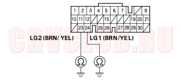
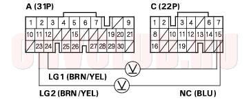
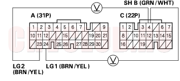
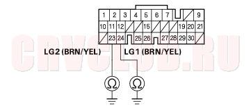
- Check for continuity between PCM connector terminals A23 and body ground, and between A24 and body ground.
Is there continuity?
Yes : Go to step 6.
No : Repair open in the wires between PCM connector terminals A23 and ground (G101), between A24 and ground (G101), and repair poor ground (G101).
- Connect PCM connector A (31P).
- Connect the battery negative terminal.
- Disconnect the mainshaft speed sensor connector.
- Turn the ignition switch ON (II).
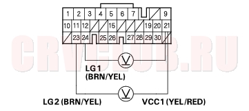
- Measure the voltage between the No. 1 terminal of the mainshaft speed sensor connector and body ground.
Is there about 5 V?
Yes : Go to step 11.
No : Go to step 20.
- Turn the ignition switch OFF.
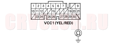
- Check for continuity between the No. 2 terminal of the mainshaft speed sensor connector and body ground.
Is there continuity?
Yes : Repair short to ground in the wire between PCM connector terminal C7 and mainshaft speed sensor connector.
No : Go to step 13.
14-69
- Check for continuity between the No. 3 terminal of the mainshaft speed sensor connector and body ground.
Is there continuity?
Yes : Go to step 14.
No : Repair open in the wire between the mainshaft speed sensor connector and ground (G101).
- Turn the ignition switch ON (II).
- Measure the voltage between the No. 2 and No. 3 terminals of the mainshaft speed sensor connector.
Is there about 5 V?
Yes : Go to step 16.
No : Go to step 25.
- Connect the mainshaft speed sensor connector.
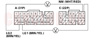
- Measure the voltage between PCM connector terminals C7 and A23 or A24.
Is the voltage 0 V or about 5 V?
Yes : Go to step 18.
No : Replace the mainshaft speed sensor.
- Shift to [P] position. Start the engine, and run it idle.
- With engine idling, measure the voltage between PCM connector terminals C7 and A23 or A24.
Is there 1.5 V - 3.5 V?
Yes : Check for loose terminal fit in the PCM connectors. If necessary, substitute a known-good PCM and recheck.
No : Replace the mainshaft speed sensor.
DTC Troubleshooting (cont'd)14-70
Is there 4.75 V - 5.25 V?
Yes : Repair open in the wire between PCM connector terminal A20 and the mainshaft speed sensor connector.
No : Go to step 21.
- Turn the ignition switch OFF.
- Disconnect the battery negative terminal.
- Disconnect PCM connector A (31P).
- Check for continuity between PCM connector A20 and body ground.
Is there continuity?
Yes : Repair short to ground in the wire between PCM connector terminal A20 and the mainshaft speed sensor connector.
No : Check for loose terminal fit in the PCM connectors. If necessary, substitute a known-good PCM and recheck.
Is there about 5 V?
Yes : Repair open in the wire between PCM connector C7 and the mainshaft speed sensor connector.
No : Check for loose terminal fit in the PCM connectors. If necessary, substitute a known-good PCM and recheck.
14-71
DTC P0720: Problem in Countershaft Speed Sensor Circuit
NOTE: Record all freeze data before you troubleshoot.
Is there any fuel and emissions DTC?
Yes : Perform the troubleshooting flowchart for the indicated code(s). Recheck for code P0720 after troubleshooting.
No : Go to step 2.
- Turn the ignition switch OFF.
- Disconnect the battery negative terminal.
- Disconnect PCM connector A (31P).
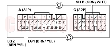
- Check for continuity between PCM connector terminals A23 and body ground, and between A24 and body ground.
Is there continuity?
Yes : Go to step 6.
No : Repair open in the wires between PCM connector terminals A23 and ground (G101), between A24 and ground (G101), and repair poor ground (G101).
- Connect PCM connector A (31P).
- Connect the battery negative terminal.
- Disconnect the countershaft speed sensor connector.
- Turn the ignition switch ON (II).
- Measure the voltage between the No. 1 terminal of the countershaft speed sensor connector and body ground.
Is there about 5 V?
Yes : Go to step 11.
No : Go to step 21.
- Turn the ignition switch OFF.
- Check for continuity between the No. 2 terminal of the countershaft speed sensor connector and body ground.
Is there continuity?
Yes : Repair short to ground in the wire between PCM connector terminal C15 and the countershaft speed sensor connector.
No : Go to step 13.
DTC Troubleshooting (cont'd)14-72
- Check for continuity between the No. 3 terminal of the countershaft speed sensor connector and body ground.
Is there continuity?
Yes : Go to step 14.
No : Repair open in the wire between the countershaft speed sensor connector and ground (G101).
- Turn the ignition switch ON (II).
- Measure the voltage between the No. 2 and No. 3 terminals of the countershaft speed sensor connector.
Is there about 5 V?
Yes : Go to step 16.
No : Go to step 26.
- Connect the countershaft speed sensor connector.
- Measure the voltage between PCM connector terminals C15 and A23 or A24.
Is the voltage 0 V or about 5 V?
Yes : Go to step 18.
No : Replace the countershaft speed sensor.
14-73
- For 4WD model: Raise the vehicle, make sure it is securely supported, and allow the all four wheels to rotate freely.
For 2WD model: Raise the front of the vehicle, make sure it is securely supported, and allow the front wheels to rotate freely.
- Start the engine, then shift to [D] position and drive the vehicle.
- Measure the voltage between PCM connector terminals C15 and A23 or A24.
Is there 1.5 V - 3.5 V?
Yes : Check for loose terminal fit in the PCM connectors. If necessary, substitute a known-good PCM and recheck.
No : Replace the countershaft speed sensor.
Is there 4.75 V - 5.25 V?
Yes : Repair open in the wire between PCM connector terminal A21 and the countershaft speed sensor connector.
No : Go to step 22.
DTC Troubleshooting (cont'd)14-74
- Turn the ignition switch OFF.
- Disconnect the battery negative terminal.
- Disconnect PCM connector A (31P).
- Check for continuity between PCM connector terminal A21 and body ground.
Is there continuity?
Yes : Repair short to ground in the wire between PCM connector terminal A21 and the countershaft speed sensor connector.
No : Check for loose terminal fit in the PCM connectors. If necessary, substitute a known-good PCM and recheck.
Is there about 5 V?
Yes : Repair open in the wire between PCM connector terminal C15 and the countershaft speed sensor connector.
No : Check for loose terminal fit in the PCM connectors. If necessary, substitute a known-good PCM and recheck.
14-75
DTC P0745: Problem in Hydraulic Control System of A/T Clutch Pressure Control Solenoid Valve A Circuit
NOTE: Record all freeze data before you troubleshoot.
Is there any of the DTC?
Yes : Perform the troubleshooting flowchart for the indicated code(s). Turn the ignition switch OFF, and go to step 4 after troubleshooting.
No : Go to step 2.
- Turn the ignition switch OFF.
- Replace the A/T clutch pressure control solenoid valve A (see page 14-117) .
- Reset the PCM memory by removing the No. 6 ECU fuse (15A) in the under-hood fuse/relay box for more than 10 seconds.
- Start the engine, and shift to [1] position. Start the vehicle off in [1] position, drive at 19 mph (30 km/h) for 10 seconds, shift into [2] position, drive at 19 mph (30 km/h) for 10 seconds, then decelerate to a stop.
- Repeat step 5 to test-drive the vehicle.
- Recheck for DTC P0745.
Is DTC P0745 indicated?
Yes : Replace the transmission assembly.
No : The problem has been corrected.
DTC Troubleshooting (cont'd) 14-76
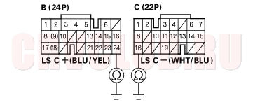
DTC P0748: Problem in A/T Clutch Pressure Control Solenoid Valve A Circuit
NOTE: Record all freeze data before you troubleshoot.
- Disconnect the A/T clutch pressure control solenoid valve A connector.
- Measure A/T clutch pressure control solenoid valve A resistance at the solenoid valve connector terminals.
Is there about 5
?
Yes : Go to step 3.
No : Replace the A/T clutch pressure control solenoid valve A.
- Disconnect the battery negative terminal.
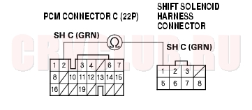
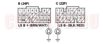
- Disconnect PCM connectors B (24P) and C (22P).
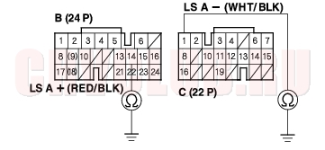
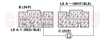
- Check for continuity between PCM connector terminals B14 and body ground, and between C1 and body ground.
Is there continuity?
Yes : Repair short to ground in the wires between PCM connector terminals B14 and the A/T clutch pressure control solenoid valve A, and between C1 and the solenoid valve A.
No : Go to step 6.
14-77
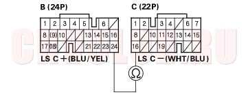
- Connect the A/T clutch pressure control solenoid valve A connector.
- Measure the resistance between PCM connector terminals B14 and C1.
Is there about 5
Yes : Go to step 8.
No : Repair loose terminal or open in the wires between PCM connector terminals B14 and the A/T clutch pressure control solenoid valve A, and between C1 and the solenoid valve A.
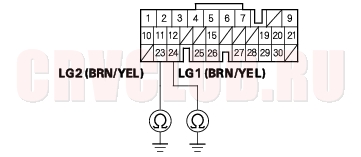
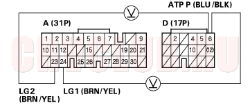
- Disconnect PCM connector A (31P).
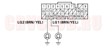
- Check for continuity between PCM connector terminals A23 and body ground, and between A24 and body ground.
Is there continuity?
Yes : Check for loose terminal fit in the PCM connectors. If necessary, substitute a known-good PCM and recheck.
No : Repair open in the wires between PCM connector terminals A23 and ground (G101), and between A24 and ground (G101), and repair poor ground (G101).
DTC Troubleshooting (cont'd)14-78
DTC P0750: Problem in Hydraulic Control System of Shift Solenoid Valve A Circuit
NOTE: Record all freeze data before you troubleshoot.
Is there any of the DTC?
Yes : Perform the troubleshooting flowchart for the indicated code(s). Turn the ignition switch OFF, and go to step 4 after troubleshooting.
No : Go to step 2.
- Turn the ignition switch OFF.
- Replace the shift solenoid valve A (see page 14-114) .
- Reset the PCM memory by removing the No. 6 ECU fuse (15 A) in the under-hood fuse/relay box for more than 10 seconds.
- Start the engine, and shift to [1] position. Start the vehicle off in [1] position, drive at 25 mph (40 km/h) for 10 seconds, shift into [2] position, drive at 25 mph (40 km/h) for 10 seconds, then shift into [1] position, and drive at 25 mph (40 km/h) for 10 seconds.
- Recheck for DTC P0750.
Is DTC P0750 indicated?
Yes : Go to step 7.
No : The problem has been corrected.
- Turn the ignition switch OFF.
- Remove the transmission, and overhaul transmission hydraulic control system and the 2nd clutch line.
- Install the transmission on the vehicle.
- Reset the PCM memory by removing the No. 6 ECU fuse (15 A) in the under-hood fuse/relay box for more than 10 seconds, if necessary.
- Start the engine, and shift to [1] position. Start the vehicle off in [1] position, drive at 25 mph (40 km/h) for 10 seconds, shift into [2] position, drive at 25 mph (40 km/h) for 10 seconds, then shift into [1] position, and drive at 25 mph (40 km/h) for 10 seconds.
- Recheck for DTC P0750.
Is DTC P0750 indicated?
Yes : Replace the transmission assembly.
No : The problem has been corrected.
14-79
DTC P0753: Problem in Shift Solenoid Valve A Circuit
NOTE: Record all freeze data before you troubleshoot.
- Turn the ignition switch OFF.
- Disconnect the battery negative terminal.
- Disconnect PCM connectors A (31P) and C (22P).
- Reconnect the battery negative terminal.
- Turn the ignition switch ON (II).
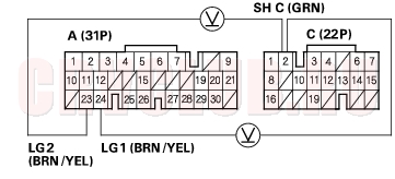
- Measure the voltage between PCM connector terminals C6 and A23 or A24.
Is there voltage?
Yes : Repair short to power in the wire between PCM connector terminal C6 and the shift solenoid valve A.
No : Go to step 7.
- Turn the ignition switch OFF.
- Disconnect the shift solenoid harness connector at the transmission housing.
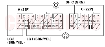
- Check for continuity between PCM connector terminals C6 and A23 or A24.
Is there continuity?
Yes : Repair short to ground in the wire between PCM connector terminal C6 and the shift solenoid harness connector.
No : Go to step 10.
- Connect the shift solenoid harness connector.
- Measure the resistance between PCM connector terminals C6 and A23 or A24.
Is there 12 - 25
Yes : Check for loose terminal fit in the PCM connectors. If necessary, substitute a known-good PCM and recheck.
No : Go to step 12.
DTC Troubleshooting (cont'd)14-80
- Disconnect the shift solenoid harness connector.
- Check for continuity between PCM connector terminal C6 and the No. 5 terminal of the shift solenoid harness connector.
Is there continuity?
Yes : Check the shift solenoid valve A, and check for an open in the shift solenoid harness in the transmission (see page 14-112).
No : Repair open in the wire between PCM connector terminal C6 and the shift solenoid harness connector.
14-81
DTC P0758: Problem in Shift Solenoid Valve B Circuit
NOTE: Record all freeze data before you troubleshoot.
- Turn the ignition switch OFF.
- Disconnect the battery negative terminal.
- Disconnect PCM connectors A (31P) and C (22P).
- Reconnect the battery negative terminal.
- Turn the ignition switch ON (II).
- Measure the voltage between PCM connector terminals C4 and A23 or A24.
Is there voltage?
Yes : Repair short to power in the wire between PCM connector terminal C4 and the shift solenoid valve B.
No : Go to step 7.
- Turn the ignition switch OFF.
- Disconnect the shift solenoid harness connector at the transmission housing.
- Check for continuity between PCM connector terminals C4 and A23 or A24.
Is there continuity?
Yes : Repair short to ground in the wire between PCM connector terminal C4 and the shift solenoid harness connector.
No : Go to step 10.
- Connect the shift solenoid harness connector.
- Measure the resistance between PCM connector terminals C4 and A23 or A24.
Is there 12 - 25
Yes : Check for loose terminal fit in the PCM connectors. If necessary, substitute a known-good PCM and recheck.
No : Go to step 12.
DTC Troubleshooting (cont'd)14-82
- Disconnect the shift solenoid harness connector.
- Check for continuity between PCM connector terminal C4 and No. 2 terminal of the shift solenoid harness connector.
Is there continuity?
Yes : Check the shift solenoid valve B, and check for an open in the shift solenoid harness in the transmission (see page 14-112).
No : Repair open in the wire between PCM connector terminal C4 and the shift solenoid harness connector.
14-83
DTC P0763: Problem in Shift Solenoid Valve C Circuit
NOTE: Record all freeze data before you troubleshoot.
- Turn the ignition switch OFF.
- Disconnect the battery negative terminal.
- Disconnect PCM connectors A (31P) and C (22P).
- Reconnect the battery negative terminal.
- Turn the ignition switch ON (II).
- Measure the voltage between PCM connector terminals C2 and A23 or A24.
Is there voltage?
Yes : Repair short to power in the wire between PCM connector terminal C2 and the shift solenoid valve C.
No : Go to step 7.
- Turn the ignition switch OFF.
- Disconnect the shift solenoid harness connector at the transmission housing.
- Check for continuity between PCM connector terminals C2 and A23 or A24.
Is there continuity?
Yes : Repair short to ground in the wire between PCM connector terminal C2 and the shift solenoid harness connector.
No : Go to step 10.
- Connect the shift solenoid harness connector.
- Measure the resistance between PCM connector terminals C2 and A23 or A24.
Is there 12 - 25
Yes : Check for loose terminal fit in the PCM connectors. If necessary, substitute a known-good PCM and recheck.
No : Go to step 12.
DTC Troubleshooting (cont'd)14-84
- Disconnect the shift solenoid harness connector.
- Check for continuity between PCM connector terminal C2 and the No. 1 terminal of the shift solenoid harness connector.
Is there continuity?
Yes : Check the shift solenoid valve C, and check for an open in the shift solenoid harness in the transmission (see page 14-112).
No : Repair open in the wire between PCM connector terminal C2 and the shift solenoid harness connector.
14-85
DTC P0773: Problem in Shift Solenoid Valve E Circuit
NOTE: Record all freeze data before you troubleshoot.
- Turn the ignition switch OFF.
- Disconnect the battery negative terminal.
- Disconnect PCM connectors A (31P) and C (22P).
- Reconnect the battery negative terminal.
- Turn the ignition switch ON (II).
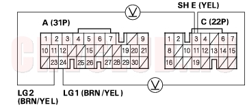
- Measure the voltage between PCM connector terminals C3 and A23 or A24.
Is there voltage?
Yes : Repair short to power in the wire between PCM connector terminal C3 and the shift solenoid valve E.
No : Go to step 7.
- Turn the ignition switch OFF.
- Disconnect the shift solenoid harness connector at the transmission housing.
- Check for continuity between PCM connector terminals C3 and A23 or A24.
Is there continuity?
Yes : Repair short to ground in the wire between PCM connector terminal C3 and the shift solenoid harness connector.
No : Go to step 10.
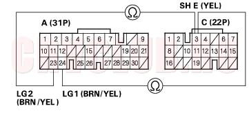
- Connect the shift solenoid harness connector.
- Measure the resistance between PCM connector terminals C3 and A23 or A24.
Is there 12 - 25
Yes : Check for loose terminal fit in the PCM connectors. If necessary, substitute a known-good PCM and recheck.
No : Go to step 12.
DTC Troubleshooting (cont'd)14-86
- Disconnect the shift solenoid harness connector.
- Check for continuity between PCM connector terminal C3 and the No. 3 terminal of the shift solenoid harness connector.
Is there continuity?
Yes : Check the shift solenoid valve E, and check for an open in the shift solenoid harness in the transmission (see page 14-112).
No : Repair open in the wire between PCM connector terminal C3 and the shift solenoid harness connector.
14-87
DTC P0775: Problem in Hydraulic Control System of A/T Clutch Pressure Control Solenoid Valve B Circuit
NOTE: Record all freeze data before you troubleshoot.
Is there any of the DTC?
Yes : Perform the troubleshooting flowchart for the indicated code(s). Turn the ignition switch OFF, and go to step 4 after troubleshooting.
No : Go to step 2.
- Turn the ignition switch OFF.
- Replace the A/T clutch pressure control solenoid valve B (with C as a set) (see page 14-119) .
- Reset the PCM memory by removing the No. 6 ECU (15 A) fuse in the under-hood fuse/relay box for more than 10 seconds.
- Start the engine, and shift to [2] position. Test-drive the vehicle in [2] position at 25 mph (40 km/h) for 10 seconds, shift into [D] position with over-drive OFF mode in 3rd gear, drive at 25 mph (40 km/h) for 10 seconds, then decelerate to a stop. Do not stop the engine. Start off in [1] position, and drive at 19 mph (30 km/h) for 10 seconds.
- Repeat step 5 to test-drive the vehicle.
- Recheck for DTC P0775.
Is DTC P0775 indicated?
Yes : Replace the transmission assembly.
No : The problem has been corrected.
DTC Troubleshooting (cont'd)14-88
DTC P0778: Problem in A/T Clutch Pressure Control Solenoid Valve B Circuit
NOTE: Record all freeze data before you troubleshoot.
- Disconnect the A/T clutch pressure control solenoid valve B connector.
- Measure A/T clutch pressure control solenoid valve B resistance at the solenoid valve connector terminals.
Is there about 5
Yes : Go to step 3.
No : Replace the A/T clutch pressure control solenoid valve B.
- Disconnect the battery negative terminal.
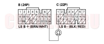
- Disconnect PCM connectors B (24P) and C (22P).
- Check for continuity between PCM connector terminals B16 and body ground, and between C8 and body ground.
Is there continuity?
Yes : Repair short to ground in the wires between PCM connector terminals B16 and the A/T clutch pressure control solenoid valve B, and between C8 and the solenoid valve B.
No : Go to step 6.
14-89
- Connect the A/T clutch pressure control solenoid valve B connector.
- Measure the resistance between PCM connector terminals B16 and C8.
Is there about 5
Yes : Go to step 8.
No : Repair loose terminal or open in the wires between PCM connector terminals B16 and the A/T clutch pressure control solenoid valve B, and between C8 and the solenoid valve B.
- Disconnect PCM connector A (31P).
- Check for continuity between PCM connector terminals A23 and body ground, and between A24 and body ground.
Is there continuity?
Yes : Check for loose terminal fit in the PCM connectors. If necessary, substitute a known-good PCM and recheck.
No : Repair open in the wires between PCM connector terminals A23 and ground (G101), and between A24 and ground (G101), and repair poor ground (G101).
DTC Troubleshooting (cont'd)14-90
DTC P0780: Mechanical Problem in Hydraulic Control System
Record all freeze data before you troubleshoot. Keep these replacement solenoid valves on hand: - A/T clutch pressure control solenoid valves A, B and C.
- Shift solenoid valves A, B, C and E.
Is there any of the DTC?
Yes : Perform the troubleshooting flowchart for the indicated code(s). Check for DTC P0780 after troubleshooting.
No : Go to step 2.
- Turn the ignition switch OFF.
- Replace the A/T clutch pressure control solenoid valve A (see page 14-117) .
- Replace the A/T clutch pressure control solenoid valves B and C (see page 14-119) .
- Reset the PCM memory by removing the No. 6 ECU (15A) fuse in the under-hood fuse/relay box for more than 10 seconds.
- Drive the vehicle for several minutes in 1st, 2nd, 3rd and 4th gears in [D] position, and stop the vehicle. Do not stop the engine.
- Repeat step 6 to test-drive the vehicle five times.
- Recheck for DTC P0780.
Is DTC P0780 indicated?
Yes : Go to step 9.
No : The problem has been corrected.
- Turn the ignition switch OFF.
- Replace the shift solenoid valves A, B, C and E (see page 14-114) .
- Reset the PCM memory by removing the No. 6 ECU (15A) fuse in the under-hood fuse/relay box for more than 10 seconds.
- Drive the vehicle for several minutes in 1st, 2nd, 3rd and 4th gears in [D] position, and stop the vehicle. Do not stop the engine.
- Repeat step 12 to test-drive the vehicle five times.
- Recheck for DTC P0780.
Is DTC P0780 indicated?
Yes : Go to step 15.
No : The problem has been corrected.
- Turn the ignition switch OFF.
- Remove the transmission, and overhaul transmission hydraulic control system.
- Install the transmission on the vehicle.
- Reset the PCM memory by removing the No. 6 ECU (15A) fuse in the under-hood fuse/relay box for more than 10 seconds.
- Drive the vehicle for several minutes in 1st, 2nd, 3rd and 4th gears in [D] position, and stop the vehicle. Do not stop the engine.
- Repeat step 19 to test-drive the vehicle five times.
- Recheck for DTC P0780.
Is DTC P0780 indicated?
Yes : Replace the transmission assembly.
No : The problem has been corrected.
14-91
DTC P0795: Problem in Hydraulic Control System of A/T Clutch Pressure Control Solenoid Valve C Circuit
NOTE: Record all freeze data before you troubleshoot.
Is there any of the DTC?
Yes : Perform the troubleshooting flowchart for the indicated code(s). Turn the ignition switch OFF, and go to step 4 after troubleshooting.
No : Go to step 2.
- Turn the ignition switch OFF.
- Replace the A/T clutch pressure control solenoid valve C (with B as a set) (see page 14-119) .
- Reset the PCM memory by removing the No. 6 ECU (15A) fuse in the under-hood fuse/relay box for more than 10 seconds.
- Start the vehicle off in [2] position, accelerate to 25 mph (40 km/h), then shift into [D] position with the O/D switch turned off for over-drive off mode. Drive in 3rd gear at 25 mph (40 km/h) for several seconds, then shift into [2] position and drive at 25 mph (40 km/h) for 10 seconds.
- Recheck for DTC P0795.
Is DTC P0795 indicated?
Yes : Go to step 7.
No : The problem has been corrected.
- Turn the ignition switch OFF.
- Remove the transmission, and overhaul transmission hydraulic control system and the 3rd clutch line.
- Install the transmission on the vehicle.
- Reset the PCM memory by removing the No. 6 ECU (15A) fuse in the under-hood fuse/relay box for more than 10 seconds.
- Start the vehicle off in [2] position, accelerate to 25 mph (40 km/h), then shift into [D] position with the O/D switch turned off for over-drive off mode. Drive in 3rd gear at 25 mph (40 km/h) for several seconds, then shift into [2] position and drive at 25 mph (40 km/h) for 10 seconds.
- Recheck for DTC P0795.
Is DTC P0795 indicated?
Yes : Replace the transmission assembly.
No : The problem has been corrected.
DTC Troubleshooting (cont'd)14-92
DTC P0798: Problem in A/T Clutch Pressure Control Solenoid Valve C Circuit
NOTE: Record all freeze data before you troubleshoot.
- Disconnect the A/T clutch pressure control solenoid valve C connector.
- Measure A/T clutch pressure control solenoid valve C resistance at the solenoid valve connector terminals.
Is there about 5
Yes : Go to step 3.
No : Replace the A/T clutch pressure control solenoid valve C.
- Disconnect the battery negative terminal.
- Disconnect PCM connectors B (24P) and C (22P).
- Check for continuity between PCM connector terminals B24 and body ground, and between C16 and body ground.
Is there continuity?
Yes : Repair short to ground in the wires between PCM connector terminals B24 and the A/T clutch pressure control solenoid valve C, and between C16 and the solenoid valve C.
No : Go to step 6.
14-93
- Connect the A/T clutch pressure control solenoid valve C connector.
- Measure the resistance between PCM connector terminals B24 and C16.
Is there about 5
Yes : Go to step 8.
No : Repair loose terminal or open in the wires between PCM connector terminals B24 and the A/T clutch pressure control solenoid valve C, and between C16 and the solenoid valve C.
- Disconnect PCM connector A (31P).
- Check for continuity between PCM connector terminals A23 and body ground, and between A24 and body ground.
Is there continuity?
Yes : Check for loose terminal fit in the PCM connectors. If necessary, substitute a known-good PCM and recheck.
No : Repair open in the wires between PCM connector terminals A23 and ground (G101), and between A24 and ground (G101), and repair poor ground (G101).
DTC Troubleshooting (cont'd)14-94
DTC P0840: Problem in 2nd Clutch Pressure Switch Circuit
NOTE: Record all freeze data before you troubleshoot.
- Disconnect the 2nd clutch pressure switch.
- Turn the ignition switch ON (II).
- Measure the voltage between PCM connector terminal C13 and body ground.
Is there about 5 V?
Yes : Go to step 4.
No : Check for a short to ground in the wire between PCM connector terminal C13 and the 2nd clutch pressure switch. If wire is OK, check for loose terminal fit in the PCM connectors. If necessary, substitute a known-good PCM and recheck.
Is there about 5 V?
Yes : Go to step 5.
No : Repair open in the wire between PCM connector terminal C13 and the 2nd clutch pressure switch.
- Turn the ignition switch OFF.
- Measure the resistance between the 2nd clutch pressure switch connector terminal and body ground.
Is there 40 M
Yes : Go to step 7.
No : Replace the 2nd clutch pressure switch.
14-95
- Connect the 2nd clutch pressure switch connector.
- Raise the front of the vehicle, make sure it is securely supported, and allow the front wheels to rotate freely.
- Start the engine, and shift into [2] position.
- Drive the vehicle in 2nd gear for more than five seconds.
- With driving in [2] position, measure the voltage between PCM connector terminal C13 and body ground.
Is there 0 V?
Yes : Check for loose terminal fit in the PCM connectors. If necessary, substitute a known-good PCM and recheck.
No : Replace the 2nd clutch pressure switch.
DTC Troubleshooting (cont'd)14-96
DTC P0845: Problem in 3rd Clutch Pressure Switch Circuit
NOTE: Record all freeze data before you troubleshoot.
- Disconnect the 3rd clutch pressure switch.
- Turn the ignition switch ON (II).
- Measure the voltage between PCM connector terminal C10 and body ground.
Is there about 5 V?
Yes : Go to step 4.
No : Check for short to ground in the wire between PCM connector terminal C10 and the 3rd clutch pressure switch. If wire is OK, check for loose terminal fit in the PCM connectors. If necessary, substitute a known-good PCM and recheck.
Is there about 5 V?
Yes : Go to step 5.
No : Repair open in the wire between PCM connector terminal C10 and the 3rd clutch pressure switch.
- Turn the ignition switch OFF.
- Measure the resistance between the 3rd clutch pressure switch connector terminal and body ground.
Is there 40 M
Yes : Go to step 7.
No : Replace the 3rd clutch pressure switch.
14-97
- Connect the 3rd clutch pressure switch connector.
- For 4WD model: Raise the vehicle, make sure it is securely supported, and allow the all four wheels to rotate freely.
For 2WD model: Raise the front of the vehicle, make sure it is securely supported, and allow the front wheels to rotate freely.
- Start the engine. Shift into the [D] position, then turn the O/D switch off for driving with over-drive OFF mode.
- Accelerate the vehicle until the speed exceeds 19 mph (30 km/h), then release the accelerator. Shift into the [N] positon, and return to the [D]; the transmission will shift to 3rd gear.
- Drive the vehicle in 3rd gear for more than 5 seconds.
- With driving in 3rd gear, measure the voltage between PCM connector terminal C10 and body ground.
Is there 0 V?
Yes : Check for loose terminal fit in the PCM connectors. If necessary, substitute a known-good PCM and recheck.
No : Replace the 3rd clutch pressure switch.
DTC Troubleshooting (cont'd)14-98
DTC P1705: Short in Transmission Range Switch Circuit
NOTE: Record all freeze data before you troubleshoot.
- Turn the ignition switch ON (II).
- Observe the A/T gear position indicator while shifting to each position.
Do any indicators stay on when the shift lever is not in that position?
Yes : Go to step 3.
- Turn the ignition switch OFF, then go to step Disconnect the transmission range switch connector, and watch the A/T gear position indicator.
Do all gear position indicators go out?
Yes : Replace the transmission range switch.
No : Turn the ignition switch OFF, then go to step 5.
- Inspect the transmission range switch (see page 14-168) .
Is the switch OK?
Yes : Go to step 5.
No : Replace the transmission range switch.
- Connect the transmission range switch connector.
- Turn the ignition switch ON (II).
- Shift to all positions other than [P].
- Measure the voltage between PCM connector terminals D6 and A23 or A24.
Is there about 5 V?
Yes : Go to step 9.
No : Check for a short in the wire between PCM connector terminal D6 and the transmission range switch or A/T gear position indicator, and check for an open in the wires between ground G101 and PCM connector terminals A23 and A24. If the wires are OK, check for loose terminal fit in the PCM connectors. If necessary, substitute a known-good PCM and recheck.
14-99
- Shift to all positions other than [R].
- Measure the voltage between PCM connector terminals D5 and A23 or A24.
Is there about 5 V?
Yes : Go to step 11.
No : Check for a short in the wire between PCM connector terminal D5 and the transmission range switch or A/T gear position indicator. If the wire is OK, check for loose terminal fit in the PCM connectors. If necessary, substitute a known-good PCM and recheck.
Is there about 5 V?
Yes : Go to step 12.
No : Check for a short in the wire between PCM connector terminal C12 and the transmission range switch. If the wire is OK, check for loose terminal fit in the PCM connectors. If necessary, substitute a known-good PCM and recheck.
DTC Troubleshooting (cont'd)14-100
- Shift to all positions other than [N].
- Measure the voltage between PCM connector terminals D4 and A23 or A24.
Is there about 5 V?
Yes : Go to step 14.
No : Check for a short in the wire between PCM connector terminal D4 and the transmission range switch, or A/T gear position indicator. If the wire is OK, check for loose terminal fit in the PCM connectors. If necessary, substitute a known-good PCM and recheck.
- Shift to all positions other than [D].
- Measure the voltage between PCM connector terminals D10 and A23 or A24.
Is there about 5 V?
Yes : Go to step 16.
No : Check for a short in the wire between PCM connector terminal D10 and the transmission range switch. If the wire is OK, check for loose terminal fit in the PCM connectors. If necessary, substitute a known-good PCM and recheck.
14-101
- Shift to all positions other than [2].
- Measure the voltage between PCM connector terminals C11 and A23 or A24.
Is there about 5 V?
Yes : Go to step 18.
No : Check for a short in the wire between PCM connector terminal C11 and the transmission range switch. If the wire is OK, check for loose terminal fit in the PCM connectors. If necessary, substitute a known-good PCM and recheck.
- Shift to all positions other than [1].
- Measure the voltage between PCM connector terminals C19 and A23 or A24.
Is there about 5 V?
Yes : Check for loose terminal fit in the PCM connectors. If necessary, substitute a known-good PCM and recheck.
No : Check for a short in the wire between PCM connector terminal C19 and the transmission range switch. If the wire is OK, check for loose terminal fit in the PCM connectors. If necessary, substitute a known-good PCM and recheck.
DTC Troubleshooting (cont'd)14-102
DTC P1706: Open in Transmission Range Switch Circuit
NOTE: Record all freeze data before you troubleshoot.
Is there DTC P1705?
Yes : Perform the troubleshooting flowchart for DTC P1705, then go to step 2.
No : Go to step 8.
- Turn the ignition switch OFF.
- Reset the PCM memory by removing the No. 6 ECU (15A) fuse in the under-hood fuse/relay box for more than 10 seconds.
- Drive the vehicle in [D] position until vehicle speed reaches to 37 mph (60 km/h), and decelerate to a stop.
- Turn the ignition switch OFF, and turn it ON (II) again.
- Drive the vehicle in [D] position until vehicle speed reaches to 37 mph (60 km/h), and decelerate to a stop.
- Recheck for DTC P1706.
Is DTC P1706 indicated?
Yes : Go to step 8.
No : The problem has been corrected.
- Inspect the transmission range switch (see page 14-168) .
Is the switch OK?
Yes : Go to step 9.
No : Replace the transmission range switch.
- Connect the transmission range switch connector.
- Check for continuity between PCM connector terminals A23 and body ground, and between A24 and body ground.
Is there continuity?
Yes : Go to step 11.
No : Repair open in the wire between PCM connector terminals A23 and ground (G101), and between A24 and ground (G101), and repair poor ground (G101).
14-103
- Turn the ignition switch ON (II).
- Shift to [D] position.
- Measure the voltage between PCM connector terminals D10 and A23 or A24.
Is there voltage?
Yes : Repair open in the wire between PCM connector terminal D10 and the transmission range switch.
No : Check for loose terminal fit in the PCM connectors. If necessary, substitute a known-good PCM and recheck.
DTC Troubleshooting (cont'd)14-104
DTC P1717: Problem in ATP RVS Signal Circuit of Transmission Range Switch
NOTE: Record all freeze data before you troubleshoot.
Is DTC P1705 or P1706 indicated?
Yes : Perform the troubleshooting flowchart for the indicated code(s), then go to step 2.
No : Go to step 6.
- Shift the shift lever into [P] position, and shift to [R], [N], [D], then shift back to [N], [R], and into [P]. The shift lever should stop for more than 2 seconds at each position.
- Turn the ignition switch OFF, then turn it ON (II).
- Shift the shift lever to [R] position for more than 2 seconds, then shift into [N].
- Check for DTC P1717.
Is DTC P1717 indicated?
Yes : Go to step 6.
No : The problem has been corrected.
- Turn the ignition switch OFF.
- Check for continuity between PCM connector terminals A23 and body ground, and between A24 and body ground.
Is there continuity?
Yes : Go to step 8.
No : Repair open in the wires between PCM connector terminals A23 and ground (G101), and between A24 and ground (G101), and repair poor ground (G101).
14-105
- Turn the ignition switch ON (II).
- Shift to [R] position.
- Measure the voltage between PCM connector terminals C12 and A23 or A24.
Is there voltage?
Yes : Go to step 11.
No : Check for loose terminal fit in the PCM connectors. If necessary, substitute a known-good PCM and recheck.
- Turn the ignition switch OFF.
- Disconnect the transmission range switch connector.
- Check for continuity between the No. 1 and No. 10 terminals of the transmission range switch connector. The shift position must be [R].
Is there continuity?
Yes : Repair open in the wire between PCM connector terminal C12 and the transmission range switch.
No : Replace the transmission range switch.
Over-drive (O/D) Switch Circuit Troubleshooting14-106
- Turn the ignition switch OFF.
- Disconnect the O/D switch/shift lock solenoid/park pin switch connector (see page 14-124) .
- Check for continuity between the No. 5 and No. 6 terminals of the O/D switch/shift lock solenoid/park pin switch connector while pushing the O/D switch and when the switch released.
Is there continuity while pushing the O/D switch, and no continuity when the switch released?
Yes : Go to step 4.
No : Replace the O/D switch.
- Turn the ignition switch ON (II).
- Shift to [D] position.
- Measure the voltage between the No. 5 and No. 6 terminals of the O/D switch/shift lock solenoid/park pin switch connector.
Is there about 5 V?
Yes : O/D switch circuit is OK.
No : Go to step 7.
Is there about 5 V?
Yes : Repair open in the wire between the No. 5 terminal of the O/D switch/shift lock solenoid/park pin switch connector and ground (G451), or repair poor ground (G451).
No : Go to step 8.
Is there about 5 V?
Yes : Repair open or short in the wire between PCM connector terminal D2 and O/D switch/shift lock solenoid/park pin switch connector.
No : Check for loose terminal fit in the PCM connectors. If necessary, substitute a known-good PCM and recheck.
Road Test14-107
- Warm up the engine to normal operating temperature (the radiator fan comes on).
- Apply the parking brake, and block all four wheels. Start the engine, then shift to [D] position while pressing the brake pedal. Press the accelerator pedal, and release it suddenly. The engine should not stall.
- If the Honda PGM Tester is available, connect the Honda PGM Tester to the DLC (see page 14-4) , and go to the PGM-FI Data List, then go to step 8. If the PGM Tester is not available, go to step 4.
- Remove the glove box stops, then bring the glove box down.
- Loosen the mounting nut (A) on the lower portion of the PCM (B), and remove the mounting bolt (C) and nut (D).
- NOTE: The illustration shows LHD model; RHD model is symmetrical.
- Lift the PCM up to clear the mounting nut on the lower portion of the PCM, then pull out the PCM.
- Connect a digital multitester (A) and tapered tip probe (B) to check voltage between the A15 (+) terminal and A23 (-) or A24 (-) terminal of the PCM.
Road Test (cont'd)14-108
- Test-drive the vehicle on a flat road in the [D] position, check for abnormal noise and clutch slippage. While driving, check that the shift points occur at the proper speeds by monitoring the throttle position sensor voltage and comparing your shift point speeds and voltage to those in the table. (The throttle position sensor voltage represents the throttle opening.)
[D] position
Upshift
Throttle position sensor voltage: 0.8 V Throttle position sensor voltage: 2.25 V Fully-opened throttle, throttle position sensor voltage: 4.5 V
Downshift
Throttle position sensor voltage: 0.8 V Fully-opened throttle, throttle position sensor voltage: 4.5 V
Lock-up ON and OFF
Throttle position sensor voltage: 0.8 V Throttle position sensor voltage: 2.25 V Fully-opened throttle, throttle position sensor voltage: 4.5 V
- Accelerate to about 35 mph (57 km/h) so the transmission is in 4th gear, then shift to 2nd gear. The vehicle should immediately begin slowing down from engine braking.
- Accelerate from a stop at full throttle in [1] position. Check that there is no abnormal noise or slippage.Upshifts should not occur with the shift lever in this position.
- Accelerate from a stop at full throttle in [2] position. Check that there is no abnormal noise or slippage.Upshifts and downshifts should not occur with the shift lever in this position.
- Accelerate from a stop at full throttle in [R] position. Check that there is no abnormal noise or slippage.
- Test in [P] (Parking) Position.
Park the vehicle on a slope (about 16°), apply the parking brake, and shift into [P] position. Release the brake; the vehicle should not move.
Stall Speed Test14-109
- Set the parking brake, and block all four wheels.
- Connect a tachometer to the engine, and start the engine.
- Make sure the A/C switch is OFF.
- After the engine has warmed up to normal operating temperature (the radiator fan comes on), shift to [2] position.
- Fully press the brake pedal and accelerator for 6 to 8 seconds, and note engine speed. Do not move the shift lever while raising engine speed.
- Allow 2 minutes for cooling, then repeat the test in [D], [1] and [R] positions.
- NOTE:
- Do not test stall speed for more than 10 seconds at a time.
- Stall speed tests should be used for diagnostic purposes only.
- Stall speed should be the same in [D], [2], [1] and [R] positions.
- Do not stall speed with the A/T pressure gauges installed.
Stall Speed rpm:
Specification: 2,320 rpm (min-1)
Service Limit: 2,170 - 2,470 rpm (min-1)
- If the measurements are out of the service limit, problems and probable causes are listed in the table below:
Pressure Tests14-110
Special Tools Required
A/T oil pressure gauge set 07406-0020004
- Before testing, be sure the transmission fluid filled to the proper level.
- 4WD: Lift up the vehicle.
2WD: Raise the front of the vehicle, and make sure it is securely supported. Set the parking brake, and block rear wheels securely.
- Allow the all four wheels (4WD) or front wheels (2WD) to rotate freely.
- Warm up the engine (the radiator fan comes on), then stop it, and connect the tachometer.
- Connect the oil pressure gauge to the line pressure inspection hole (A) and 4th clutch pressure inspection hole (B). Do not allow dust or other foreign particles to enter the holes while connecting the gages.
- Remove the air cleaner housing, and connect the oil pressure gauge to the 2nd clutch pressure inspection hole (C). Then temporarily reinstall the air cleaner housing.
- Connect the oil pressure gauges to the 1st clutch pressure inspection hole (D) and 3rd clutch pressure inspection hole (E).
14-111
- Start the engine, and run it at 2,000 rpm (min-1).
- Shift to [N] or [P] position, and measure line pressure at the line pressure inspection hole (A).
- NOTE: Higher pressure may be indicated if measurements are made in shift lever position other than [N] or [P].
Line (A) 900 - 960 kPa (9.2 - 9.8 kgf/cm², 130 - 140 psi) 850 kPa (8.7 kgf/cm², 120 psi)
- Shift to [1] position, and measure 1st clutch pressure at the 1st clutch pressure inspection hole (D) with holding engine speed at 2,000 rpm
(min-1).
- Shift to [2] position, and measure 2nd clutch pressure at the 2nd clutch pressure inspection hole (C) with holding engine speed at 2,000 rpm
(min-1).
- Shift to [D] position, and select the over-drive OFF mode by turning the O/D switch off. Measure 3rd clutch pressure at the 3rd clutch pressure inspection hole (E) with holding engine speed at 2,000 rpm (min-1).
- Select the over-drive mode by turning the O/D switch on, and measure 4th clutch pressure at the 4th clutch pressure inspection hole (B) with holding engine speed at 2,000 rpm (min-1).
- Shift to [R] position, and measure 4th clutch pressure at the 4th clutch pressure inspection hole (B) with holding engine speed at 2,000 rpm
(min- 1).
1st clutch (D) 2nd clutch (C) 3rd clutch (E) 4th clutch (B) 890 - 970 kPa (9.1 - 9.9 kgf/cm², 130 - 140 psi) 840 kPa (8.6 kgf/ cm², 120 psi)
- If the measurements are out of service limit, problems and probable causes are listed in the table below:
TORQUE: 18 N·m (1.8 kgf·m,13 lbf·ft)
NOTE: Do not reuse old sealing washers. Shift Solenoid Valves Test14-112
- Remove the drain plug (A), and drain the automatic transmission fluid (ATF).
- Reinstall the drain plug with a new sealing washer (B).
- Place the transmission jack under the transmission, and lift it up create clearance between the transmission and front sub-frame.
- Disconnect the shift solenoid harness connector.
- Remove the bolt (A) securing the bracket (B) of the AFT cooler inlet line (C) on the shift solenoid valve cover (D), and remove the line bolt (E) with sealing washers (F).
- Remove the shift solenoid valve cover, gasket (G), and dowel pins (H).
14-113
- Remove the bolt (A), and remove the shift solenoid harness connector (B).
- Measure shift solenoid valves resistance between the shift solenoid harness connector terminals No. 1, No. 2, No. 3, No. 5 and body ground.
Shift solenoid valve A: No. 5 terminal (BLU)
Shift solenoid valve B: No. 2 terminal (ORN)
Shift solenoid valve C: No. 1 terminal (GRN)
Shift solenoid valve E: No. 3 terminal (RED)
STANDARD: 12 - 25
- If the resistance is out of standard, disconnect the shift solenoid valve connector, and measure its resistance at the solenoid valve connector.
Replace the shift solenoid valve if the resistance is out of standard.
- Connect the battery positive terminal to the shift solenoid harness connector terminals, and connect the battery negative terminal to body ground individually. A clicking sound should be heard.
- If no sound is heard, connect the battery positive terminal to the shift solenoid valve connector terminal, and check the clicking sound is heard.
Replace the shift solenoid valve if no sound is heard.
- Replace the solenoid harness if the tests results are OK.
- Install the new O-ring on the shift solenoid harness connector, and install the connector in the transmission housing.
- Install the shift solenoid valve cover with the new gasket and dowel pins.
- Install the ATF cooler inlet line with the line bolt and the new sealing washers. Create clearance with the jack between the transmission and the front sub-frame to tighten the line bolt with the torque wrench.
- Install the bracket of the ATF cooler inlet line on the shift solenoid valve cover with the bolt.
- Check the connector for rust, dirt, or oil, then connect the connector securely.
- Remove the transmission jack.
- Refill the transmission with the recommended fluid (see page 14-131) .
Shift Solenoid Valves Replacement14-114
- Remove the drain plug (A), and drain the automatic transmission fluid (ATF).
- Reinstall the drain plug with a new sealing washer (B).
- Place the transmission jack under the transmission, and lift it up to create clearance between the transmission and front sub-frame.
- Remove the bolt (A) securing the bracket (B) of the ATF cooler inlet line (C) on the shift solenoid valve cover (D), and remove the line bolt (E) with sealing washers (F).
- Remove the shift solenoid valve cover, gasket (G), and dowel pins (H).
14-115
- Disconnect the shift solenoid valve connectors.
- Remove the bolts, and hold the shift solenoid valve body, then remove them. Do not hold the connector to remove.
- Install the new O-rings (two O-rings per a solenoid valve) (F) on the good solenoid valve. The replacement solenoid valve is equipped with the new O-rings.
- Install the shift solenoid valve A, C, and E with holding the shift solenoid valve body, be sure to install the solenoid valves until their mounting bolt brackets contact to the servo body.
- Install the shift solenoid valve B with holding the shift solenoid valve body, be sure to install the solenoid valve until its mounting bolt brackets contact to the bracket of installed solenoid. Do not install the shift solenoid valve B before installing the shift solenoid valve E. If solenoid valve B is installed before solenoid valve E, it may damage to hydraulic control system.
- Connect the shift solenoid valve A connector (G) with the ATF temperature sensor.
- Connect the solenoid valve B connector (ORN wire), solenoid valve C connector (GRN wire), and solenoid valve E connector (RED wire).
- Install the shift solenoid valve cover with the new gasket and dowel pins.
- Install the ATF cooler inlet line with the line bolt and the new sealing washers. Create clearance with the jack between the transmission and the front sub-frame to tighten the line bolt with the torque wrench.
- Install the bracket of the ATF cooler inlet line on the shift solenoid valve cover with the bolt.
- Remove the transmission jack.
- Refill the transmission with the recommended fluid (see page 14-131) .
A/T Clutch Pressure Control Solenoid Valve A Test14-116
- Remove the air cleaner housing.
- Disconnect the A/T clutch pressure control solenoid valve A connector.
- Measure A/T clutch pressure control solenoid valve A resistance at the solenoid valve A connector.
STANDARD: About 5
- If the resistance is out of standard, replace the A/T clutch pressure control solenoid valve A.
- Connect the battery positive terminal to the No. 1 terminal of the A/T clutch pressure control solenoid valve A connector, and connect the battery negative terminal to the No. 2 terminal. A clicking sound should be heard.
- If no sound is heard, remove the A/T clutch pressure control solenoid valve A.
- Check the fluid passage of the A/T clutch pressure control solenoid valve for dust or dirt.
- Connect the No. 1 terminal of the A/T clutch pressure control solenoid valve A connector to the battery positive terminal, and connect the No. 2 terminal to the battery negative terminal. Make sure the A/T clutch pressure control solenoid valve moves.
- Disconnect one of the battery terminal and check valve movement.
- NOTE: You can see valve movement through the fluid passage in the mounting surface of the A/T clutch pressure control solenoid valve A body.
- If the valve binds or moves sluggishly, or if the solenoid valve does not operate, replace the A/T clutch pressure control solenoid valve A.
A/T Clutch Pressure Control Solenoid Valve A Replacement14-117
- Remove the air cleaner housing.
- Disconnect the A/T clutch pressure control solenoid valve A connector.
- Remove the mounting bolts and the A/T clutch pressure control solenoid valve A.
- Remove the ATF pipe (B), ATF joint pipes (C), O-rings (D), and gasket (E).
- Clean the mounting surface and fluid passage of the A/T clutch pressure control solenoid valve A and transmission housing.
- Install the new gasket on the transmission housing, and install the ATF pipe and ATF joint pipes.
- Install the new O-rings over the ATF joint pipes.
- Install the new A/T clutch pressure control solenoid valve A.
- Check the A/T clutch pressure control solenoid valve A connector for rust, dirt, or oil, then connect it securely.
- Install the air cleaner housing.
A/T Clutch Pressure Control Solenoid Valves B and C Test14-118
- Remove the air cleaner housing.
- Disconnect the A/T clutch pressure control solenoid valves B and C connectors.
- Measure A/T clutch pressure control solenoid valve B resistance at the solenoid valve B connector, and measure A/T clutch pressure control solenoid valve C resistance at the solenoid valve C connector.
STANDARD: About 5
- If the resistance of either A/T clutch pressure control solenoid valve is out of standard, replace the A/T clutch pressure control solenoid valves B and C.
- Connect the battery positive terminal to the No. 1 terminal of the A/T clutch pressure control solenoid valves B and C connectors, and connect the battery negative terminal to the No. 2 terminal. A clicking sound should be heard.
- If no sound is heard, remove the A/T clutch pressure control solenoid valves B and C.
- Check the fluid passage of the A/T clutch pressure control solenoid valve for dust or dirt.
- Connect the No. 1 terminal of the A/T clutch pressure control solenoid valves B and C connectors to the battery positive terminal, and connect the No. 2 terminal to the battery negative terminal. Make sure the A/T clutch pressure control solenoid valves B and C move.
- Disconnect one of the battery terminal and check valve movement.
- NOTE: You can see valve movement through the fluid passage in the mounting surface of the A/T clutch pressure control solenoid valves B and C body.
- If either valve binds or moves sluggishly, or if the solenoid valve does not operate, replace the A/T clutch pressure control solenoid valves B and C.
A/T Clutch Pressure Control Solenoid Valves B and C Replacement14-119
- Remove the air cleaner housing.
- Disconnect the A/T clutch pressure control solenoid valves B and C connectors.
- Remove the mounting bolts, harness clamp brackets (A), and the A/T clutch pressure control solenoid valves B and C.
- Remove the ATF joint pipes (D), O-rings (E), and gasket (F).
- Clean the mounting surface and fluid passage of the A/T clutch pressure control solenoid valves B and C and transmission housing.
- Install the new gasket on the transmission housing, and install the ATF joint pipes.
- Install the new O-rings over the ATF joint pipes.
- Install the new A/T clutch pressure control solenoid valves B and C, and harness clamp brackets.
- Check the A/T clutch pressure control solenoid valves B and C connectors for rust, dirt, or oil, then connect them securely.
- Install the air cleaner housing.
Mainshaft and Countershaft Speed Sensors Replacement14-120
- Disconnect the mainshaft speed sensor connector and countershaft speed sensor connector.
- Remove the mainshaft speed sensor (A) and countershaft speed sensor (B).
- Install the new O-ring (C) on the mainshaft speed sensor, and install the mainshaft speed sensor in the transmission housing.
- Install the new O-ring (D) on the countershaft speed sensor, and install the countershaft speed sensor in the transmission housing.
- Check the connectors for rust, dirt, or oil, then connect the connectors securely.
2nd Clutch Pressure Switch Replacement14-121
- Remove the air cleaner housing.
- Disconnect the connector from the 2nd clutch pressure switch (A).
- Replace the 2nd clutch pressure switch, then install a new one with a new sealing washer (B). Tighten the switch on the metal pert, not the plastic part.
- Reconnect the connector, making sure there is no water, oil, dust, or foreign particles inside it.
- Install the air cleaner housing.
3rd Clutch Pressure Switch Replacement14-121
- Disconnect the connector from the 3rd clutch pressure switch (A).
- Replace the 3rd clutch pressure switch ,then install a new one with a new sealing washer (B). Tighten the switch on the metal part, not the plastic part.
- Reconnect the connector, making sure there is no water, oil, dust, or foreign particles inside it.
ATF Temperature Sensor Test/Replacement14-122
- Remove the drain plug (A), and drain the automatic transmission fluid (ATF).
- Reinstall the drain plug with a new sealing washer (B).
- Place the transmission jack under the transmission, and lift it up to create clearance between the transmission and front sub-frame.
- Disconnect the shift solenoid harness connector.
- Remove the bolt (A) securing the bracket (B) of the ATF cooler inlet line (C) on the shift solenoid valve cover (D), and remove the line bolt (E) with sealing washers (F).
- Remove the shift solenoid valve cover, gasket (G), and dowel pins (H).
14-123
- Remove the bolt (A), and remove the shift solenoid harness connector (B).
- Measure ATF temperature sensor resistance between the No. 6 and No. 7 terminals of the shift solenoid harness connector.
STANDARD: 50
- If the resistance is out of standard, replace the ATF temperature sensor. The ATF temperature sensor is not available separately.
- Disconnect the connectors from the shift solenoid valves.
- Connect the shift solenoid valve A connector with the ATF temperature sensor (F) on the new solenoid harness.
- Connect the solenoid valve B connector (ORN wire), solenoid valve C connector (GRN wire), and solenoid valve E connector (RED wire).
- Install the new O-ring (G) on the shift solenoid harness connector (H), and install the connector in the transmission housing.
- Install the shift solenoid valve cover with the new gasket and dowel pins.
- Install the ATF cooler inlet line with the line bolt and the new sealing washers. Create clearance with the jack between the transmission and the front sub-frame to tighten the line bolt with the torque wrench.
- Install the bracket of the ATF cooler inlet line on the shift solenoid valve cover with the bolt.
- Check the connector for rust, dirt, or oil, then connect the connector securely.
- Remove the transmission jack.
- Refill the transmission with the recommended fluid (see page 14-131) .
O/D Switch Test/Replacement14-124
- Remove the ash tray, front console box, heater control panel (see page 20-91) , driver's dashboard lower cover (see page 20-88) , and dashboard gauge assembly cover (see page 20-87) .
- Disconnect the O/D switch/shift lock solenoid/park pin switch connector.
- NOTE: The illustration shows LHD model; RHD is symmetrical.
- Check for continuity between the No. 5 and No. 6 terminals of the O/D switch/shift lock solenoid/park pin switch connector while pushing the O/D switch, and when the switch is released.
- If the O/D switch is OK, connect the connector and install the removed parts.
If the switch is faulty, go to step 5 for the O/D switch replacement.
- Shift the shift lever to [R] position.
- Slide the lock tab (A) down on the shift cable and holder (B).
- Remove the shift cable lock (C) with holding at the middle (D) of it using needle-nose pliers (E) from the shift cable end and shift cable end holder.
- NOTE: Do not pry the shift cable lock with a screwdriver, it may damage the shift cable end holder.
- Separate the shift cable end from the shift cable end holder.
14-125
- Rotate the socket holder (A) on the shift cable (B) a quarter turn; the tab (C) on the socket holder will be in the opening (D) of the socket holder bracket (E). Then slide the holder to remove the shift cable from the socket holder bracket.
- NOTE: Do not remove the shift cable by twisting the shift cable guide (F) and damper (G).
LHD Model:
RHD Model:
- Remove the shift lever assembly.
- NOTE: The illustration shows LHD model; RHD is symmetrical.
- Remove the harness from the harness clamp on the shift lever bracket base, and remove the harness band from the harness.
- Pry the lock tabs on the back of the O/D switch/shift lock solenoid/park pin switch connector (A), and remove the back cover (B).
- Remove the terminal (C) from the connector by pushing the lock tab (D) up in the connector using a thin blade screwdriver (E). Remove all six terminals.
O/D Switch Test/Replacement (cont'd)14-126
- Remove the shift lever knob (A), then remove the O/D switch (B) from the knob.
- Remove the O/D switch connector terminals by pushing the lock tabs in the connector using a thin blade screwdriver.
- Pull the O/D switch harnesses (A) from shift lever bracket side, and remove them. Leave the harness tube (B) while removing the harnesses.
- Install the shift lever knob (A) on the shift lever (B), and align the opening (C) of the switch with inclined 50° (D) toward the vartical axis (E).
14-127
- Insert the new O/D switch harness terminals (A) in preserved harness tube (B), then tie a string (C) over the tube not to allow the terminals out of the tube.
- Pull the old tube from the shift lever knob side, and install the O/D switch harnesses.
- Remove the old harness tube from the O/D switch harness terminals.
- Install the O/D switch harness terminals in the new O/D switch. Both harness terminals can be installed in either cavities.
- Install the new O/D switch in the shift lever knob.
- Install the O/D switch harness terminals (A) in the No. 5 and No. 6 cavities. Both of O/D switch harness terminals can be installed in No. 5 and No.6 cavities.
- Install the park pin switch harness terminals (B) in the No. 1 and No. 2 cavities. Both of park pin switch harness terminals can be installed in No. 1 and No. 2 cavities.
- Install BLU harness terminal (C) of the shift lock solenoid in the No. 3 cavity, and RED harness terminal (D) in the No. 4 cavity. Make sure that the all six terminals lock securely, then install the back cover (E) locked securely in place.
O/D Switch Test/Replacement (cont'd)14-128
- Align the marks (A) on the harnesses, and tie the harness band (B) over the marks. Clamp the O/D switch harness (C) at 15 mm (0.6 in.) (D) from the harness band.
- Install the shift lever assembly.
- NOTE: The illustration shows LHD model; RHD is symmetrical.
- Turn the ignition switch ON (II), and verify that the [R] position indicator comes on.
- If necessary, push the shift cable until it stops, then release it. Pull the shift cable back one step so that the shift cable is in [R]. Do not hold the shift cable guide (A) to adjust the shift cable (B).
- Turn the ignition switch OFF.
- Insert a 6.0 mm (0.24 in.) pin (A) into the positioning holes (B) on the shift lever bracket base through the positioning hole (C) on the shift lever. The shift lever is secured in [R] position.
14-129
- Rotate the socket holder (A) on the shift cable (B) to face the tab (C) on the holder opposite to the opening (D) in the socket holder bracket (E). Align the holder with the opening in the bracket, then slide the holder into the bracket. Rotate the holder a quarter turn to secure the shift cable. Do not install the shift cable by twisting the shift cable guide (F) and damper (G).
LHD Model:
RHD Model:
- Install the shift cable end (A) in the shift cable end holder (B). Keep the shift cable end and end holder free of grease.
- Install the new shift cable lock (A) to secure the shift cable end and shift cable end holder, then push the lock tab (B) up until it stops to lock the joint.
- Remove the 6.0 mm (0.24 in.) pin that was installed to hold the shift lever.
- Connect the O/D switch/shift lock solenoid/park pin switch connector.
- Move the shift lever to each gear, and verify that the A/T gear position indicator follows the transmission range switch.
- Check that the O/D switch operates.
- Install the dashboard gauge assembly cover (see page 20-87) , driver's dashboard lower cover (see page 20-88) , heater control panel (see page 20-91) , front console box, and ash tray.
ATF Level Check14-130
NOTE: Keep all foreign particles out of the transmission.
- Warm up the engine to normal operating temperature (the radiator fan comes on).
- Park the vehicle on level ground, and turn the engine off.
- Remove the dipstick (yellow loop) (A) from the transmission, and wipe it with a clean cloth.
- Insert the dipstick back into the transmission.
- Remove the dipstick (A) and check the fluid level. It should be at upper mark (B).
- If the level is below the upper mark, check for fluid leaks at the transmission, hose and line joints, and cooler lines.
- Pour the recommended fluid amount into the dipstick hole to bring it to the upper mark. Always use Genuine Honda ATF-Z1 Automatic Transmission Fluid (ATF). Using a non-Honda ATF can affect shift quality.
- Insert the dipstick (A) back into the transmission with facing the handle toward the breathe tube (B).
ATF Replacement14-131
NOTE: Keep all foreign particles out of the transmission.
- Bring the transmission up to normal operating temperature (the radiator fan comes on) by driving the vehicle.
- Park the vehicle on level ground, and turn the engine off.
- Remove the drain plug (A), and drain the automatic transmission fluid (ATF).
- Reinstall the drain plug with a new sealing washer (B).
- Refill transmission with the recommended fluid amount through the dipstick hole until the lever reaches the upper mark on the dipstick. Always use Genuine Honda ATF-Z1 Automatic Transmission Fluid (ATF). Using a non-Honda ATF can affect shift quality.
Automatic Transmission Fluid Capacity:
4WD:
3.1 L (3.3 US qt, 2.7 Imp qt) at change
7.2 L (7.6 US qt, 6.3 Imp qt) at overhaul
2WD:
2.9 L (3.1 US qt, 2.6 Imp qt) at change
6.5 L (6.9 US qt, 5.7 Imp qt) at overhaul
Transfer Assembly Inspection14-132
- Rise the vehicle, and make sure it is supported securely.
- Shift the transmission into the [N] position.
- Make a reference mark (A) across the propeller shaft (B) and the transfer companion flange (C).
- Separate the propeller shaft from the transfer assembly.
- Set a dial indicator (A) on the transfer companion flange (B), and measure the transfer gear backlash.
STANDARD: 0.06 - 0.16 mm (0.02 - 0.06 in.)
- If the measurement is out of standard, remove the transfer assembly, and adjust the transfer gear backlash (see page 14-283) .
- Check for fruid leaks between the masting faces of the transfer assembly and transmission.
- If there is a leak, remove the transfer assembly, and replace the O-ring. Also check for fluid leaks between the mating faces of the transfer housing and transfer cover. If there is a leak, remove the transfer cover, and replace the O-ring.
- Check for leaks between the transfer companion flange and transfer oil seal.
- If there is a leak, remove the transfer assembly from the transmission, and replace the transfer oil seal and O-ring on the transfer driven gear shaft. If oil seal and O-ring replacement is required, you will need to check and adjust the transfer gear tooth contact, transfer gear backlash, the tapered roller bearing starting torque, and the total starting torque (see page 14-283) . Do not replace the oil seal with the transfer assembly on the transmission.
Transfer Assembly Removal14-133
- Raise the vehicle, and make sure it is supported securely.
- Remove the drain plug (A), and drain the automatic transmission fluid (ATF). Reinstall the drain plug with a new sealing washer (B).
- Make a reference mark (A) across the propeller shaft (B) and the transfer companion flange (C).
- Separate the propeller shaft form the transfer assembly.
- Remove the transfer assembly.
Transfer Assembly Installation14-134
- Clean the area where the trainer assembly contacts the transmission with solvent or carburetor cleaner, and dry with compressed air. Then apply transmission fluid to the contact areas. When installing the transfer assembly, be sure not to allow dust or other foreign particles to enter the transmission.
- Install the new O-ring (A) on the transfer.
- Insert the two bolts in the rear of the transfer housing, then install the transfer assembly (B) with the dowel pin (C).
- Install the propeller shaft (A) to the transfer companion flange (B) by aligning the reference mark (C).
- Refill the transmission fluid (see page 14-131) .
- Start the engine, and run it to normal operating temperature (the radiator fan comes on). Turn the engine off, and check the fluid level (see page 14-130) .
Transmission Removal14-135
- Raise the vehicle, and make sure it is securely supported.
- Remove the splash shield.
- Remove the drain plug (A), and drain the automatic transmission fluid (ATF). Reinstall the drain plug with a new sealing washer (B).
- Disconnect the battery negative terminal, then disconnect the battery positive terminal.
- Remove the air cleaner housing and the intake air duct.
- Remove the battery hold-down bracket, then remove the battery and battery tray.
- Remove the harness clamp from the battery base, then remove the battery base.
- Remove the transmission ground terminal (A).
- Disconnect the 2nd clutch pressure switch connector (B) and A/T clutch pressure control solenoid valve A connector (C), and remove the harness clamps (D) from the clamp brackets (E).
- Disconnect the countershaft speed sensor connector (A) and mainshaft speed sensor (B).
- Remove the transmission range switch connector (C) from its bracket (D), then disconnect it.
Transmission Removal (cont'd)14-136
- Disconnect the 3rd clutch pressure switch connector.
- Disconnect the shift solenoid harness connector (A), A/T clutch pressure control solenoid valve B connector, and solenoid valve C connector, then remove the harness clamps (D) from the clamp brackets (E).
- Remove the ATF cooler hoses (A) from the ATF cooler lines (B). Turn the ends of the ATF cooler hoses up to prevent ATF from flowing out, then plug the ATF cooler hoses and lines.
- Check for any signs of leakage at the hose joints.
- Remove the harness cover (A) and water pipe bolts (B). Loosen the air cleaner housing mounting bracket bolt (C), then lower the water pipe.
- Attach a hoisting bracket (D) with a collar (E) to the hose clamp bracket bolt hole on the engine cylinder block, and lift the engine.
14-137
- Insert a 5 mm Allen wrench (A) in the top of the ball joint pin (B), and remove the nut (C), then separate the stabilizer link (D) from the lower arm.
- Remove the spring clips (E) and castle nuts (F), and separate the lower arms (G) from the knuckles (H) (see page 18-10) .
- Remove the torque converter cover (A), and remove the eight drive plate bolts (B) while rotating the crankshaft pulley.
- Remove the shift cable for 4WD model.
- Remove the bolts (A) securing the shift cable bracket (B), then remove the shift cable cover (C).
- Remove the spring clip (D) and control pin (E), then separate the shift cable (F) from the control lever (G). Do not bend the shift cable excessively.
- Remove the bolts (H) securing the shift cable bracket (I), then remove the shift cable bracket (I) from the shift cable.
Transmission Removal (cont'd)14-138
- Remove the shift cable for 2WD model.
- Remove the shift cable cover (A).
- Remove the spring clip (B) and control pin (C), then separate the shift cable (D) from the control lever (E).
- Remove the bolts securing the shift cable bracket (F). Do not bend the shift cable excessively.
- Disconnect the ATF cooler hose (A) from the ATF cooler line (B), then plug the end of the hose.
- Remove the front mount bolt (C) and nut (D).
- Remove the rear mount bolts.
14-139
- Make the appropriate reference lines at positions A and B that line up with the center of the sub-frame mounting bolts (C).
- Support the sub-frame (A) with a 4 x 4 x 40 in. piece of wood (B) and a jack.
- Remove the four sub-frame mounting bolts, then lower the sub-frame.
- For 4WD model; Make a reference mark (A) across the propeller shaft (B) and the transfer companion flange (C), then separate the propeller shaft from the transfer assembly.
Transmission Removal (cont'd)14-140
- Pry the left driveshaft out of the differential (see page 16-3) .
- Remove the driveshafts from the differential and intermediate shaft.
- Remove the intermediate shaft cover (A).
- Remove the intermediate shaft (B). Coat all precision finished surfaces with clean engine oil, then tie plastic bags over the driveshaft and intermediate shaft ends.
- Place a jack under the transmission.
- Remove the transmission housing mounting bolts.
- Remove the transmission mount bracket bolt (A) and nuts (B), then remove the transmission mount bolt (C).
14-141
- Remove the transmission housing mounting bolts located on front lower of the transmission.
- Remove the stiffener (A), then remove the transmission housing mounting bolts (B) located on rear lower of the transmission.
- Slide the transmission away from the engine to remove it from the vehicle.
- Remove the torque converter assembly.
- Remove the front mount.
Transmission Removal (cont'd)14-142
- Remove the rear mount/bracket.
- NOTE: The illustration shows the 4WD model; 2WD model is similar.
- Remove the air cleaner housing mounting bracket.
- Inspect the drive plate, and replace it if it's damaged.
Transmission Installation14-143
- Install the air cleaner housing mounting bracket.
- Install the front mount.
- Install the rear mount/bracket.
- NOTE: The illustration shows the 4WD model; 2WD model is similar.
- Install the torque converter assembly (A) on the mainshaft (B) with the new O-ring (C).
- Install the 14 x 20 mm dowel pins (D) in the torque converter housing.
Transmission Installation (cont'd)14-144
- Place the transmission on a jack, and raise the transmission to the engine level.
- Attach the transmission to the engine, then install the transmission housin mounting bolts.
- Install the stiffener (A).
- Install the transmission housing mounting bolts.
- Install the transmission housing mounting bolts.
- Install the transmission mount bracket. Tighten the mount bolt (A) loosely, and tighten the transmission mount bracket bolt and nuts to the specified torque, then tighten the mount bolt to the specified torque.
14-145
- Install the new set ring (A) on the intermediate shaft (B).
- Clean the areas where the intermediate shaft contacts the transmission (differential) with solvent or carburetor cleaner, and dry with compressed air. Then install the intermediate shaft in the differential. While installing the intermediate shaft, be sure not to allow dust or other foreign particles to enter the transmission.
- Install the intermediate shaft cover (C) with installing the mounting bolts loosely.
- First tighten the right upper bolt (D) on the cover, then right lower bolt (E), and lastly the left bolt (F).
- Install the new set ring (A) on the left driveshaft (B).
- Install the right and left driveshaft (see page 16-17) .
While installing the left driveshaft in the differential, be sure not to allow dust or other foreign particles to enter the transmission.
- NOTE:
- Clean the areas where the left driveshaft contacts the transmission (differential) with solvent or carburetor cleaner, and dry with compressed air.
- Turn the right and left steering knuckle fully outward, and slide the left driveshaft into the differential until you feel its set ring engages the side gear. Slide the right driveshaft over the intermediate shaft splines until you feel the driveshaft engages the intermediate shaft set ring.
Transmission Installation (cont'd)14-146
- Install the propeller shaft (A) to the transfer companion flange (B) by aligning the reference mark (C).
- Support the sub-frame (A) with a 4 x 4 x 40 in. piece of wood (B), and lift it up to body.
- Loosely install the new sub-frame mounting bolts.
- Align the reference marks (A) with the center of the sub-frame mounting bolts (B), then tighten the bolts to the specified torque.
14-147
- Install the rear mount bolts.
- Install the front mount bolt (A) and nut (B), connect the ATF cooler hose (C) to the ATF cooler line, then secure the hose with the clip (see page 14-151) .
- Install the shift cable for 4WD model.
- Face the dot (A) on the shift cable (B) down, then install the shift cable bracket (C) on the shift cable.
- Attach the shift cable end (D) to the control lever (E), then insert the control pin (F) into the control lever hole through the shift cable end.
- Secure the control pin with the spring clip (G). Do not bend the shift cable excessively.
- Secure the shift cable bracket (H) with the bolts, and install the shift cable cover (I) with installing the mounting bolts loosely.
- First tighten the front bolt (J) on the cover, then lower bolt (K), and lastly the middle bolt (L).
Transmission Installation (cont'd)14-148
- Install the shift cable for 2WD model.
- Attach the shift cable end (A) to the control lever (B), then insert the control pin (C) into the control lever hole through the shift cable end, and secure the control pin with the spring clip (D). Do not bend the shift cable excessively.
- Secure the shift cable bracket (E) with the bolt, and install the shift cable cover (F) with installing the mounting bolts loosely.
- First tighten the front bolt (G) on the cover, then lower bolt (H), and lastly the middle bolt (I).
- Attach the torque converter to the drive plate with eight bolt (A). Rotate the crankshaft pulley as necessary to tighten the bolts to 1/2 of the specified torque, then to the final torque, in a crisscross pattern. After tightening the last bolt, check that the crankshaft rotates freely.
- Install the torque converter cover (B).
- Connect the ball joints (A) to the lower arms (B), and install the castle nuts (C) and spring clips (D).
Install the spring clips from the inside of the vehicle, and its hooked side facing the front (E) of the vehicle in the range of the insertion direction shown.
- Connect the ball joints (F) to the lower arms, and install the nuts (G). Insert a 5 mm Allen wrench (H) in the top of the ball joint pins, and tighten the nuts.
14-149
- Connect the ATF cooler hoses (A) to the ATF cooler lines (B) (see page 14-151) .
- Connect the shift solenoid harness connector (A), A/T clutch pressure control solenoid valve B connector, and solenoid valve C connector. Install the harness clamps (D) on the clamp brackets (E).
- Connect the 3rd clutch pressure switch connector.
- Install the splash shield.
- Remove the hoist from the hoisting bracket (A), and remove the hoisting bracket and collar (B) (if installed) from the engine.
- Install the water pipe bolts (C), and tighten the air cleaner housing mounting bracket bolt (D). Install harness cover (E).
Transmission Installation (cont'd)14-150
- Connect the transmission range switch connector (A), and install it on its bracket (B).
- Connect the connectors to the mainshaft speed sensor (C) and countershaft speed sensor (D).
- Connect the A/T clutch pressure control solenoid valve A connector and 2nd clutch pressure switch connector (B), and install the harness clamps (C) on the clamp brackets (D).
- Install the transmission ground terminal (E).
- Install the battery base, then install the harness clamp on the clamp bracket on the base.
- Refill the transmission with ATF (see page 14-131) .
- Install the intake air duct and air cleaner housing.
- Install the battery tray and battery, then secure the battery with its hold-down bracket.
- Connect the battery positive terminal, then connect the negative terminal.
- Set the parking brake. Start the engine, and shift the transmission through all gears three times.
- Check the shift lever operation, A/T gear position indicator operation, and shift cable adjustment.
- Check and adjust the front wheel alignment (see page 18-4) .
- Start the engine and let it idle reach normal operating temperature (the radiator fan comes on) with the transmission in [P] or [N] position, then turn if off and check the ATF level (see page 14-130) .
- Perform the road test (see page 14-107) .
- Loosen the bolts of the front, rear and transmission mounts after the road test.
- Retighten the transmission mount bolt.
- NOTE: Be sure to tighten the mount bolts following sequence.
Torque: 54 N·m (5.5 kgf·m, 40 lbf·ft)
Torque: 64 N·m (6.5 kgf·m, 47 lbf·ft)
Torque: 64 N·m (6.5 kgf·m, 47 lbf·ft)
ATF Cooler Hoses Replacement14-151
- Insert the ATF cooler hoses (A) to the ATF filter (B) at 5 - 6 mm (0.20 - 0.24 in.) (C) away from the ATF filter surfaces.
- Secure the hoses with the clips (D) at 10 - 12 mm (0.4 - 0.5 in.) (E) away from the ATF filter surfaces.
- Insert the ATF cooler hoses (F) over the ATF cooler lines (G), then secure the hoses with the clips (H) at 2 - 4 mm (0.1 - 0.2 in.) (I) from hose end.
- Install the hose clamp (J) on the marks (K) on the ATF cooler hoses.
Shift Lever Removal14-152
- Remove the ash tray, front console box, heater control panel (see page 20-91) , driver's dashboard lower cover (see page 20-88) , and dashboard gauge assembly cover (see page 20-87) .
- Disconnect the O/D switch/shift lock solenoid/park pin switch connector.
- NOTE: The illustration shows LHD model; RHD is symmetrical.
- Shift the shift lever to [R] position.
- Slide the lock tab (A) down on the shift cable end holder (B).
- Remove the shift cable lock (C) with holding at the middle (D) of it using needle-nose pliers (E) from the shift cable end and shift cable end holder.
- NOTE: Do not pry the shift cable lock with a screwdriver, it may damage the shift cable end holder.
- Separate the shift cable end from the shift cable end holder.
- Rotate the socket holder (A) on the shift cable (B) a quarter turn; the tab (C) on the socket holder will be in the opening (D) of the socket holder bracket (E). Then slide the holder to remove the shift cable from the socket holder bracket.
- NOTE: Do not remove the shift cable by twisting the shift cable guide (F) and damper (G).
LHD Model:
RHD Model:
14-153
Shift Lever Installation14-154
- Install the shift lever assembly.
- NOTE: The illustration shows LHD model; RHD is symmetrical.
- Turn the ignition switch ON (II), and verify that the [R] position indicator comes on.
- If necessary, push the shift cable until it stops, then release it. Pull the shift cable back one step so that the shift cable is in [R]. Do not hold the shift cable guide (A) to adjust the shift cable (B).
- Turn the ignition switch OFF.
- Insert a 6.0 mm (0,24 in.) pin (A) into the positioning hole (B) on the shift lever bracket base through the positioning hole (C) on the shift lever. The shift lever is secured in [R] position.
14-155
- Rotate the socket holder (A) on the shift cable (B) to face the tab (C) on the holder opposite to the opening (D) in the socket holder bracket (E). Align the holder with the opening the bracket, then slide the holder into the bracket. Rotate the holder a quarter turn to secure the shift cable. Do not install the shift cable by twisting the shift cable guide (F) and damper (G).
LHD Model:
RHD Model:
- Install the shift cable end (A) in the shift cable end holder (B). Keep the shift cable end and end holder free of grease.
- Install the new shift cable lock (A) to secure the shift cable end and shift cable end holder, then push the lock tab (B) up unitil it stops to lock the joint.
- Remove the 6.0 mm (0.24 in.) pin that was installed to hold the shift lever.
- Connect the O/D switch/shift lock solenoid/park pin switch connector.
- Move the shift lever to each gear, and verify that the A/T gear position indicator follows the transmission range switch.
- Install the dashboard gauge assembly cover (see page 20-87) , driver's dashboard lower cover (see page 20-88) , heater control panel (see page 20-91) , front console box, and ash tray.
Shift Lever Disassembly/Reassembly14-156
NOTE: The illustration shows the LHD model: RHD is symmetrical.
Shift Cable Replacement14-157
- Raise the front of the vehicle, and make sure it is securely supported, or lift the vehicle up.
- Remove the ash tray, front console box, heater control panel (see page 20-91) , driver's dashboard lower cover (see page 20-88) , and dashboard gauge assembly cover (see page 20-87) .
- Shift the shift lever to [R] position.
- Slide the lock tab (A) down on the shift cable end holder (B).
- Remove the shift cable lock (C) with holding at the middle (D) of it using needle-nose pliers (E) from the shift cable end and shift cable end holder.
- NOTE: Do not pry the shift cable lock with a screwdriver, it may damage the shift cable end holder.
- Separate the shift cable end (A) from the shift cable holder (B).
- Rotate the socket holder (A) on the shift cable (B) a quarter turn; the tab (C) on the socket holder will be in the opening (D) of the socket holder bracket (E). Then slide the holder to remove the shift cable from the socket holder bracket.
LHD Model:
RHD Model:
Shift Cable Replacement (cont'd)14-158
- For RHD model; Remove the shift cable from the clamp.
- NOTE: The LHD model doesn't have shift cable clamp.
- Remove the grommet under the body, and pull out the shift cable.
- Replace the shift cable for 4WD model.
- Remove the bolts (A) securing the shift cable bracket (B), then remove the shift cable cover (C).
- Remove the spring clip (D) and control pin (E), then separate the shift cable (F) from the control lever (G).
- Remove the bolts (H) securing the shift cable bracket (I), then remove the shift cable bracket (I) from the shift cable.
- Replace the shift cable, and insert it through the grommet hole. Do not bend the shift cable excessively. Face the dot (J) on the shift cable (F) down, then install the shift cable bracket (I) on the shift cable.
- Attach the shift cable end (K) to the control lever (G), then insert the control pin (E) into the control lever hole through the shift cable end. Secure the control pin with the spring clip (D).
- Secure the shift cable bracket (B) with the bolts (A), and install the shift cable cover (C) with installing the mounting bolts loosey.
- First tighten the front bolt (L) on the cover, then lower bolt (M), and lastly the middle bolt (N).
14-159
- Replace the shift cable for 2WD model.
- Remove the shift cable cover (A).
- Remove the spring clip (B) and control pin (C), then separate the shift cable (D) from the control lever (E).
- Remove the bolts securing the shift cable bracket (F).
- Replace the shift cable, and insert it through the grommet hole. Do not bend the shift cable excessively.
- Attach the shift cable end (D) to the control lever (E), then insert the control pin (C) into the control lever hole through the shift cable end, and secure the control pin with the spring clip (B).
- Secure the shift cable bracket (F) with the bolt, and install the shift cable cover (A) with installing the mounting bolts loosey.
- First tighten the front bolt (G) on the cover, then lower bolt (H), and lastly the middle bolt (I).
- Install the shift cable bracket (A) on the body, then install the grommet (B) in its hole (C).
- For RHD model; Install the shift cable (A) on its clamp (B) at the crimped ring (C).
- NOTE: The LHD model doesn't have shift cable clamp.
Shift Cable Replacement (cont'd)14-160
- Turn the ignition switch ON (II), and verify that the [R] position indicator comes on.
- If necessary, push the shift cable until it stops, then release it. Pull the shift cable back one step so that the shift cable is in [R]. Do not hold the shift cable guide (A) to adjust the shift cable (B).
- Turn the ignition switch OFF.
- Insert a 6.0 mm (0.24 in.) pin (A) into the positioning holes (B) on the shift lever bracket base through the positioning hole (C) on the shift lever. The shift lever is secured in [R] position.
- Rotate the socket holder (A) on the shift cable (B) to face the tab (C) on the holder opposite to the opening (D) in the socket holder bracket (E). Align the holder with the opening in the bracket, then slide the holder into the bracket. Rotate the holder a quarter turn to secure the shift cable. Do not install the shift cable by twisting the shift cable guide (F) and damper (G).
LHD Model:
RHD Model:
14-161
- Install the shift cable end (A) in the shift cable end holder (B). Keep the shift cable end and end holder free of grease.
- Install the new shift cable lock (A) to secure the shift cable end and shift cable end holder, then push the lock tab (B) up until it stops to lock the joint.
- Remove the 6.0 mm (0.24 in.) pin that was installed to hold the shift lever.
- Move the shift lever to each gear, and verify that the A/T gear position indicator follows the transmission range switch.
- Allow the wheels to rotate freely.
- Start the engine, and check the shift lever operation in all gears.
- Install the dashboard gauge assembly cover (see page 20-87) , driver's dashboad lower cover (see page 20-88) , heater control panel (see page 20-91) , front console box, and ash tray.
Shift Cable Adjustment14-162
- Remove the ash tray, front console box, heater control panel (see page 20-91) , driver's dashboard lower cover (see page 20-88) , and dashboard gauge assembly cover (see page 20-87) .
- Shift the shift lever to [R] position.
- Slide the lock tab (A) down on the shift cable end holder (B).
- Remove the shift cable lock (C) with holding at the middle (D) of it using needle-nose pliers (E) from the shift cable end and shift cable end holder.
- NOTE: Do not pry the shift cable lock with a screwdriver, it may damage the shift cable end holder.
- Separate the shift cable end (A) from the shift cable end holder (B).
- Rotate the socket holder (A) on the shift cable (B) a quarter turn; the tab (C) on the socket holder will be in the opening (D) of the socket holder bracket (E). Then slide the holder to remove the shift cable from the socket holder bracket.
- NOTE: Do not remove the shift cable by twisting the shift cable guide (F) and damper (G).
LHD Model:
RHD Model:
14-163
- Push the shift cable down until it stops, then release it. Pull the shift cable back one step so that the shift cable is in [R]. Do not hold the shift cable guide (A) to adjust the shift cable (B).
- Turn the ignition switch ON (II), and verify that the [R] position indicator comes on.
- Turn the ignition switch OFF.
- Insert a 6.0 mm (0.24 in.) pin (A) into the positioning hole (B) on the shift lever bracket base through the positioning hole (C) on the shift lever. The shift lever is secured in [R] position.
- Rotate the socket holder (A) on the shift cable (B) to face the tab (C) on the holder opposite to the opening (D) in the socket holder bracket (E). Align the holder with the opening in the bracket, then slide the holder into the bracket. Rotate the holder a quarter turn to secure the shift cable. Do not install the shift cable by twisting the shift cable guide (F) and damper (G).
LHD Model:
RHD Model:
Shift Cable Adjustment (cont'd)14-164
- Install the shift cable end (A) in the shift cable end holder (B). Keep the shift cable end and end holder free of grease.
- Install the new shift cable lock (A) to secure the shift cable end and shift cable end holder, then push the lock tab (B) up until it stops to lock the joint.
- Remove the 6.0 mm (0.24 in.) pin that was installed to hold the shift lever.
- Connect the O/D switch/shift lock solenoid/park pin switch connector.
- Move the shift lever to each gear, and verify that the A/T gear position indicator follows the transmission range switch.
- Allow the wheels to rotate freely.
- Start the engine, and check the shift lever operation in all gears.
- Turn the engine off. Push the shift lock release, and verify that the shift lever releases.
- Install the dashboard gauge assembly cover (see page 20-87) , driver's dashboard lower cover (see page 20-88) , heater control panel (see page 20-91) , front console box, and ash tray.
|
A/T
Automatic Transmission14-2 |