Front and Rear Suspension18-2
|
Suspension18-1
Front and Rear Suspension18-2 |
Front and Rear Suspension18-2
Special Tools
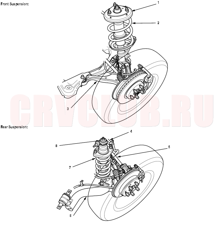
Component Location Index18-3
Disposal, page 18-11 ; Replacement, page 18-21 Replacement, page 18-21 Replacement, page 18-20 Replacement, page 18-32 Replacement, page 18-34 Replacement, page 18-35 Replacement, page 18-36 Disposal, page 18-11 ; Replacement, page 18-36
Wheel Alignment18-4
Special Tool Required
Wheel alignment gauge attachment 07MGK-0010100
The suspension can be adjusted for front camber, front toe, and rear toe. However, each of these adjustments are interrelated to each other. For example, when you adjust toe, the camber changes. Therefore, you must adjust the front wheel alignment whenever you adjust camber or toe.
Pre-Alignment Checks
For proper inspection and adjustment of the wheel alignment, do these checks:
- Release the parking brake to avoid an incorrect measurement.
- Make sure the suspension is not modified.
- Check the tire size and tire pressure.
Tire size:
Front/rear:
15 inch wheel disc: 205/70R15 96T
16 inch wheel disc: 205/65R16 95T
Tire pressure:
Front/rear:
180 kPa (1.8 kgf/cm², 26 psi)
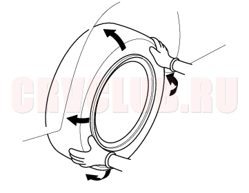
- Check the runout of the wheels and tires.
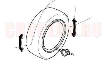
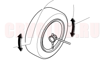
- Check the suspension ball joints. (Hold a wheel with your hands, and move it up and down and right and left to check for wobbling).
- Bounce the vehicle up and down several times to stabilize the suspension.
Front Caster Inspection
- Raise the vehicle and set the turning radius gauges beneath the front wheels, and place boards under the rear wheels the same thickness as the turning radius gauges, then lower the vehicle.
- NOTE: Be sure that the vehicle is level with the wheels on the turning radius gauges and boards.
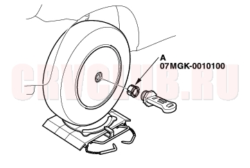
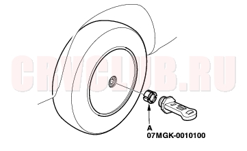
- Remove the wheel cap, and install the wheel alignment gauge attachment (A) and camber/caster gauge on the wheel hub, and apply the front brake.
- Turn the front wheel 20° outward, then turn the adjusting screw of the camber/caster gauge to set the bubble at 0°.
- Turn the wheel 20° inward and read the caster on the gauge with the bubble at the center of the gauge. If the caster angle is not within the specification, check for bent or damaged suspension components.
Front Caster angle: 1°45' ± 1°
18-5
Front Camber Inspection
- Turn the front wheels to the straight ahead position.
- Remove the wheel cap, and install the wheel alignment gauge attachment (A) and camber/caster gauge on the wheel hub.
- Read the camber angle on the gauge with the bubble at the center of the gauge. If the camber angle is not within the specification, adjust the camber (see the right column).
Front camber angle: 0°00' ± 45'
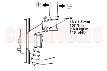
Front Camber Adjustment
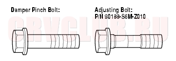
The front camber can be adjusted by exchanging one or both of the damper pinch bolts with the smaller diameter adjusting bolt(s). The difference between the adjusting bolt diameter and the pinch bolt hole diameter allows a small range of adjustment.
- Raise the front of the vehicle, and make sure it is securely supported. Remove the front wheels.
- Loosen the damper pinch nuts and bolts (A), and adjust the camber by moving the bottom of the damper within the range of the damper pinch bolt free play.
- Tighten the nuts to the specified torque. Make sure the damper pinch bolts tightening torque.
- Reinstall the front wheels. Lower the front of the vehicle to the ground, and bounce the vehicle several times to stabilize the suspension.
- Check the camber angle. If it is within the specification, check the front toe. If it is not within the specification, go to step 6.
Wheel Alignment (cont'd)18-6
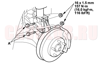
- Raise the front of the vehicle, and make sure it is securely supported. Remove the front wheels.
- Replace the damper pinch bolts with the adjusting bolts (A), and adjust the camber angle.
- NOTE: The camber angle can be adjusted up to ± 15' (center of tolerance) by replacing one damper pinch bolt with the adjusting bolt. The camber angle can be adjusted up to ± 30' by replacing both upper and lower damper pinch bolts with the adjusting bolts.
- Tighten the bolts to the specified torque.
- Reinstall the front wheels. Lower the front of the vehicle to the ground, and bounce the vehicle several times to stabilize the suspension.
- Check the camber angle. If it is within the specification, check the front toe, and adjust it if necessary. If it is not within the specification, readjust it, and recheck. If the camber angle cannot be adjusted to the specification, check for bent or damaged suspension components.
Rear Camber Inspection
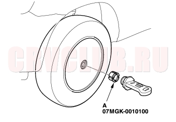
- Remove the wheel cap, and install the wheel alignment gauge attachment (A) and camber/caster gauge on the wheel hub.
- Read the camber angle on the gauge with the bubble at the center of the gauge. If the camber angle is not within the specification, check for bent or damaged suspension components.
Rear camber angle: - 0°45' ± 45'
NOTICE
Do not loosen the special bolts on the trailing arm. 18-7
Front Toe Inspection/Adjustment
- Center the steering wheel spokes.
- Check the toe. If it is not within the specification, go to step 3.
Front toe-in: 0 ± 2 mm (0 ± 0.08 in.)
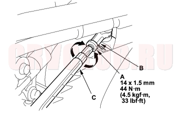
- Loosen the locknut (A) while holding the tie-rod end (B).
- Turn the tie-rod end (C) until the toe is correct.
- NOTE: Adjust both the right and left wheels at the same time by the same amount in opposite directions to obtain the correct toe and to keep the steering wheel straight.
- After adjusting, tighten the locknut while holding the tie-rod arm. Make sure the toe setting does not change.
Rear Toe Inspection/Adjustment
Rear toe-in: 2 ± 2 mm (0 ± 0.08 in.)
NOTICE
Do not loosen the special bolts (C) on the trailing arm.
- Replace the self-locking nut with a new one, and lightly tighten it.
- NOTE: Always use a new self-locking nut whenever it has been loosened.
- Turn the adjusting bolt until the toe is correct.
Rear toe-in:
0 (from -1 to +2) mm (0 (from -0.04 to +0.08) in.)
Wheel Alignment (cont'd)18-8
Turning Angle Inspection
- Raise the vehicle and set the turning radius gauges beneath the front wheels, and place boards under the rear wheels the same thickness as the turning radius gauges, then lower the vehicle.
- NOTE: Be sure that the vehicle is level with the wheels on the turning radius gauges and boards.
- Turn the steering wheel fully to the right and left while applying the brakes, and check the turning angles of both front wheels. If the turning angle is not within the specification or the inward turning angles differ between the right and left, go to step 3.
Turning angle:
Inward: 39°45' ± 2°
Outward: 32°30' (reference)
- Check the toe. If it is correct but the turning angle is not within the specification, check for bent or damaged suspension components.
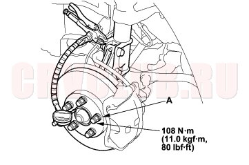
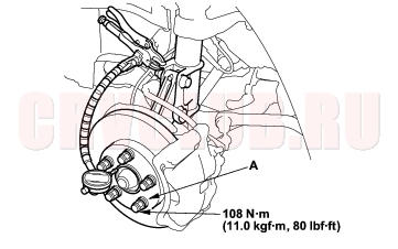
Wheel Bearing End Play Inspection18-8
- Raise the vehicle, and make sure it is securely supported. Remove the wheels.
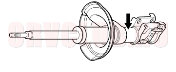
- Install suitable flat washers (A) and wheel nuts, and tighten the nuts to the specified torque to hold the brake disc securely against the hub.
- Set up the dial gauge against the hub cap or hub flange as shown, and measure the bearing end play by moving the brake disc inward and outward.
Bearing end play:
Standard:
Front/rear: 0 - 0.05 mm (0 - 0.002 in.)
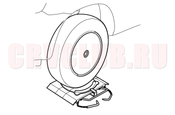
Wheel Runout Inspection18-9
- Raise the vehicle, and make sure it is securely supported.
- Check for a bent or deformed wheel.
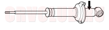
- Set up the dial gauge as shown, and measure the axial runout by turning the wheel.
Front and rear wheel axial runout:
Standard:
Aluminum wheel: 0 - 0.7 mm (0 - 0.03 in.)
Steel wheel: 0 - 1.0 mm (0 - 0.04 in.)
Service limit: 2.0 mm (0.08 in.)
Front and rear wheel radial runout:
Standard:
Aluminum wheel: 0 - 0.7 mm (0 - 0.03 in.)
Steel wheel: 0 - 1.0 mm (0 - 0.04 in.)
Service limit: 1.5 mm (0.06 in.)
- If the wheel runout is not within the specification, check the wheel bearing end play (see page 18-8) , and make sure the mating surfaces on the brake disc and the inside of the wheel are clean.
- If the bearing end play is within the specification but the wheel runout is more than the service limit, replace the wheel.
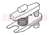
Ball Joint Removal18-10
Special Tools Required
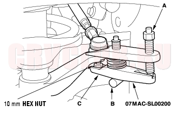
Ball joint remover, 28 mm 07MAC-SL00200
NOTICE
Always use a ball joint remover to disconnect a ball joint. Do not strike the housing or any other part of the ball joint connection to disconnect it.
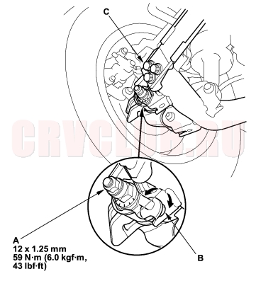
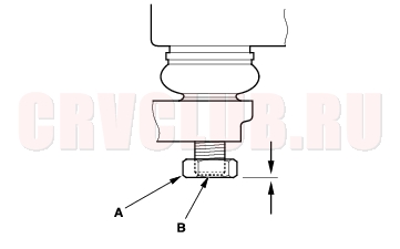
- Install a hex nut (A) onto the threads of the ball joint (B). Make sure the nut is flush with the ball joint pin end to prevent damage to the thread end of the ball joint pin.
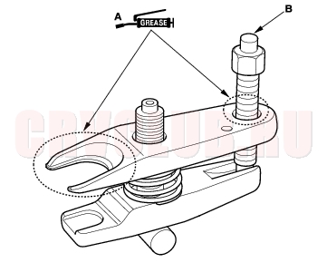
- Apply grease to the special tool on the areas shown (A). This will ease installation of the tool and prevent damage to the pressure bolt (B) threads.
- Install the special tool as shown. Insert the jaws carefully, making sure not to damage the ball joint boot. Adjust the jaw spacing by turning the pressure bolt (A).
- After adjusting the adjusting bolt, make sure the head of the adjusting bolt (B) is in the position shown to allow the jaw (C) to pivot.
- With a wrench, tighten the pressure bolt until the ball joint pin pops loose from the steering arm or knuckle. If necessary, apply penetrating type lubricant to loosen the ball joint pin.
- NOTE: Do not use pneumatic or electric tools on the pressure bolt.
- Remove the tool, then remove the nut from the end of the ball joint pin, and pull the ball joint out of the steering arm or knuckle. Inspect the ball joint boot, and replace it if damaged.
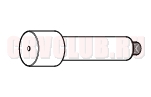
Damper Disposal18-11
The dampers contain nitrogen gas and oil under pressure. The pressure must be relieved before disposal to prevent explosion and possible injury when scrapping.
Always wear eye protection to avoid getting metal shavings in your eyes when the damper pressure is relieved.
Place the damper on a level surface with its shaft extended and drill a hole of 2 - 3 mm (0.078 - 0.118 in.) diameter in the body to release the gas.
|
Suspension18-1
Front and Rear Suspension18-2 |