Front Suspension18-12
|
Suspension18-1
Front Suspension18-12 |
Front Suspension18-12
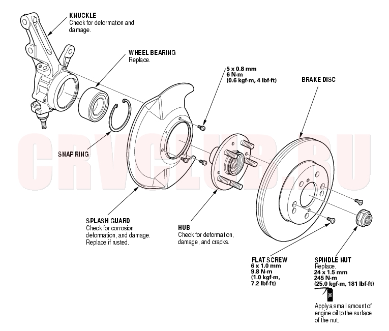
Knuckle/Hub/Wheel Bearing Replacement
Exploded View
18-13
Special Tools Required
Hub dis/assembly tool 07GAF-SD40100 Ball joint remover, 28 mm 07MAC-SL00200 Attachment 62 x 68 mm 07746-0010500 Driver 07749-0010000 Support base 07965-SD90100 Knuckle/Hub Replacement
- Raise the front of the vehicle, and make sure it is securely supported.
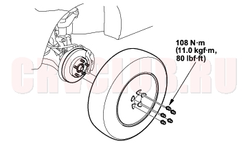
- Remove the wheel cap, wheel nuts, and front wheel.
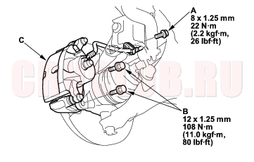
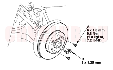
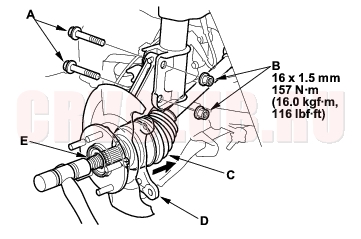
- Remove the brake hose bracket mounting bolt (A).
- Remove the caliper bracket mounting bolts (B), and remove the caliper assembly (C) from the knuckle. To prevent damage to the caliper assembly or brake hose, use a short piece of wire to hang the caliper assembly from the undercarriage. Do not twist the brake hose with force.
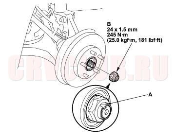
- Raise the stake (A), and remove the spindle nut (B).
- Remove the brake disc retaining flat screws (A).
- Screw two 8 × 1.25 mm bolts (B) into the disc to push it away from the hub. Turn each bolt two turns at a time to prevent cocking the disc excessively.
Knuckle/Hub/Wheel Bearing Replacement (cont'd)18-14
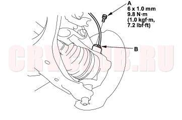
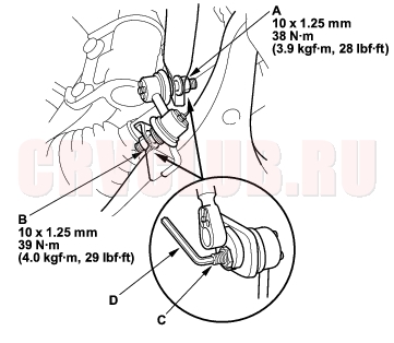
- Remove the flange bolt (A) and wheel sensor (B) from the knuckle. Do not disconnect the wheel sensor connector.
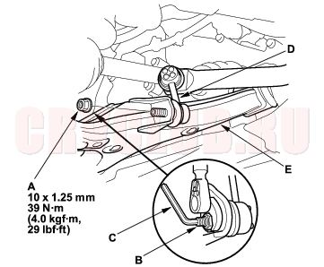
- Remove the flange nut (A) while holding the joint pin (B) with a hex wrench (C), and disconnect the stabilizer link (D) from the lower arm (E).
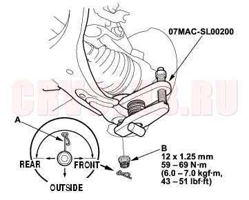
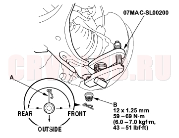
- Remove the clip (A) from the lower arm ball joint, and remove the castle nut (B).
- NOTE: During installation, insert the clip into the ball joint pin from the inside to the outside of the vehicle. The closed end of the clip must be in the range shown.
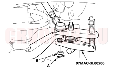
- Disconnect the lower arm from the knuckle using the special tool (see page 18-10) .
- Loosen the damper pinch bolts (A) while holding the nuts (B), and remove the bolts and nuts.
- Remove the driveshaft outboard joint (C) from the knuckle (D) by tapping the driveshaft end (E) with a plastic hammer while drawing the knuckle outward, then remove the knuckle.
- NOTE: Do not pull the driveshaft end outward. The driveshaft joint may come off.
18-15
- Install the knuckle/hub/in the reverse order of removal, and note these items:
- Be careful not to damage the ball joint boot when installing the knuckle.
- Tighten all mounting hardware to the specified torque values.
- First install all the components and lightly tighten the bolts and nuts, then raise the suspension to load it with the vehicle's weight before fully tightening to the specified torques. Do not place the jack against the ball joint pin of the lower arm.
- Torque the castle nut to the lower torque specification, then tighten it only far enough to align the slot with the clip hole. Do not align the castle nut by loosening it.
- Install a new clip on the castle nut after torquing.
- Use a new spindle nut on reassembly.
- Before installing the spindle nut, apply a small amount of engine oil to the seating surface of the nut. After tightening, use a drift to stake the spindle nut shoulder against the driveshaft.
- Replace the self-locking nuts, damper pinch bolts and nuts with new ones.
- Before installing the brake disc, clean the mating surface of the front hub and the inside of the brake disc.
- Before installing the wheel, clean the mating surface of the brake disc and the inside of the wheel.
- Check the front wheel alignment, and adjust it if necessary (see page 18-4) .
Wheel Bearing Replacement
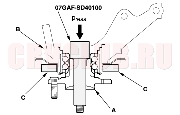
- Separate the hub (A) from the knuckle (B) using the special tool and a hydraulic press. Hold the knuckle with the attachment (C) of the hydraulic press or equivalent tool. Be careful not to deform the splash guard. Hold onto the hub to keep it from falling when pressed clear.
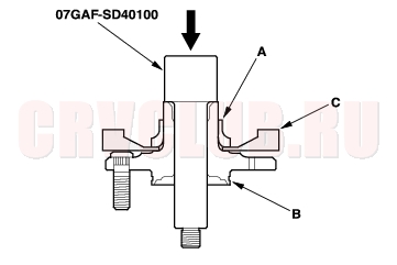
- Press the wheel bearing inner race (A) off of the hub (B) using the special tool, a commercially available bearing separator (C), and a press.
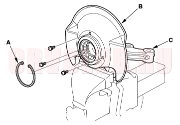
- Remove the snap ring (A) and the splash guard (B) from the knuckle (C).
Knuckle/Hub/Wheel Bearing Replacement (cont'd)18-16
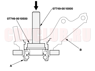
- Press the wheel bearing (A) out of the knuckle (B) using the special tool and a press.
- Wash the knuckle and hub thoroughly in high flash point solvent before reassembly.
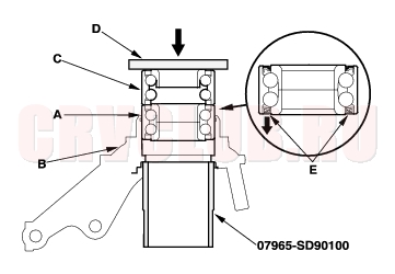
- Press a new wheel bearing (A) into the knuckle (B) using the old bearing (C), a steel plate (D), the special tool, and a press.
- NOTE:
- Install the wheel bearing with the magnetic encoder (E) (brown color), toward the inside of the knuckle.
- Remove any oil, grease, dust and other foreign material from the encoder surface.
- Keep any magnetic tools away from the encoder surface.
- Be careful not to damage the encoder surface when you insert wheel bearing.
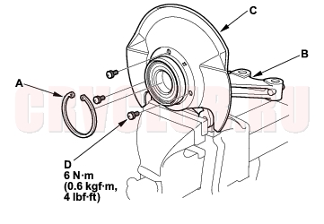
- Install the snap ring (A) securely in the knuckle (B).
- Install the splash guard (C), and tighten the screws (D) to the specified torque.
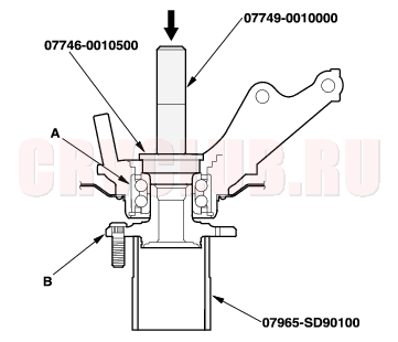
- Press a wheel bearing (A) onto the hub (B) using the special tools and a press.
Ball Joint Boot Replacement18-17
Special Tools Required
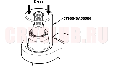
Front hub dis/assembly tool 07965-SA50500
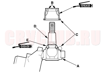
- Remove the boot. Check for a gap (A) between the ball joint and the knuckle. If there is a gap, replace the knuckle assembly. Do not press the ball joint back into the knuckle.
- Pack the interior and lip (B) of a new boot with fresh grease. Keep the grease off of the boot-to-knuckle mating surfaces (C).
- Wipe the grease off the tapered section of the pin (D), and pack fresh grease onto the base (E).
- Install the boot onto the ball joint pin, then squeeze it gently to force out any air. Do not let dirt or other foreign materials get into the boot.
- Press the boot with the special tool until the bottom seats on the knuckle (A) evenly around.
- After installing a boot, wipe any grease off the exposed portion of the ball joint pin.
Stabilizer Link Replacement18-18
- Raise the front of the vehicle, and make sure it is securely supported. Remove the front wheels.
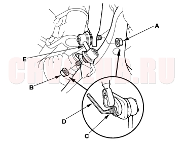
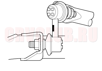
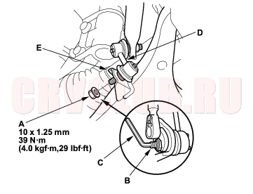
- Remove the self-locking nut (A) and flange nut (B) while holding the respective joint pin (C) with a hex wrench (D), and remove the stabilizer link (E).
- Install the stabilizer link on the stabilizer bar and lower arm with the joint pins set at the center of each moving range.
- Install the self-locking nut and flange nut, and lightly tighten them.
- NOTE: Use a new self-locking nut on reassembly.
- Place the floor jack under the lower arm ball joint, and raise the suspension to load it with the vehicle's weight.
NOTICE
Do not place the jack against the ball joint pin of the lower arm.
- Tighten the new self-locking nut (A) and flange nut (B) to the specified torque values while holding the respective joint pins (C) with a hex wrench (D).
- After 5 minutes of driving, re-tighten the self-locking nut again to the specified torque.
Stabilizer Bar Replacement18-19
- Raise the front of the vehicle, and make sure it is securely supported. Remove the front wheels.
- Disconnect the stabilizer links from the stabilizer bar on the right and left (see page 18-18) .
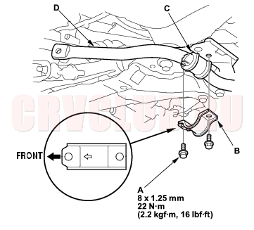
- Remove the flange bolts (A) and bushing holders (B), then remove the bushings (C) and the stabilizer bar (D).
- Install the stabilizer bar in the reverse order of removal, and note these items:
- Use new self-locking nuts on reassembly.
- Note the right and left direction of the stabilizer bar.
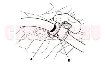
- Align the ends of the paint marks (A) on the stabilizer bar with each end of the bushings (B).
- Note the fore/aft direction of the bushing holders.
- Refer to Stabilizer Link Replacement to connect the stabilizer bar to the links (see page 18-18) .
Lower Arm Replacement18-20
Special Tools Required
Ball joint remover, 28 mm 07MAC-SL00200
- Raise the front of the vehicle, and make sure it is securely supported. Remove the front wheels.
- Remove the flange nut (A) while holding the joint pin (B) with a hex wrench (C), and disconnect the stabilizer link (D) from the lower arm (E).
- Remove the clip (A) from the lower arm ball joint, and remove the castle nut (B).
- NOTE: During installation, insert the clip into the ball joint pin from the inside to the outside of the vehicle. The closed end of the clip must be in the range shown.
- Disconnect the lower arm from the knuckle using the special tool (see page 18-10) .
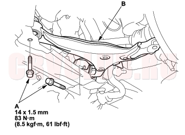
- Remove the flange bolts (A), and remove the lower arm (B).
- Install the lower arm in the reverse order of removal, and note these items:
- Be careful not to damage the ball joint boot when connecting the lower arm to the knuckle.
- Tighten all mounting hardware to the specified torque values.
- First install all the components and lightly tighten the bolts and nuts, then raise the suspension to load it with the vehicle's weight before fully tightening it to the specified torques. Do not place the jack on the lower arm ball joint.
- Torque the castle nut to the lower torque specification, then tighten it only far enough to align the slot with the clip hole. Do not align the castle nut by loosening it.
- Install a new clip on the castle nut after torquing.
- Before installing the wheel, clean the mating surface of the brake disc and the inside of the wheel.
- Check the wheel alignment, and adjust it if necessary (see page 18-4) .
Damper/Spring Replacement18-21
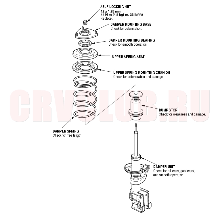
Exploded View
Damper/Spring Replacement (cont'd)18-22
Special Tools Required
Ball joint remover, 28 mm 07MAC-SL00200
Removal
- Raise the front of the vehicle, and make sure it is securly supported. Remove the front wheels.
- Remove the cotter pin (A) from the tie-rod end ball joint, and remove the nut (B).
- Disconnect the tie-rod end from the steering arm on the damper using the special tool (see page 18-10) .
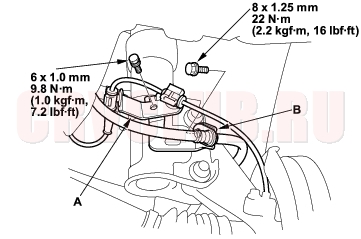
- Remove the bolts, and remove the wheel sensor harness bracket (A) and brake hose bracket (B) from the damper. Do not disconnect the wheel sensor connector.
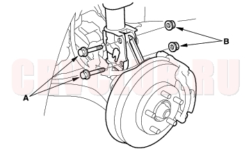
- Remove the damper pinch bolts (A) while holding the nuts (B).
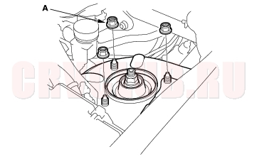
- Remove the flange nuts (A) from the top of the damper.
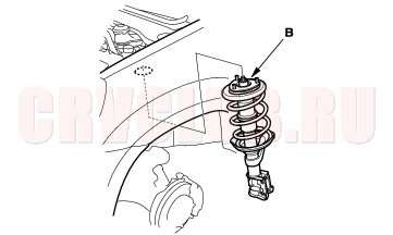
- Lower the lower arm, and remove the damper assembly (B).
18-23
Disassembly/Inspection
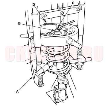
- Compress the damper spring with the commercially available strut compressor (A) according to the manufacturer's instructions, then remove the self-locking nut (B) while holding the damper shaft (C) with a hex wrench (D). Do not compress the spring more than necessary to remove the nut.
- Release the pressure from the strut spring compressor, then disassemble the damper as shown in the Exploded View.
- Reassemble all the parts, except for the apper spring seat and spring.
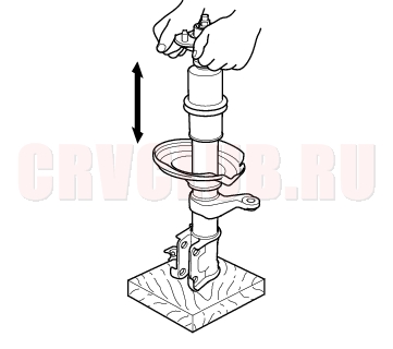
- Compress the damper assembly by hand, and check for smooth operation through a full stroke, both compression and extension. The damper should extend smoothly and constantly when compression is released. If it does not, the gas is leaking and the damper should be replaced.
- Check for oil leaks, abnormal noises, and binding during these tests.
Damper/Spring Replacement (cont'd)18-24
Reassembly
NOTE: Refer to the Exploded View as needed.
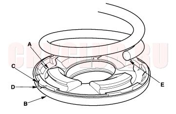
- Install the upper spring mounting cushion (A) on the upper spring seat (B) by aligning the log portion (C) on cushion with cutout (D) in the seat.
- Install the spring (E) in the groove of the cushion securely fitted.
- Install the damper mounting bearing and damper mounting base on the upper spring seat.
- Install the upper spring seat and the spring on a commercially available strut spring compressor (A), and compress the spring lightly.
- Insert the damper unit (B) up through the compressed spring.
- Align the bottom of the spring (C) and the stepped part (D) of the lower spring seat.
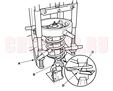
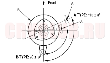
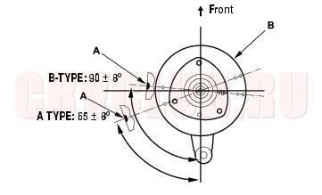
- Check that the cutout (A) in the side of the upper spring seat (B) is in position shown. Note that there are two types of the damper, A type and B type, and the cutout position is different from type to type.
A type damper: P/N 51601/51602-S9A-G02
B type damper: P/N 51601/51602-S9A-G12
The part No. is shown on the damper unit label. If the cutout is out of position, repeat to the step 1 and reassemble the spring and upper spring seat accordingly.
18-25
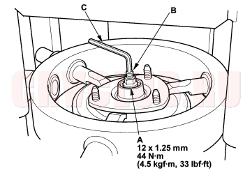
- Hold the bottom of the damper with your hand, and compress the spring. Do not compress the spring excessively.
- Install the 12 mm nut (A) on the damper shaft (B). Hold the damper shaft with a hex wrench (C), and tighten the 12 mm nut to the specified torque.
- Remove the damper assembly from the strut spring compressor.
Installation
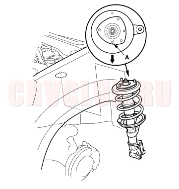
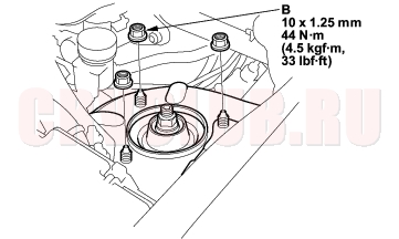
- Lower the lower arm, and position the damper assembly in the body. Turn the damper mounting base so that the ''
L'' mark (A) faces toward the outside of the vehicle.
- Loosely install flange nuts (B) onto the top of the damper.
Damper/Spring Replacement (cont'd)18-26
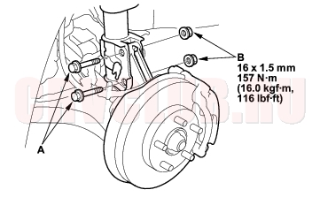
- Position the damper on the knuckle, and install the new damper pinch bolts (A) and nuts (B), and lightly tighten the nuts.
- Place the floor jack under the lower arm ball joint, and raise the suspension to load it with the vehicle's weight.
NOTICE
Do not place the jack against the lower arm ball joint.
- Tighten the flange nuts on the top of the damper to the specified torque.
- Tighten the damper pinch nuts to the specified torque.
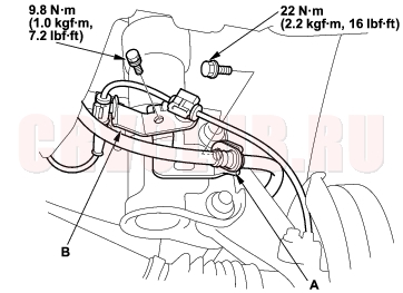
- Install the brake hose bracket (A) and the wheel sensor harness bracket (B) onto the damper, and tighten the bolt to the specified torque.
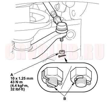
- Connect the tie-rod end to the steering arm, and tighten the nut (A) to the specified torque. Install the cotter pin (B) after tightening, and bend its end as shown.
- Clean the mating surface of the brake disc and the inside of the wheel, then install the front wheels.
- Check the wheel alignment, and adjust it if necessary (see page 18-4) .
|
Suspension18-1
Front Suspension18-12 |