Rear Suspension18-27
|
Suspension18-1
Rear Suspension18-27 |
Rear Suspension18-27
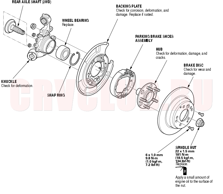
Knuckle/Hub/Wheel Bearing Replacement
Exploded View
Knuckle/Hub/Wheel Bearing Replacement (cont'd)18-28
Special Tools Required
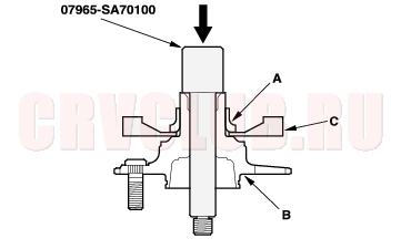
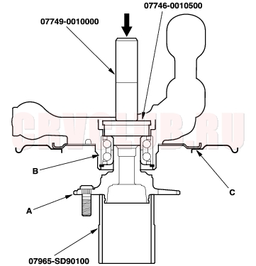
Hub dis/assembly tool 34 mm 07965-SA70100 Ball joint remover, 28 mm 07MAC-SL00200 Attachment 62 × 68 mm 07746-0010500 Driver 07749-0010000 Support base 07965-SD90100 Knuckle Replacement
- Raise the rear of the vehicle, and make sure it is securely supported. Remove the rear wheels.
- Release the parking brake lever.
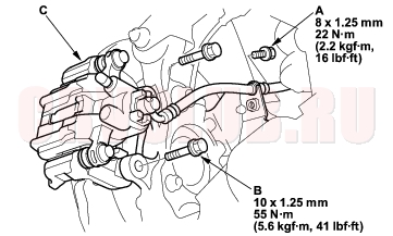
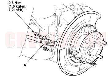
- Remove the brake hose mounting bolt (A).
- Remove the caliper bracket mounting bolts (B), and hang the caliper (C) to one side. To prevent damage to the caliper or brake hose, use a short piece of wire to hang the caliper from the undercarriage.
- Remove the brake disc retaining screw (A), screw two 8 × 1.25 mm bolts into the brake disc/drum (B) to push it away from the hub. Turn each bolt two turns at a time to prevent cocking the brake disc/drum excessively. Remove the brake disc/drum.
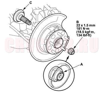
- Raise the stake (A), and remove the spindle nut (B) and rear axle shaft (vehicles with 2WD) (C).
18-29
- Remove the parking brake shoes (see page 19A-36) .
- Remove the parking brake cable (A) from the backing plate.
- NOTE: The parking brake cable must not be bent or distorted. This will lead to stiff operation and premature cable failure.
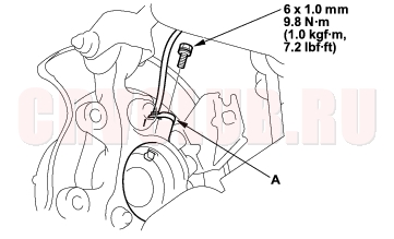
- Remove the wheel sensor (A) from the knucke (if equipped with ABS).
- Place a floor jack under the trailing arm (A) to support it.
- NOTE: Do not place the jack against the plate section of the lower arm. Be careful not to damage any suspension components.
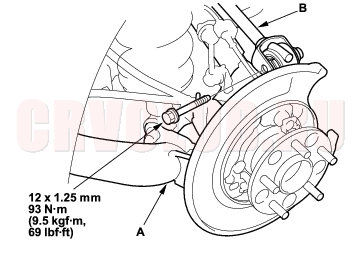
- Remove the flange bolt, and disconnect the upper arm (B) from the knuckle.
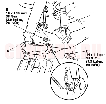
- Mark the cam positions of the adjusting bolt (A) and adjusting cam (B), then remove the self-locking nut (C), adjusting cam, and adjusting bolt. Discard the self-locking nut.
Knuckle/Hub/Wheel Bearing Replacement (cont'd)18-30
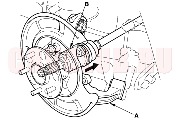
- Remove the knuckle (A) while pushing in the driveshaft and holding the driveshaft outboard joint (B). (4WD only)
- Install the knuckle in the reverse order of removal, and note these items:
- First install all the suspension components, and lightly tighten the bolts and nuts, then place a floor jack under the lower arm, and raise the suspension to load it with the vehicle's weight before fully tightening the bolts and nuts to the specified torque values.
- Align the cam positions of the adjusting bolt (A) and adjusting cam (B) with the marked positions when tightening.
- Use a new self-locking nut on reassembly.
- Use a new spindle nut on reassembly.
- Before installing the spindle nut, apply a small amount of engine oil to the seating surface of the nut. After tightening, use a drift to stake the spindle nut shoulder against the driveshaft.
- Before installing the brake disc/drum,clean the mating surfaces of the rear hub and the inside of the brake disc/drum.
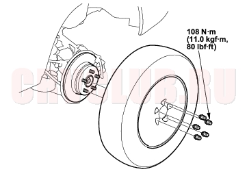
- Before installing the wheel, clean the mating surfaces of the brake disc/drum and the inside of the wheel.
- Check the rear wheel alignment, and adjust it if necessary (see page 18-4) .
Wheel Bearing Replacement
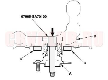
- Separate the hub (A) from the knuckle (B) using the special tool and a hydraulic press. Hold the knuckle with a press attachment (C) or equivalent tool. Be careful not to deform the splash guard. Hold onto the hub to keep it from falling when pressed clear.
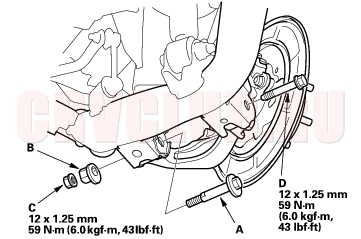
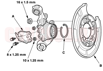
- Remove the brake hose mounting bracket (A).
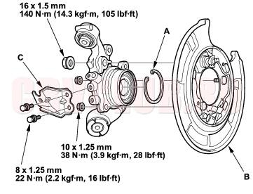
- Remove the backing plate (B), and snap ring (C).
18-31
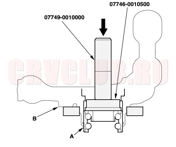
- Press the wheel bearing (A) out of the knuckle (B) using the special tools and a press.
- Press the wheel bearing inner race (A) from the hub (B) using the special tool, a commercially available bearing separator (C), and a press.
- Wash the knuckle and hub thoroughly in high flesh point solvent before reassembly.
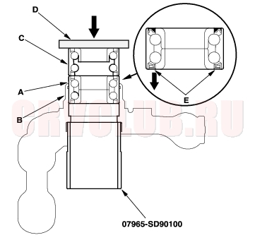
- Press a new wheel bearing (A) into the knuckle (B) using the old bearing (C), a steel plate (D), the special tool, and a press. Be careful not to damage the sleeve of the pack seal.
- NOTE:
- Install the wheel bearing with the magnetic encorder (E) (brown color), toward the inside of the knuckle.
- Remove any oil, grease, dust and other foreign material from the encoder surface.
- Keep any magnetic tools away from the encoder surface.
- Be careful not to damage the encoder surface when you insert wheel bearing.
Knuckle/Hub/Wheel Bearing Replacement (cont'd)18-32
- Install the snap ring (A), backing plate (B), and brake hose mounting bracket (C). Tighten the flange nuts and bolts to the specified torque.
- Install the hub (A) on the knuckle (B) using the special tools and a hydraulic press. Be careful not to deform the backing plate (C).
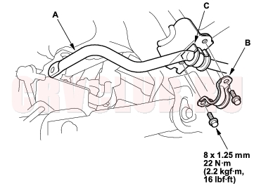
Stabilizer Bar Replacement18-32
- Raise the rear of the vehicle, and make sure it is securely supported. Remove the rear wheels.
- Disconnect the stabilizer links from the stabilizer bar (A) on the right and left (see page 18-33) .
- Remove the flange bolts and bushing holders (B), then remove the bushings (C) and the stabilizer bar.
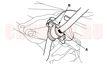
- Install the stabilizer bar in the reverse order of removal, and note these items:
- Use new self-locking nuts on reassembly.
- Make sure the right and left ends of the stabilizer bar are installed on their respective sides of the vehicle.
- Align the ends of the paint marks (A) on the stabilizer bar with the bushings (B).
- Refer to Stabilizer Link Replacement to connect the stabilizer bar to the links (see page 18-33) .
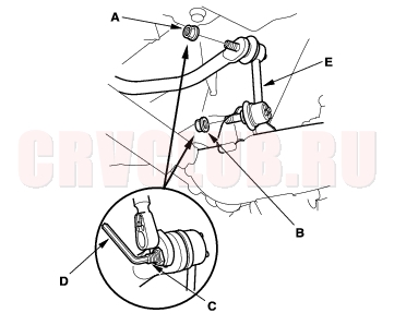
Stabilizer Link Replacement18-33
- Raise the rear of the vehicle, and make sure it is securely supported. Remove the rear wheels.
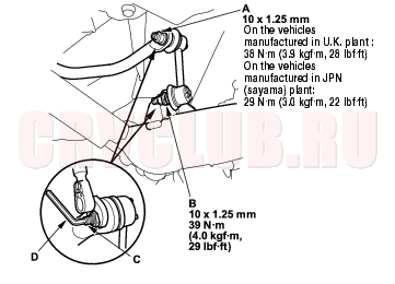
- Remove the self-locking nut (A) and flange nut (B) while holding the respective joint pin (C) with a hex wrench (D), and remove the stabilizer link (E).
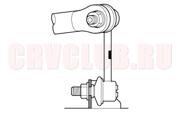
- Install the stabilizer link on the stabilizer bar and trailing arm with the joint pins set at the center of each moving range.
- Install the self-locking nut and flange nut, and lightly tighten them.
- NOTE: Use a new self-locking nut on reassembly.
- Place a jack under the trailing arm at the knuckle side end, and raise the suspension to load it with the vehicle's weight.
- Tighten the new self-locking nut (A) and flange nut (B) to the specified torque values while holding the respective joint pins (C) with a hex wrench (D).
- After 5 minutes of driving, re-tighten the self-locking nut again to the specified torque.
Upper Arm Replacement18-34
- Raise the rear of the vehicle, and make sure it is securely supported. Remove the rear wheels.
- Place a floor jack under the trailing arm, and support the suspension.
- Remove the wheel sensor harness bracket (A) from the upper arm (B).
- Remove the flange bolts (A), and remove the upper arm (B).
- Install the upper arm in the reverse order of removal, and note these items:
- First install all the suspension components and lightly tighten the bolts and nuts, then place a jack under the trailing arm, and raise the suspension to load it with the vehicle's weight before fully tightening the bolts and nuts to the specified torque values.
- Tighten all the mounting hardware to the specified torque values.
- Before installing the wheel, clean the mating surface of the brake disc and the inside of the wheel.
- Check the wheel alignment, and adjust it if necessary (see page 18-4) .
Trailing Arm Replacement18-35
- Raise the rear of the vehicle, and make sure it is securely supported. Remove the rear wheels.
- Remove the knuckle (see page 18-28) .
- Place the floor jack under the trailing arm (A) to support it.
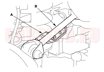
- Remove the flange nut (B), and disconnect the stabilizer link (C) from the trailing arm.
- Remove the flange bolt (D), and disconnect the damper (E) from the trailing arm.
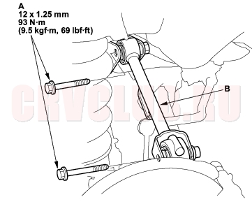
- Remove the trailing arm front mounting bolts (A).
- Remove the trailing arm rear mounting bolt (A).
NOTICE
Do not loosen the special bolts (B) on the trailing arm.
- Lower the jack, and remove the trailing arm.
- Install the trailing arm in the reverse order of removal, and note these items:
- First install all the suspension components and lightly tighten the bolts and nuts, then place a jack under the trailing arm, and raise the suspension to load it with the vehicle's weight before fully tightening the bolts and nuts to the specified torque values.
- Tighten all the mounting hardware to the specified torque values.
- Before installing the wheel, clean the mating surface of the brake disc and the inside of the wheel.
- Check the wheel alignment, and adjust it if necessary (see page 18-4) .
Damper/Spring Replacement18-36
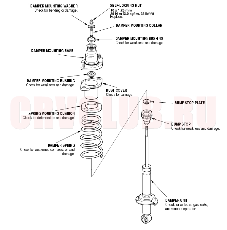
Exploded View
18-37
Removal
- Raise the rear of the vehicle, and make sure it is securely supported. Remove the rear wheels.
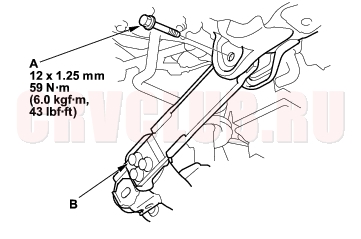
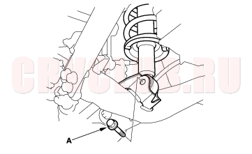
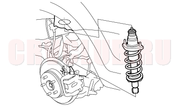
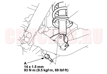
- Remove the flange bolt (A) from the bottom of the damper.
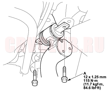
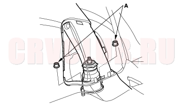
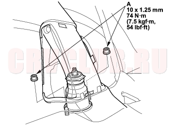
- Remove the flange nuts (A) from the top of the damper in the cargo area.
- Remove the damper assembly from the body.
Damper/Spring Replacement (cont'd)18-38
Disassembly/Inspection
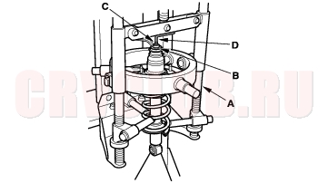
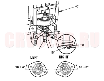
- Compress the damper spring with the commercially available strut compressor (A) according to the manufacturer's instructions, then remove the self-locking nut (B) while holding the damper shaft (C) with a hex wrench (D). Do not compress the spring more than necessary to remove the nut.
- Release the pressure from the strut spring compressor, then disassemble the damper as shown in the Exploded View.
- Reassemble all the parts, except for the spring.
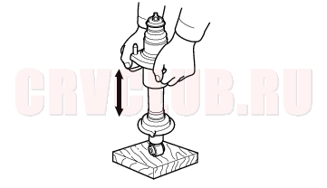
- Compress the damper assembly by hand, and check for smooth operation through a full stroke, both compression and extension. The damper should extend smoothly and constantly when compression is released. If it does not, the gas is leaking and the damper should be replaced.
- Check for oil leaks, abnormal noises, or binding during these tests.
Reassembly
- Install all the parts except the damper mounting washer and self-locking nut onto the damper unit by referring to the Exploded View. Align the bottom of the spring (A) and the stepped part of the lower spring seat (B), and align the damper mounting base as shown.
- Install the damper assembly on a commercially available strut spring compressor (C).
- Compress the damper spring with the spring compressor.
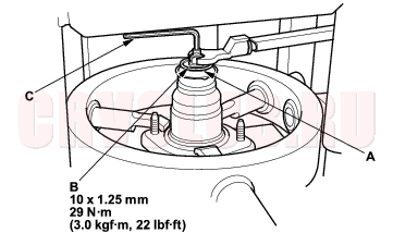
- Install the washer (A) and a new self-locking nut (B) on the damper shaft.
- Hold the damper shaft with a hex wrench (C), and tighten the self-locking nut to the specified torque.
18-39
Installation
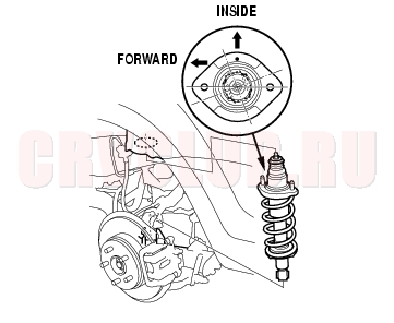
- Position the damper assembly in the body. Note the direction of the damper mounting base so that the small hole dot on it is toward the inside of the vehicle.
- Loosely install the flange nuts (A) onto the top of the damper.
- Loosely install the flange bolt (A) on the bottom of the damper.
- Raise the suspension with a floor jack to load the vehicle weight, and tighten the nuts and bolt to the specified torque values.
- Clean the mating surface of the brake disc and the inside of the wheel, then install the rear wheel.
- Check the wheel alignment, and adjust it if necessary (see page 18-4) .
|
Suspension18-1
Rear Suspension18-27 |