M/T Differential13-56
|
M/T - M/T Differential13-1
M/T Differential13-56 |
M/T Differential13-56
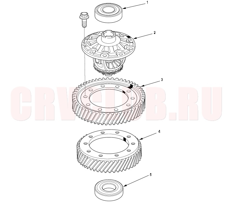
Component Location Index
4WD model
Replacement, page 13-59 Backlash Inspection, page 13-58 ; Replacement, page 13-58 Replacement, page 13-58 Replacement, page 13-58 Replacement, page 13-59
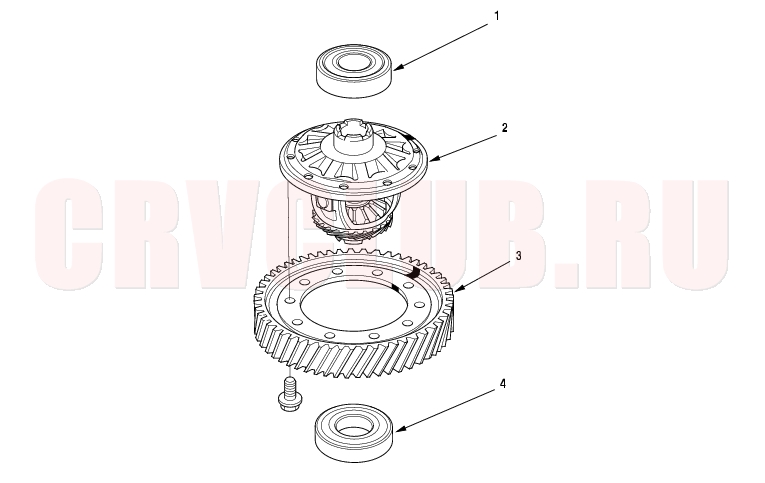
2WD model
Replacement, page 13-59 Backlash Inspection, page 13-58 ; Replacement, page 13-58 Replacement, page 13-58 Replacement, page 13-59
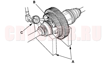
Backlash Inspection13-58
NOTE: 4WD model is shown, 2WD model is similar.
- Place the differential assembly on V-blocks (A), and install both axles.
- Measure the backlash of both pinion gears (B) with a dial indicator (C). If the backlash is not within the standard, replace the differential carrier.
Standard (New): 0.05 - 0.15 mm (0.002 - 0.006 in.)
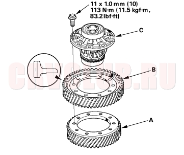
Driven Gear/Carrier Replacement13-58
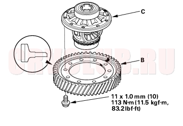
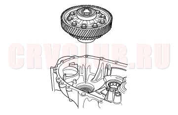
- Remove the bolts (left-hand threads) in a crisscross pattern in several steps, then remove the transfer driven gear (A), final driven gear (B) from the differential carrier(C).
- NOTE: Align the mark of driven gear and the carrier.
4WD model:
2WD model:
- Install the final driven gear with the chamfer on the inside diameter facing the carrier. Tighten the bolts in a crisscross pattern in several steps.
Carrier Bearings Replacement13-59
Special Tool Required
Driver, 40 mm I.D. 07746-0030100
NOTE: 4WD model is shown, 2WD model is similar.
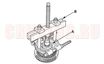
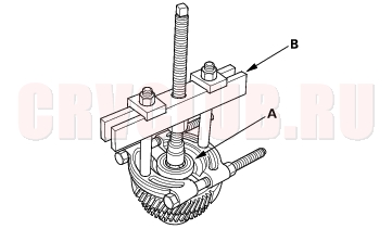
- Check the carrier bearings for wear and rough rotation. If they rotate smoothly and their rollers show no signs of wear, the beaings are OK.
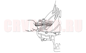
- Remove the carrier bearing (A) with a commercially-available bearing puller (B).
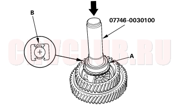
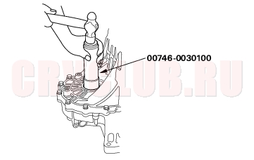
- Install the new bearings (A) with the special tool and a press. Press each bearing on until it bottoms. There should be no clearance between the bearings and the carrier.
- NOTE: Turn the seal (B) part of the bearing to the outside of differential, and install it.
Oil Seal Replacement13-60
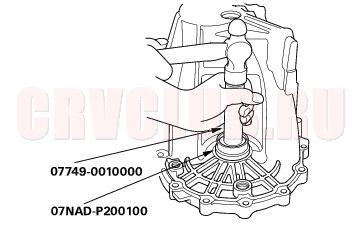
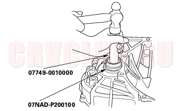
Special Tools Required
Driver 07749-0010000 Oil seal driver attachment 07NAD-P200100
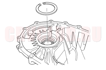
- Remove the differential assembly.
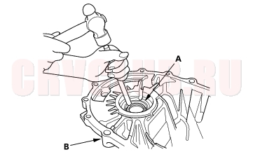
- Remove the oil seal (A) from the transmission housing (B).
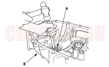
- Remove the oil seal (A) from the clutch housing (B).
- Install the new oil seal in the transmission housing with the special tools.
- Install the new oil seal in the clutch housing with the special tools.
Differential Thrust Clearance Adjustment13-61
Special Tool Required
Driver, 40 mm I.D. 07746-0030100
- Install the 80 mm shim that's the same size as the one you removed.
- Install the differential assembly into the clutch housing.
- Install the transmission housing onto the clutch housing, then tighten the 8 mm flange bolts in a crisscross pattern in several steps.
8 x 1.25 mm
27 N·m (2.8 kgf·m, 20 Ibf·ft)
- Use the special tool to bottom the differential assembly in the clutch housing.
- Measure clearance between 80 mm shim and bearing outer race in transmission housing.
Standard: 0 - 0.10 mm (0 - 0.004 in.)
- If the clearance is more than the standard, select a new shim from the following table. If the clearance measured in step 5 is within the standard, go to step 9.
- Remove the bolts and transmission housing.
- Replace the thrust shim selected in step 7, then recheck the clearance.
- Reinstall the transmission.
|
M/T - M/T Differential13-1
M/T Differential13-56 |