Manual Transmission13-2
|
M/T - M/T Differential13-1
Manual Transmission13-2 |
Manual Transmission13-2
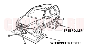
4WD (Four-wheel Drive) Model Precautions
This 4WD model does not have the feature that mechanically switches between 4WD and 2WD (front-wheel drive). Therefore, speedometer testing should be conducted using simplified free rollers under the rear wheels.
Precautions on using free rollers:
Inspecting and testing using a chassis dynamometer is not feasible. Do not operate the accelerator pedal, brake pedal or steering wheel abruptly. It may cause the vehicle to roll and create a hazardous condition. The maximum testing speed should be 50 km/h (31 mph). The maximum continuous operating time should be three minutes. Make sure to tie down the vehicle securely with the side anchor wires and center tie down wire. The free rollers are to be set under the rear wheels.
Testing Procedures
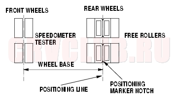
- Set the free rollers according to the wheel base and tread of the vehicle.
- NOTE: Align the position marker notch to the positioning line.
- Move the vehicle to position the front wheels on the speedometer testers and the rear wheels on the free rollers. Make sure to align the center of the wheels to the center of the speedometer testers and the free rollers.
- Tie down the vehicle securely using the towing hook and the rear tie-down hook bracket to prevent the vehicle from rolling off or over the free rollers.
- Start the engine, shift the transmission to 3rd gear, accelerate the vehicle gradually, and measure the vehicle speed.
- After measurement, use the brake pedal to gradually decelerate and stop the vehicle.
Special Tools13-3
* Part of Mainshaft Inspection Tool Set, 07GAJ-PG20102.
Transmission Fluid Inspection and Replacement13-4
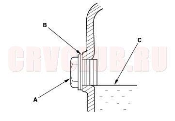
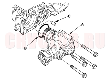
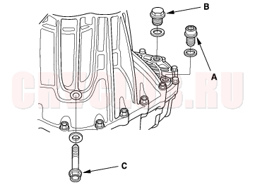
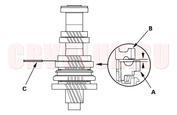
- Park the vehicle on level ground, and turn the engine OFF.
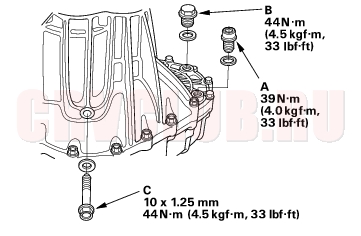
- Remove the oil filler plug (A) and washer (B), check the condition of the fluid, and make sure the fluid is at the proper level (C).
- If the transmission fluid is dirty, remove the drain plug (D) and drain the fluid.
- Reinstall the drain plug with a new washer, and refill the transmission fluid to the proper level.
Oil Capacity
2WD model:
1.9 l (1.9 US qt, 1.6 lmp qt) at fluid change
2.1 l (2.2 US qt, 1.8 lmp qt) at overhaul
4WD model:
1.9 l (2.0 US qt, 1.7 lmp qt) at fluid change
2.3 l (2.4 US qt, 2.0 lmp qt) at overhaul
Always use Honda Manual Transmission Fluid (MTF). Using motor oil can cause stiffer shifting because it does not contain the proper additives. Back-Up Light Switch Test13-4
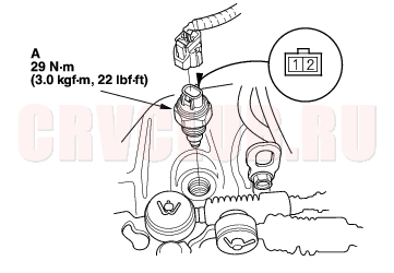
- Disconnect the back-up light switch (A) connector.
- Check for continuity between the back-up light switch 2P connector No. 1 and No. 2 terminals. There should be continuity when the shift lever is in reverse.
- If necessary, replace the back-up light switch. Apply liquid gasket (P/N 08C70-K0234M), and install it on the transmission housing.
Transmission Removal13-5
NOTE: Use fender covers to avoid damaging painted surfaces.
- Write down the frequencies for the radio's preset buttons. Disconnect the negative (-) cable first, then the positive (+) cable from the battery. Remove the battery.
- Remove the air cleaner housing (see step 5 on page 05-3 ).
- Remove the intake duct (see step 6 on page 05-3 ).
- Remove the battery tray (A).
- Disconnect the transmission ground cable (B).
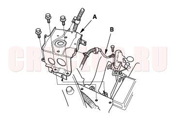
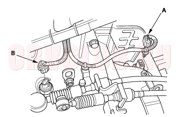
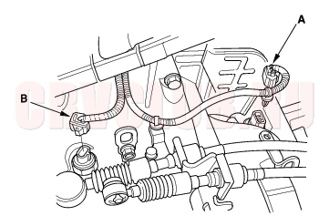
- Disconnect the vehicle speed sensor (A) and the back-up light switch connector (B).
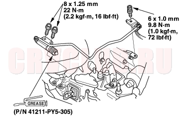
- Remove the cable bracket (A), then disconnect the cables (B) from the top of the transmission housing. Carefully remove both cables and the bracket together so as not to bend the cables.
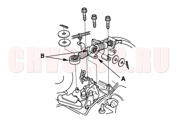
- Carefully remove the slave cylinder so as not to bend the clutch line. Do not operate the clutch pedal once the slave cylinder has been removed.
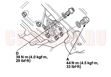
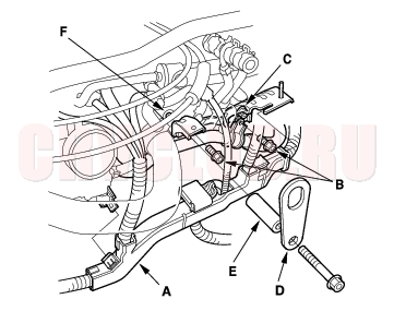
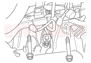
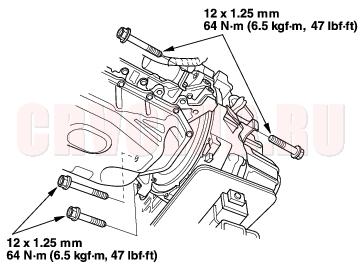
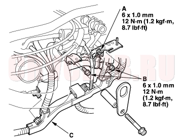
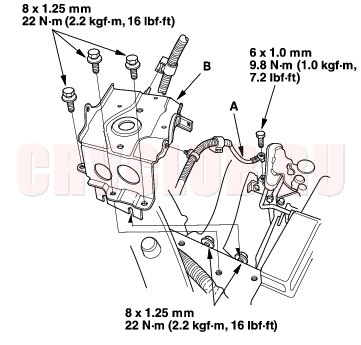
- Remove the harness cover (A), water pipe mounting bolts (B), and loosen the air cleaner housing mounting bracket bolt (C). Lower the water pipe slightly.
- Attach a engine hanger (D) with a collar (E) to the bolt hole (F) on the engine cylinder block.
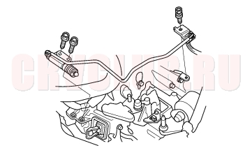
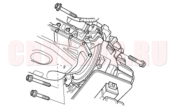
- Remove the two upper transmission mounting bolts.
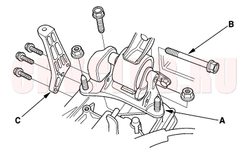
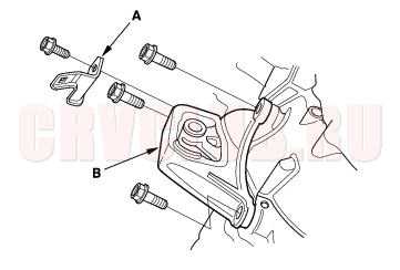
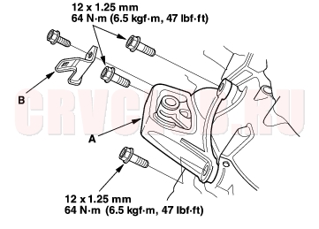
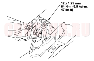
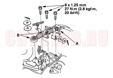
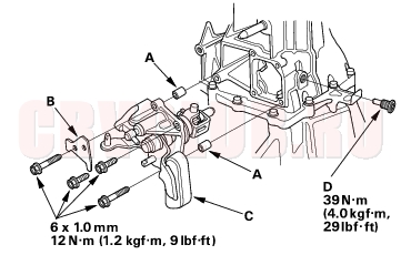
- Remove the transmission mount bracket (A) and transmission mounting bolt (B).
- Remove the air cleaner bracket (C).
- Raise vehicle and make sure it is securely supported.
- Drain the transmission fluid. Reinstall the drain bolt using a new washer (see page 13-4) .
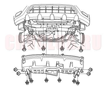
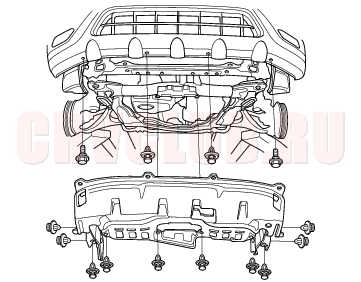
- Remove the splash shield.
- Remove the driveshafts (see page 16-3) .
- Remove the intermediate shaft (see page 16-19) .
- For 4WD models, remove the propeiler shaft (see page 16-33) .
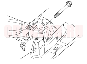
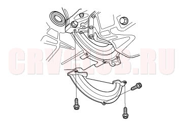
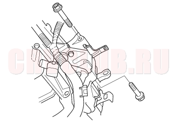
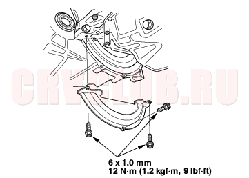
- Remove the front engine mount bracket mounting bolt.
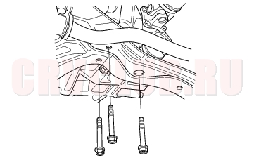
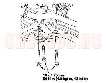
- Remove the three bolts securing the transmission rear mount.
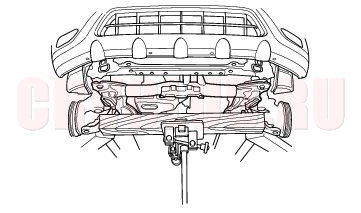
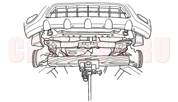
- Support the subframe with a 4 x 4 x 40 in. piece of wood and a jack.
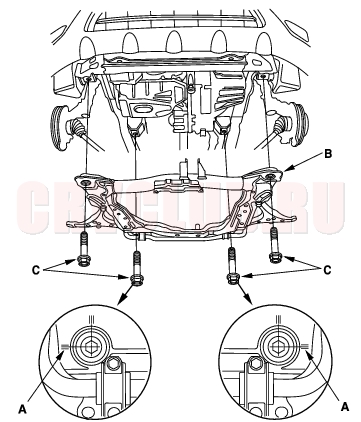
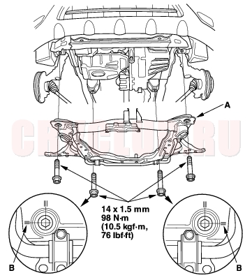
- Make reference marks (A) on the front suspension subframe (B) and mounting bolts (C), then remove the front suspension subframe.
2.0 l model:
2.4 l model:
- Remove the harness clamp (A).
- Remove the front engine mount (B).
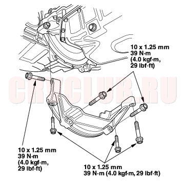
- Place the transmission jack under the transmission and remove the four lower transmission mounting bolts.
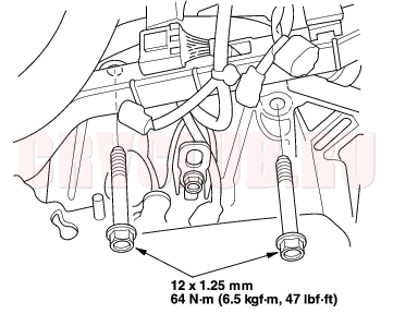
- Remove the two lower transmission mounting bolts.
- Pull the transmission away from the engine until the transmission mainshaft clears the clutch pressure plate, then lower the transmission on the transmission jack.
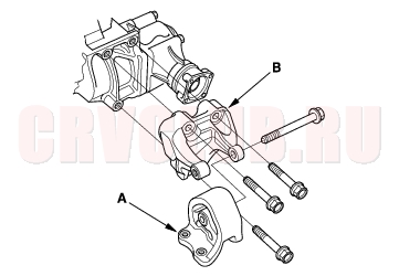
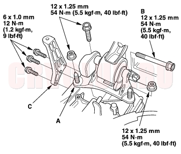
- Remove the transmission rear mount (A) and the transmission rear mount bracket (B).
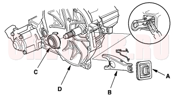
- Remove the boot (A), the release fork (B), and the release bearing (C) from the transmission (D).
Transmission Installation13-10
- Check the two dowel pins are installed in the clutch housing.
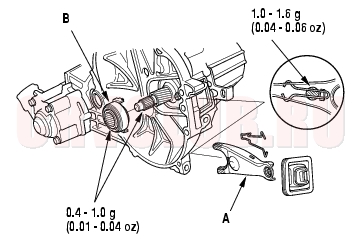
- Apply Urea Grease UM264 (P/N 41211-PY5-305) to the release fork (A) and the release bearing (B). Install the release fork and the release bearing.
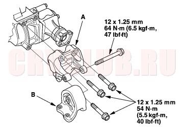
- Install the transmission rear mount bracket (A) and the transmission rear mount (B).
- Place the transmission on the transmission jack, and raise it to the engine level.
- Install the two lower transmission mounting bolts.
- Install the four lower transmission mounting bolts.
2.0 l model:
2.4 l model:
- Install the front suspension subframe (A) in its original position by aligning the marks (B) you made in the removal procedure.
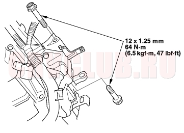
- Install the three rear mounting bolts for the transmission rear mount.
- Loosely tighten the front engine mount bracket mounting bolt.
- Install the intermediate shaft (see page 16-23) .
- Install the driveshafts (see page 16-17) .
- For 4WD models, Install the propeller shaft (see page 16-34) .
- Install the transmission mount bracket (A) and the transmission mounting bolt (B).
- Install the air cleaner bracket (C).
- Loosen the front engine mount bracket mounting bolt, then tighten the front engine mount bracket mounting bolt.
- Install the splash shield.
- Install the two upper transmission mounting bolts.
- Remove the chain hoist.
- Install the air cleaner housing mounting bracket bolt (A), water pipe mounting bolts (B), harness cover (C).
- Apply Urea Grease UM264 (P/N 41211-PY5-305) to the end of the cylinder rod. Install the slave cylinder. Take care not to bend the clutch line.
- Install the cable bracket (A) and cables (B).
- Connect the vehicle speed sensor (A) and the back-up light switch connector (B).
- Install the transmission ground cable (A).
- Install the battery tray (B).
- Install the intake duct (see step 38 on page 05-16 ).
- Install the air cleaner housing (see step 39 on page 05-17 ).
- Install the battery. Connect the positive (+) cable first, then the negative (-) cable to the battery.
- Refill the transmission fluid (see page 13-4) .
- Test-drive the vehicle.
- Check the clutch operation.
- Check the front wheel alignment (see page 18-4) .
- Enter the anti-theft code for the radio, then enter the customer's radio station presets.
Transmission Disassembly13-15
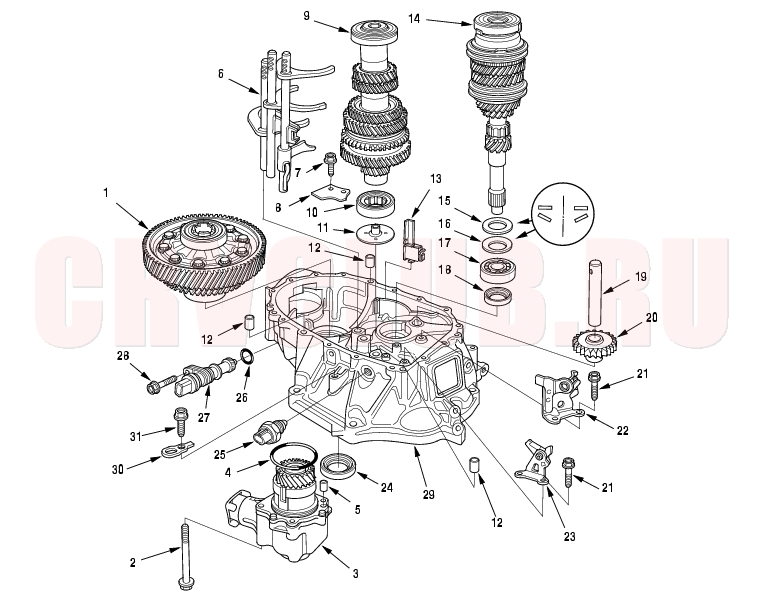
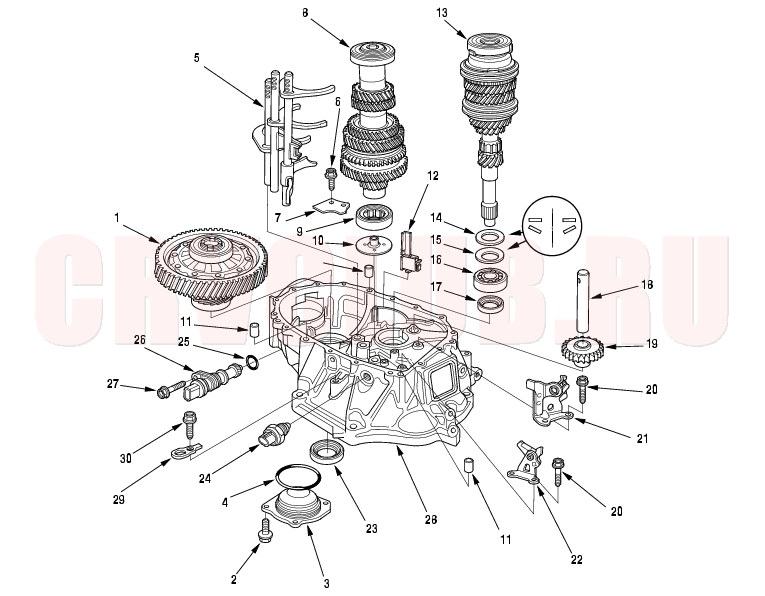
Exploded View-Clutch Housing
4WD model
2WD model
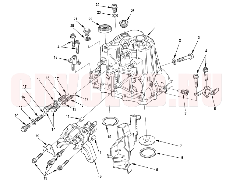
Exploded View-Transmission Housing
NOTE: Place the clutch housing on two pieces of wood thick enough to keep the mainshaft from hitting the workbench.
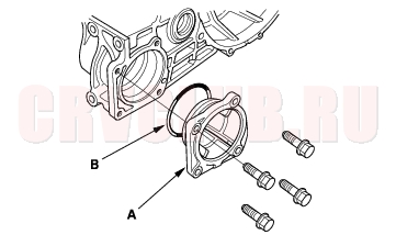
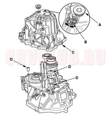
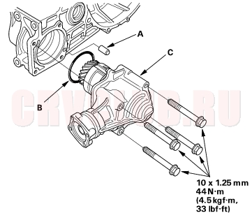
- Remove the transfer assembly (A), O-ring (B) and 10 x 20 mm dowel pin (C). (4WD model)
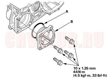
- Remove the side cover (A) and O-ring (B). (2WD model)
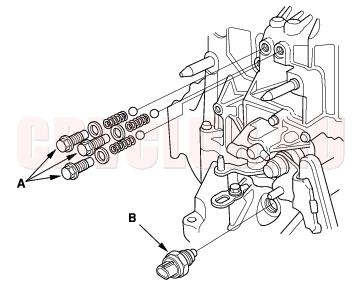
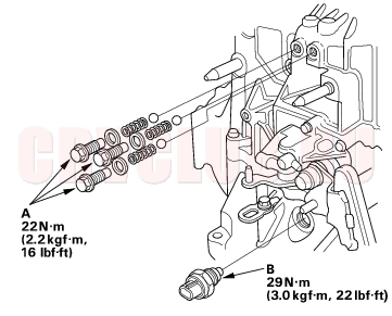
- Remove the detent bolts (A), springs, steel balls and back-up light switch (B).
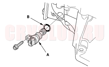
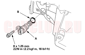
- Remove the vehicle speed sensor (VSS)(A) and O-ring (B).
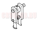
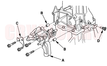
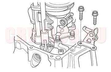
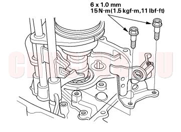
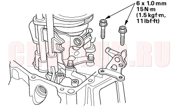
- Remove the change lever assembly (A), 8 x 14 mm dowel pins (B), clutch line clip bracket (C) and interlock bolt (D).
- Remove the drain plug (A), filler plug (B) and 10 mm flange bolt (C).
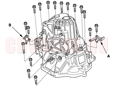
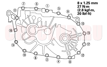
- Remove the 8 mm flange bolts in a crisscross pattern in several steps.
- Remove the transmission hanger A and transmisson hanger B.
- Remove the 32 mm sealing cap (A).
- Expand the 72 mm snap ring (B) on the countershaft ball bearing, and remove it from the groove using a pair of snap ring pliers.
- Remove the transmission housing (C) and 14 x 20 mm dowel pins (D).
- Remove the reverse lock cam.
- Remove the reverse idler gear (A) and reverse gear shaft (B).
- Remove the reverse shift fork.
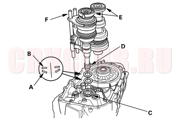
- Apply tape to the mainshaft splines to protect the seal, then remove the mainshaft assembly (A) and countershaft assembly (B) with the shift forks (C) from the clutch housing (D).
- Remove the 28 mm spring washer (E) and 28 mm washer (F).
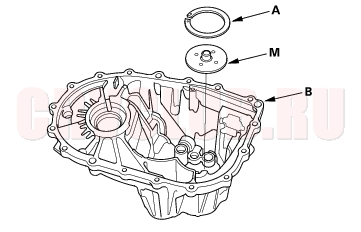
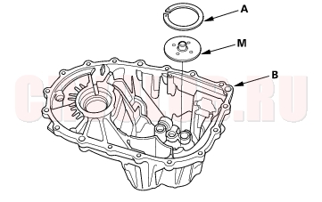
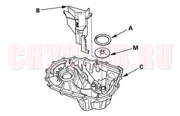
- Remove the differential assembly (A) and magnet (B).
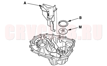
- Remove the oil gutter plate (A), 72 mm shim (B) and oil guide plate M.
Reverse Shift Fork Clearance Inspection13-21
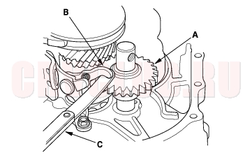
- Measure the clearance between the reverse idler gear (A) and the reverse shift fork (B) with a feeler gauge (C). If the clearance is more than the service limit, go to step 2.
Standard: 0.20 - 0.59 mm (0.007 - 0.023 in.)
Service Limit: 1.2 mm (0.047 in.)
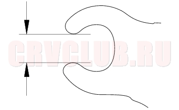
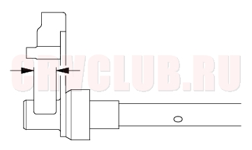
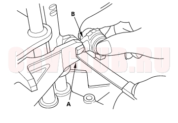
- Measure the width of the reverse shift fork.
- If distance is not within the standard, replace the reverse shift fork with a new one.
- If distance is within the standard, replace the reverse gear with a new one.
Standard: 13.4 - 13.7 mm (0.527 - 0.539 in.)
Shift Lever Clearance Inspection13-22
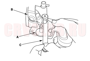
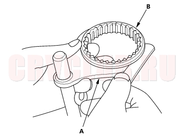
- Measure the clearance between shift lever (A) and the select lever (B) with a feeler gauge (C). If the clearance is more than the service limit, go to step 2.
Standard: 0.05 - 0.25 mm (0.002 - 0.010 in.)
Service Limit: 0.50 mm (0.020 in.)
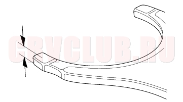
- Measure the groove of the shift lever.
- If distance is not within the standard, replace the shift lever with a new one.
- If distance is within the standard, replace the select lever with a new one.
Standard: 15.00 - 15.10 mm (0.591 - 0.594 in.)
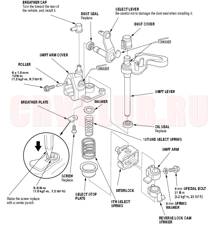
Change Lever Assembly Disassembly/Reassembly13-23
Prior to reassembling, clean all the parts in solvent, dry them, and apply lubricate to any contact surface.
Shift Forks Clearance Inspection13-24
NOTE: The synchro sleeve and synchro hub should be replaced as a set.
- Measure the clearance between each shift fork (A) and its matching synchro sleeve (B). If the clearance exceeds the service limit, go to step 2.
Standard: 0.35 - 0.65 mm (0.014 - 0.026 in.)
Service Limit: 1.0 mm (0.039 in.)
- Measure the thickness of the shift fork fingers.
- If the thickness of the shift fork finger is not within the standard, replace the shift fork with a new one.
- If the thickness of the shift fork finger is within the standard, replace the synchro sleeve with a new one.
Standard: 7.4 - 7.6 mm (0.29 - 0.30 in.)
- Measure the clearance between the shift fork (A) and the shift arm (B). If the clearance exceeds the service limit, go to step 4.
Standard: 0.2 - .5 mm (0.008 - 0.020 in.)
Service Limit: 0.60 mm (0.023 in.)
- Measure the width of the shift arm.
- If the width of the shift arm is not within the standard, replace the shift arm with a new one.
- If the width of the shift arm is within the standard, replace the shift fork or shift piece with a new one.
Standard: 16.9 - 17.0 mm (0.665 - 0.669 in.)
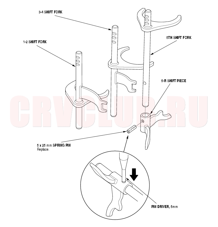
Shift Forks Disassembly/Reassembly13-25
Prior to reassembling, clean all the parts in solvent, dry them, and apply lubricant to any contact parts.
Mainshaft Assembly Clearance Inspection13-26
NOTE: If replacement is required, always replace the synchro sleeve and hub as a set.
- Support the bearing inner race with an appropriate sized socket (A), and push down on the mainshaft (B).
Standard: 0.06 - 0.16 mm
(0.002 - 0.006 in.)
Service Limit: 0.25 mm (0.010 in.)
- Measure the clearance between 2nd (C) and 3rd (D) gears with a feeler gauge (E).
- If the clearance is more than the service limit, go to step 3.
- If the clearance is within the service limit, go to step 4.
- Measure the thickness of 3rd gear.
- If the thickness of 3rd gear is less than the service limit, replace 3rd gear with a new one.
- If the thickness of 3rd gear is within the service limit, replace the 3rd/4th synchro hub with a new one.
Standard: 23.92 - 23.97 mm
(0.981 - 0.944 in.)
Service Limit: 23.80 mm (0.937 in.)
- Measure the clearance between 4th gear (A) and the spacer collar (B) with a dial indicator (C). If the clearance is more than the service limit, go to step 5.
Standard: 0.06 - 0.16 mm
(0.002 - 0.006 in.)
Service Limit: 0.25 mm (0.010 in.)
- Measure distance [a] on the distance collar.
- If distance a is not within the standard, replace the distance collar with a new one.
- If distance [a] is within the standard, go to step 6.
Standard: 24.03 - 24.08 mm
(0.946 - 0.947 in.)
- Measure the thickness of 4th gear.
- If the thickness of 4th gear is less than the service limit, replace 4th gear with a new one.
- If the thickness of 4th gear is within the service limit, replace the 3rd/4th synchro hub with a new one.
Standard: 23.92 - 23.97 mm
(0.981 - 0.944 in.)
Service Limit: 23.80 mm (0.937 in.)
- Measure the clearance between the distance collar (A) and 5th gear (B) with a dial indicator (C). If the clearance is more than the service limit, go to step 8.
Standard: 0.06 - 0.16 mm
(0.002 - 0.006 in.)
Service Limit: 0.25 mm (0.010 in.)
- Measure distance b on the distance collar.
- If distance [b] is not within the standard, replace the distance collar with a new one.
- If distance [b] is within the standard, go to step 9.
Standard: 24.03 - 24.08 mm
(0.946 - 0.947 in.)
- Measure the thickness of 5th gear.
- If the thickness of 5th gear is less than the service limit, replace 5th gear with a new one.
- If the thickness of 5th gear is within the service limit, replace the 5th synchro hub with a new one.
Standard: 23.92 - 23.97 mm
(0.981 - 0.944 in.)
Service Limit: 23.80 mm (0.937 in.)
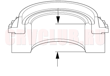
- Measure the thickness of the MBS distance collar.
- If the thickness of MBS distance collar is not within standard, replace the MBS distance collar with a new one.
Standard: 23.95 - 24.05 mm
(0.943 - 0.947 in.)
Mainshaft Disassembly13-28
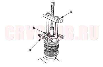
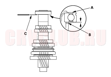
- Remove the angular ball bearing (A) and the tapered cone ring using a commercially available bearing separator (B) and a commercially available bearing puller (C). Be sure the bearing separator is under the tapered cone ring.
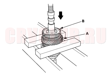
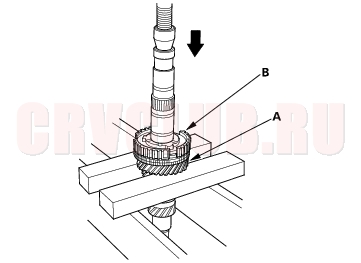
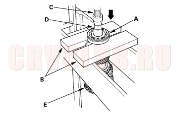
- Support 5th gear (A) on steel blocks, and press the mainshaft out of the 5th synchro hub (B). Use of a jaw-type puller can damage the gear teeth.
- Support the 3rd gear (A) on steel blocks, and press the mainshaft out of the 3rd/4th synchro hub (B). Use of a jaw-type puller can damage the gear teeth.
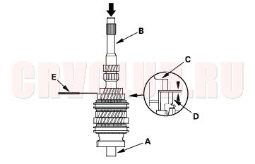
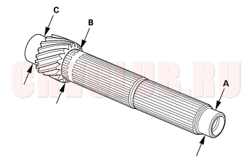
Mainshaft Inspection13-29
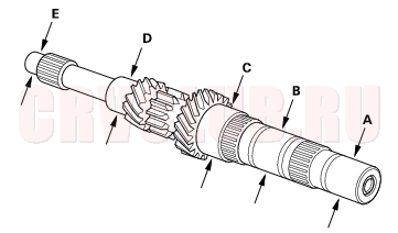
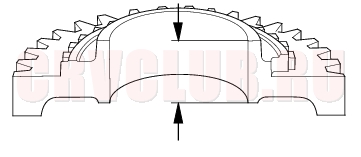
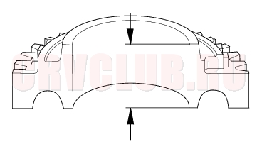
- Inspect the gear surface and bearing surface for wear and damage, then measure the mainshaft at points A, B, and C. If any part of the mainshaft is less than the service limit, replace it with a new one.
Standard:
A Ball bearing surface (transmission housing side):
27.987 - 28.000 mm (1.1019-1.1024 in.)
B Distance collar surface:
31.984 - 32.000 mm (1.2594 - 1.2598 in.)
C Needle bearing surface:
38.984 - 39.000 mm (1.5348 - 1.5354 in.)
D Ball bearing surface (clutch housing side):
27.977 - 27.990 mm (1.1015 - 1.1020 in.)
E Bush surface:
20.80 - 20.85 mm (0.8189 - s0.8209 in.)
Service Limit:
A: 27.94 mm (1.100 in.)
B: 31.93 mm (1.257 in.)
C: 38.93 mm (1.533 in.)
D: 27.94 mm (1.100 in.)
E: 20.75 mm (0.817 in.)
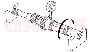
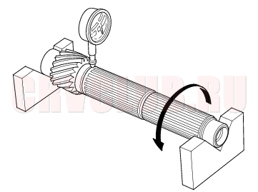
- Inspect the runout by supporting both ends of the mainshaft. Rotate the mainshaft two complete revolutions when measuring the runout. If the runout is more than the service limit, replace the mainshaft with a new one.
Standard: 0.02 mm (0.001 in.) max.
Service Limit: 0.05 mm (0.002 in.)
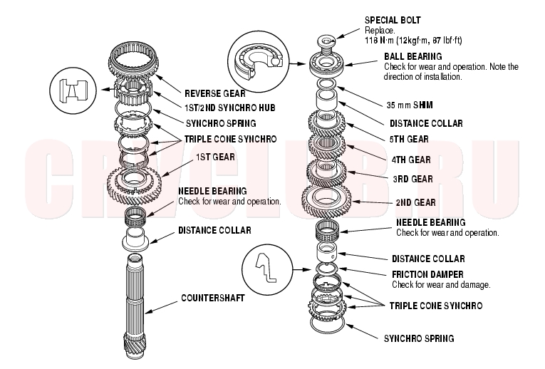
Mainshaft Reassembly13-31
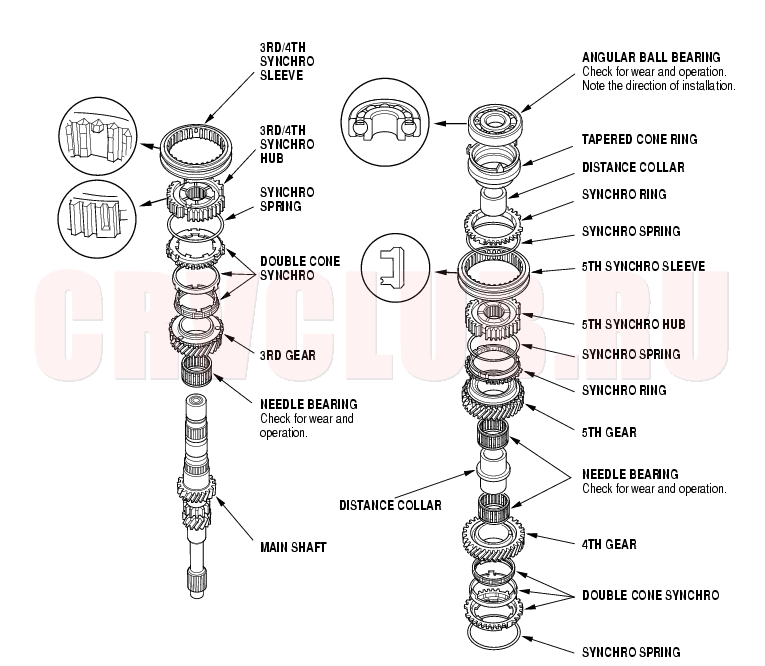
Exploded View
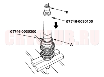
Special Tools Required
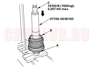
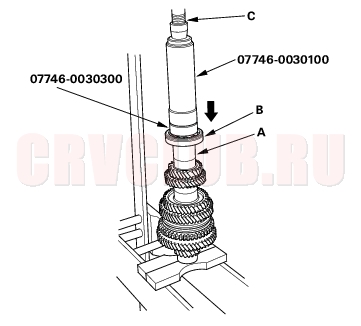
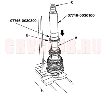
Driver, 40 mm I.D. 07746-0030100 Attachment, 30 mm I.D. 07746-0030300
Refer to the Exploded View as needed during this procedure.
- Clean all the parts in solvent, dry them, and apply lubricant to all contact surfaces except the 3rd/4th and 5th synchro hubs.
- Install the needle bearing and 3rd gear on the mainshaft.
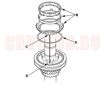
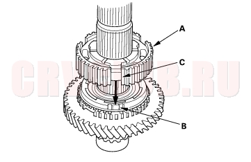
- Install the double cone synchro assembly (A) by aligning the synchro cone fingers (B) with the holes in 3rd gear (C), then install the synchro spring (D).
- Install the 3rd/4th synchro hub (A) by aligning the synchro cone fingers (B) with the grooves in 3rd/4th synchro hub (C).
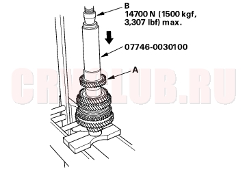
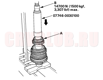
- Install the 3rd/4th synchro hub (A) using the special tool.
- Install the 3rd/4th synchro sleeve (A) by aligning the stops (B) with the 3rd/4th synchro sleeve and hub. After installing, check the operation of the 3rd/4th synchro hub set.
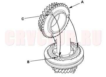
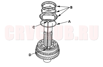
- Install the synchro spring (A).
- Install the double cone synchro assembly (B) by aligning the synchro cone fingers (C) with the grooves in 3rd/4th synchro hub (D).
- Install the 4th gear (A) by aligning the synchro cone fingers (B) with holes in 4th gear (C).
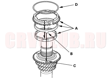
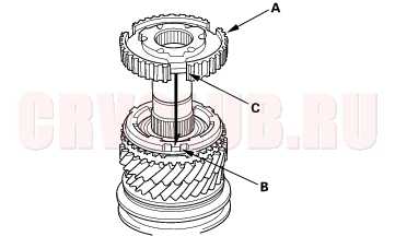
- Install the needle bearings, distance collar, 5th gear, and 5th gear synchro spring and ring.
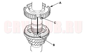
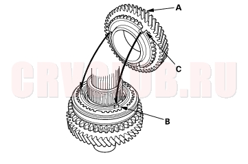
- Install the 5th synchro hub (A) by aligning the synchro cone fingers (B) with the grooves in 5th/6th synchro hub (C).
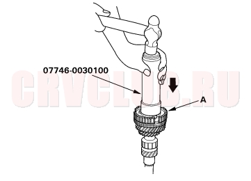
- Install the 5th synchro hub (A) using the special tools.
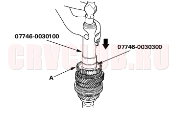
- Install the 5th synchro sleeve.
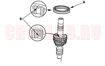
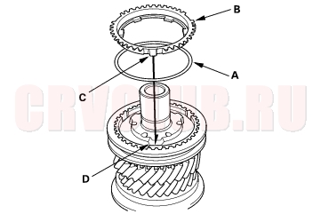
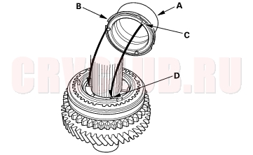
- Install the synchro spring (A).
- Install the synchro ring (B) by aligning the synchro cone fingers (C) with the grooves in 5th synchro hub (D).
- Install the new ball bearing (A) using the special tools and press (B).
Countershaft Assembly Clearance Inspection13-34
- Measure the clearance between the 1st gear (A) and the distance collar (B) with a feeler gauge (C). If the clearance is more than the service limit, go to step 2.
Standard: 0.06 - 0.16 mm (0.002 - 0.006 in.)
Service Limit: 0.25 mm (0.010 in.)
- Measure the thickness of the distance collar.
- If the thickness is not within the standard, replace the distance collar with a new one.
- If the thickness is within the standard, go to step 3.
Standard: 23.03 - 23.08 mm (0.907 - 0.909 in.)
- Measure the thickness of the 1st gear.
- If the thickness of 1st gear is less than the service limit, replace 1st gear with a new one.
- If the thickness of 1st gear is within the service limit, replace the 1st/2nd synchro hub with a new one.
Standard: 22.92 - 22.97 mm (0.902 - 0.904 in.)
Service Limit: 22.87 mm (0.900 in.)
- Measure the clearance between the 2nd gear (A) and 3rd gear (B) with a feeler gauge (C). If the clearance is more than the service limit, go to step 5.
Standard: 0.06 - 0.16 mm (0.002 - 0.006 in.)
Service Limit: 0.25 mm (0.010 in.)
- Measure the thickness of the distance collar.
- If the thickness is not within the standard, replace the distance collar with a new one.
- If the thickness is within the standard, go to step 6.
Standard: 28.03 - 28.08 mm (1.104 - 1.106 in.)
- Measure the thickness of the 2nd gear.
- If the thickness of 2nd gear is less than the service limit, replace 2nd gear with new one.
- If the thickness of 1st gear is within the service limit, replace the 1st/2nd synchro hub with a new one.
Standard: 27.92 - 27.97 mm (1.099 - 1.101 in.)
Service Limit: 27.87 mm (1.097 in.)
Countershaft Disassembly13-36
- Securely clamp the countershaft assembly in a bench vise with wood blocks.
- Remove the special bolt (left-hand threads).
- Support ball bearing (A) on steel blocks (B), then use a press (C) and an attachment (D) to press the countershaft out of the ball bearing.
- Remove the 35 mm shim and distance collar.
- Support 4th gear (A) on steel blocks (B), then use a press (C) and an attachment (D) to press the countershaft (E) out of the 5th gear.
- Support 2nd gear (A) on steel blocks (B), then use a press (C) and an attachment (D) to press the countershaft (E) out of the 3rd gear.
Countershaft Inspection13-37
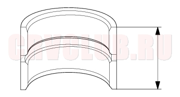
- Inspect the gear surface and bearing surface for wear and damage, then measure the countershaft at points A, B, and C. If any part of the countershaft is less than the service limit, replace it with a new one.
Standard:
A Ball bearing surface (transmission housing side):
30.020 - 30.033 mm (1.1819 - 1.1824 in.)
B Distance collar surface:
39.937 - 39.950 mm (1.5723 - 1.5728 in.)
C Needle bearing surface (clutch housing side):
35.000 - 35.015 mm (1.3780 - 1.3785 in.)
Service Limit:
A: 29.97 mm (1.180 in.)
B: 39.88 mm (1.570 in.)
C: 34.95 mm (1.376 in.)
- Inspect the runout by supporting both ends of the countershaft, Rotate the countershaft two complete revolutions when measuring the runout. If the runout exceeds the service limit, replace the countershaft with a new one.
Standard: 0.02 mm (0.001 in.) max.
Service Limit: 0.05 mm (0.002 in.)
Countershaft Reassembly13-38
Exploded View
Special Tools Required
Attachment, 42 x 47 mm 07746-0010300 Driver, 40 mm I.D. 07746-0030100 Attachment, 30 mm 07746-0030300 Driver 07749-0010000 NOTE: Refer to the Exploded View as needed during this procedure.
- Clean all parts in solvent, dry them, and apply lubricant to all contact surfaces.
- Install the distance collar and needle bearing onto the countershaft.
- Install the triple cone synchro assembly (A) by aligning the synchro cone fingers (B) with 1st gear grooves (C), then install the synchro spring (D).
- Install the 1st/2nd synchro hub (A) by aligning the synchro cone fingers (B) with 1st/2nd synchro hub grooves (C).
- Install the reverse gear.
- Install the synchro spring (A).
- Install the triple cone synchro assembly (B) by aligning the synchro cone fingers (C) with 1st/2nd synchro hub grooves (D).
- Install the distance collar (A) and friction damper (B) by aligning the friction damper fingers (C) with 1st/2nd synchro hub grooves (D).
- Install the needle bearing.
- Install the 2nd gear (A) by aligning the synchro cone fingers (B) with 2nd gear grooves (C).
- Support the countershaft (A) on the steel blocks, then install the 3rd gear (B) using the special tool and a press (C). Do not exceed the maximum pressure.
- Install the 4th gear (A) using the special tool and a press (B). Do not exceed the maximum pressure.
- Install the 5th gear (A) using the special tool and a press (B). Do not exceed the maximum pressure.
- Install the distance collar (A), 35 mm shim, and old ball bearing (B) using a special tools and a press (C).
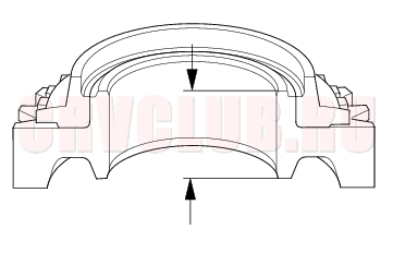
- Measure the clearance between the old bearing (A) and the 35 mm shim (B) with a feeler gauge (C).
Standard: 0.04 - 0.10 mm (0.002 - 0.004 in.)
- If the clearance is more than the standard, select a new shim from the following table. If the clearance measured in step 15 is within the standard, replace the new ball bearing.
- Support ball bearing (A) on steel blocks (B), then use a press (C) and an attachment (D) to press the countershaft (E) out of the ball bearing.
- Replace the 35 mm shim selected in step 16, then recheck the clearance.
- Install the distance collar (A) 35 mm shim, and new ball bearing (B) using a special tools and a press (C).
- Tighten the new special bolt (A) (left-hand threads).
Synchro Sleeve and Hub Inspection and Reassembly13-43
- Inspect gear teeth on all synchro hubs and synchro sleeves for rounded off corners, which indicate wear.
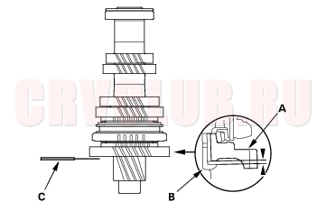
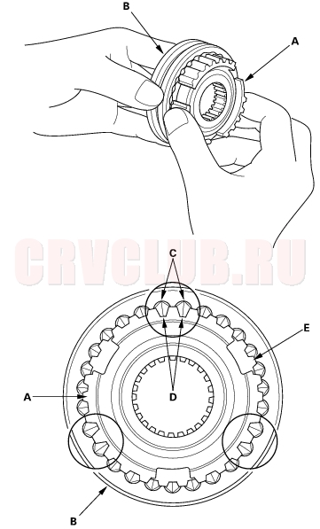
- Install each synchro hub (A) in its mating synchro sleeve (B), and check for freedom of movement. Be sure to match the 3 sets of longer teeth (C) (120 degrees apart) on the synchro sleeve with the 3 sets of deeper grooves (D) in the synchro hub. Do not install the synchro sleeve with its longer teeth in the 1st/2nd synchro hub slots (E) because it will damage the spring ring.
- NOTE: If replacement is required, always replace the synchro sleeve and synchro hub as a set.
Synchro Ring and Gear Inspection13-43
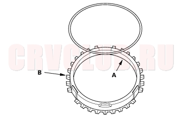
- Inspect the inside of each synchro ring (A) for wear. Inspect the teeth (B) on each synchro ring for wear (rounded off).
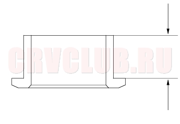
- Inspect the teeth (C) on each synchro sleeve and matching teeth on each gear for wear (rounded off).
Example of synchro sleeve teeth and gear teeth
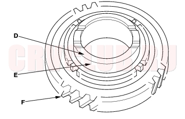
- Inspect the thrust surface (D) on each gear hub for wear.
- Inspect the cone surface (E) on each gear hub for wear and roughness.
- Inspect the teeth on all gears (F) for uneven wear, scoring, galling, and cracks.
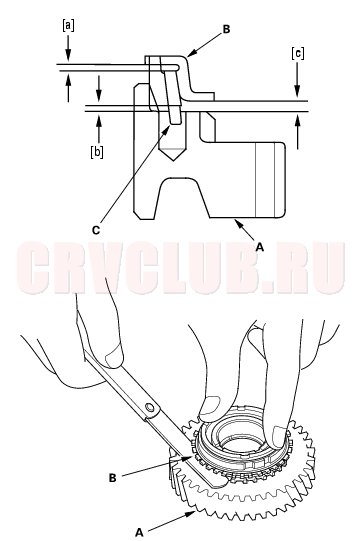
- Coat the cone surface of each gear (E) with oil, and place its synchro ring on it. Rotate the synchro ring, making sure that it does not slip.
- Measure the clearance between each gear (A) and its synchro ring (B) all the way around. Hold the synchro ring against the gear evenly while measuring the clearance. If the clearance is less than the service limit, replace the synchro ring and gear.
Synchro Ring-to-Gear Clearance
Standard: 0.70 - 1.49 mm (0.028 - 0.059 in.)
Service Limit: 0.4 mm (0.016 in.)
Double cone synchro and triple cone synchro-to-Gear Clearance
Standard:
[a]: Outer Synchro Ring (B) to Synchro Cone (C)
0.70 - 1.19 mm (0.028 - 0.047 in.)
[b]: Synchro Cone (C) to Gear (A)
0.50 - 1.04 mm (0.020 - 0.041 in.)
[c]: Outer Synchro Ring (B) to Gear (A)
0.95 - 1.68 mm (0.037 - 0.066 in.)
Service Limit:
[a]: 0.3 mm (0.012 in.)
[b]: 0.3 mm (0.012 in.)
[c]: 0.6 mm (0.024 in.)
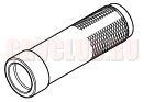
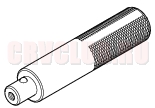
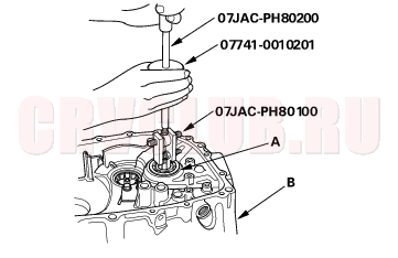
Mainshaft Bearing and Oil Seal Replacement13-45
Special Tools Required
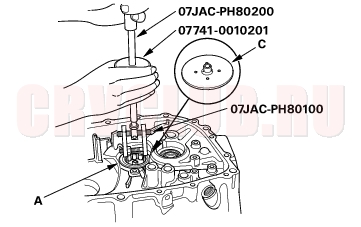
Adjustable bearing puller, 25 - 40 mm 07JAC-PH80100 Bearing remover shaft 07JAC-PH80200 Oil seal driver 07JAD-PL90100 Slide hammer 07741-0010201 Driver 07749-0010000 Attachment, 42 x 47 mm 07746-0010300
- Remove the differencial assembly.
- Remove the ball bearing (A) from the clutch housing (B) using the special tools.
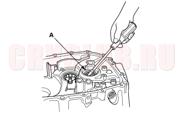
- Remove the oil seal (A) from the clutch side.
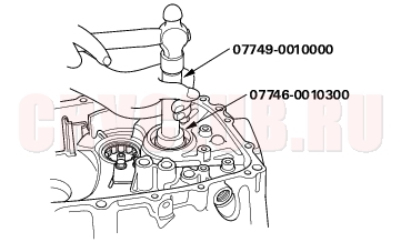
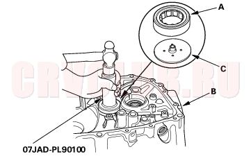
- Drive the new oil seal in from the transmission side using the special tools.
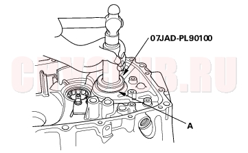
- Drive the new ball bearing (A) in from the transmission side using the special tools.
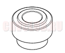
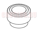
Countershaft Bearing Replacement13-46
Special Tools Required
Adjustable bearing puller, 25 - 40 mm 07JAC-PH80100 Bearing remover shaft 07JAC-PH80200 Slide hammer 07741-0010201 Oil seal driver 07JAD-PL90100
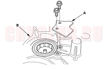
- Remove the bearing set plate (A) from the clutch housing (B).
- Remove the needle bearing (A) using the special tools, then remove the oil guide plate C.
- Position the oil guide plate C and new needle bearing (A) in the bore of the clutch housing (B).
- Install the needle bearing using the special tools.
- Install the bearing set plate (A) with bolts (B).
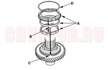
Mainshaft Thrust Clearance Adjustment13-47
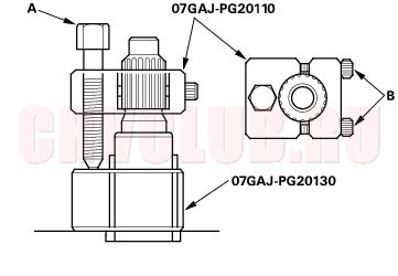
Special Tools Required
Mainshaft base 07GAJ-PG20130 Mainshaft holder 07GAJ-PG20110
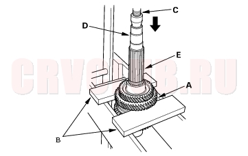
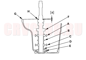
- Remove the 72 mm shim (A) and oil guide plate M from the transmission housing (B).
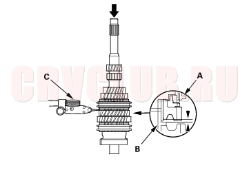
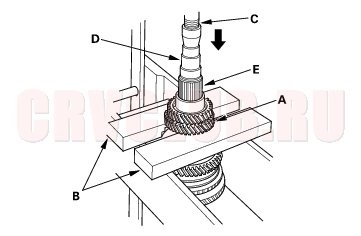
- Install the 3rd/4th synchro hub (A), the distance collar (B), the 5th synchro hub (C), distance collar (D), and ball bearing (E) on the mainshaft (F), then install the assembled mainshaft in the transmission housing (G).
- Install the washer (H) on the mainshaft.
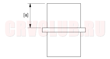
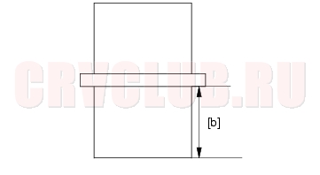
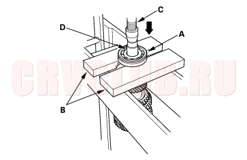
- Measure distance [a] between the end of the transmission housing and washer with a straight edge and vernier caliper. Measure at three locations and average the reading.
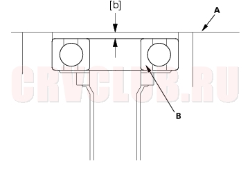
- Measure distance [b] between the end of the clutch housing (A) and bearing inner race (B) with a straight edge and depth gauge. Measure at three locations and average the readings.
Shim Selection Formula:
- Select the proper 72 mm shim from the chart. Follow the example below, and use the measurements you made in steps 4 and 5:
- (Basic Formula)
- [a] + [b] - (0.8 + 0.11) = shim thickness (maximum)
- [a] + [b] - (0.8 + 0.17) = shim thickness (minimum)
- Add distance [b] (step 5) to distance [a] (step 4).
- 0.8 mm (0.031 in): Spring washer, a dimension in the installation.
- 0.11 mm (0.004 in): Minimum thrust clearance.
- 0.17 mm (0.007 in): Maximum thrust clearance.
- (For example)
- 2.32 + 0.15 - (0.8 + 0.11) = 1.56 mm (0.061 in.)
- 2.32 + 0.15 - (0.8 + 0.17) = 1.50 mm (0.059 in.)
- Take the middle value of the minimum value and the maximum value, and select shim of 1.53 mm (0.060 in.).
- Install the 72 mm shim (A) selected and oil guide plate M in the transmission housing (B).
- Throughly clean the spring washer (A) and washer (B) before installing them on the clutch housing side ball bearing (C). Note the installation direction of the spring washer.
- Install the mainshaft in the clutch housing.
- Place the transmission housing over the mainshaft and onto the clutch housing.
- Tighten the clutch and transmission housings with several 8 mm bolts.
- NOTE: It is not necessary to use sealing agent between the housings.
- Tap the mainshaft with a plastic hammer.
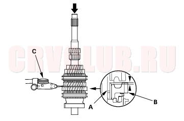
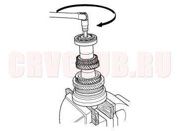
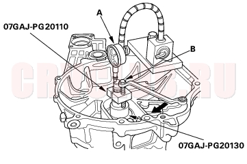
- Attach the special tool to the mainshaft as follows:
- Back-out the mainshaft holder bolt (A) and loosen the two hex bolts (B).
- Fit the holder over the mainshaft so its lip is towards the transmission.
- Align the mainshaft holder's lip around the groove at the inside of the mainshaft splines, then tighten the hex bolts.
- Seat the mainshaft fully by tapping its end with a plastic hammer.
- Thread the mainshaft holder bolt in until it just contacts the wide surface of the mainshaft base.
- Zero a dial gauge (A) on the end of the mainshaft.
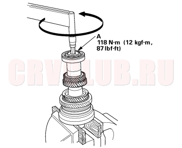
- Turn the mainshaft holder bolt (B) clockwise; stop turning when the dial gauge (A) has reached its maximum movement. The reading on the dial gauge is the amount of mainshaft end play.
- Do not turn the mainshaft holder bolt more than 60 degrees after the needle of the dial gauge stops moving, this may damage the transmission.
- If the reading is within the standard, the clearance is correct. If the reading is not within the standard, recheck the shim thickness.
Standard: 0.11 - 0.17 mm (0.004 - 0.007 in.)
Transmission Reassembly13-50
NOTE: Prior to reassembling, clean all the parts in solvent, dry them, and apply lubricant to any contact surfaces.
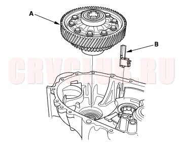
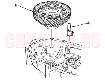
- Install the magnet (A) and differential assembly (B).
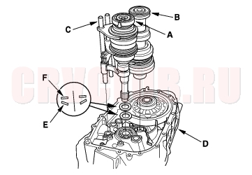
- Install the 28 mm spring washer (A) and 28 mm washer (B) over the ball bearing (C). Note the installation direction of the spring washer (A).
- Apply vinyl tape the mainshaft splines (D) to protect the seal. Install the mainshaft and countershaft (E) into the shift forks (F), and install them as an assembly.
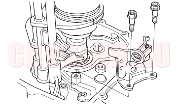
- Install the reverse shift fork.
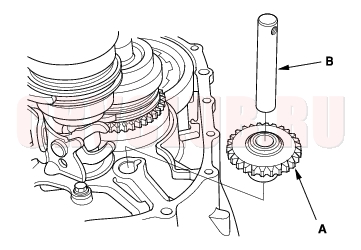
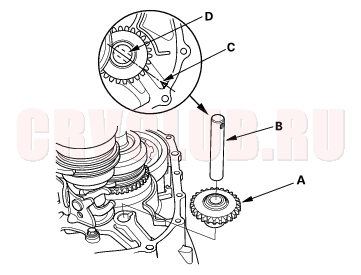
- Install the reverse idler gear (A) and reverse gear shaft (B) by aligning the mark (C) with reverse gear shaft hole (D).
- Install the reverse lock cam.
- Select the proper size 72 mm shim (A) according to the measurements made during the Mainshaft Thrust Clearance Adjustment (see page 13-47) . Install the oil gutter plate (B), oil guide plate M, and 72 mm shim into the transmission housing (C).
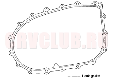
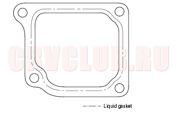
- Remove the dirt and oil from the tramsmission housing sealing surface. Apply liquid gasket (P/N 08C70-K0234M) to the sealing surface. Be sure to seal the entire circumference of the bolt holes to prevent oil leakage.
- NOTE: If 5 minutes have passed after applying liquid gasket, reapply it and assemble the housings. Allow it to cure at least 20 minutes after assembly before filling the transmission with oil.
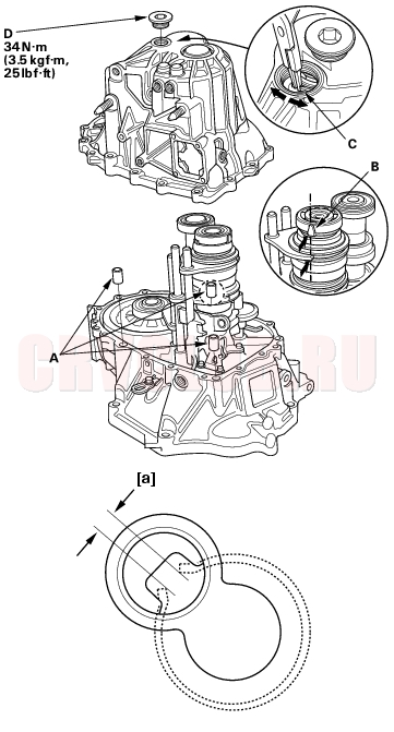
- Install the 14 x 20 mm dowel pins (A).
- Set the tapered cone ring (B) as shown. Place the transmission housing over the clutch housing, being careful to line up the shafts.
- Lower the transmission housing the rest of the way as you expand the 72 mm snap ring (C). Release the snap ring so it seats in the groove of the countershaft bearing.
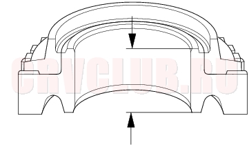
- Check that the 52 mm snap ring is securely seated in the groove of the countershaft bearing.
Dimension [a] as installed: 3.3 - 6.0 mm
(0.13 - 0.24 in.)
- Apply liquid gasket (P/N 08C70-K023M) to the threads of the 32 mm sealing cap (D), and install it on the transmission housing.
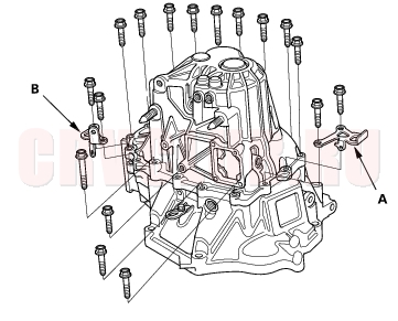
- Install the transmission hangers A, B, and the 8 mm flange bolts finger-tight.
- Tighten the 8 mm flange bolts in a crisscross pattern in several steps.
- Remove the dirt and oil from the shift lever cover sealing surface. Apply liquid gasket (P/N 08C70-K0234M) to the sealing surface.
- NOTE: If 5 minutes have passed after applying liquid gasket, reapply it and assemble the housings. Allow it to cure at least 20 minutes after assembly before filling the transmission with oil.
- Install the 8 x 14 mm dowel pins (A) clutch line clip bracket (B), and change lever assembly (C).
- Apply liquid gasket (P/N 08C70-K0234M) to the threads of the interlock bolt (D), and install it on the transmission housing.
- Install the drain plug (A), filler plug (B) and 10 mm flange bolt (C) with new washers.
- Install the detent bolts (A), spring, steel balls, with new washers.
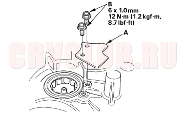
- Apply liquid gasket (P/N 08C70-K0234M) to the threads of the back-up light switch (B), and install it on the transmission housing.
- Install the vehicle speed sensor (VSS) (A) and O-ring (B).
- Install the O-ring (A) and side cover (B). (2WD model)
- Install the 10 x 20 mm dowel pin (A), O-ring (B), and transfer assembly (C). (4WD model)
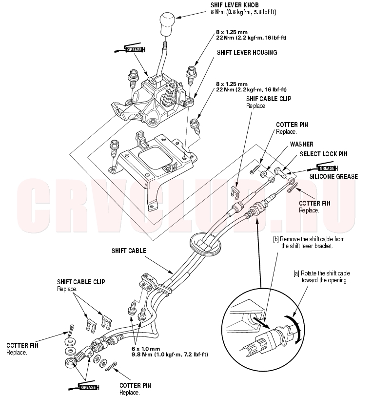
Gearshift Mechanism Replacement13-55
|
M/T - M/T Differential13-1
Manual Transmission13-2 |