Transfer Assembly13-63
|
M/T - M/T Differential13-1
Transfer Assembly13-63 |
Transfer Assembly13-63
Backlash Inspection on Car
- Raise the front of the vehicle, and support it with safety stands (see section 01) .
- Set the parking brake, and block both rear wheels securely.
- Shift to neutral position.
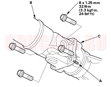
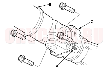
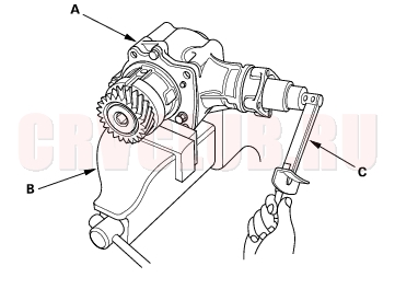
- Make a reference mark (A) across the propeller shaft (B) and the companion flanges (C).
- Separate the propeller shaft from the transfer assembly.
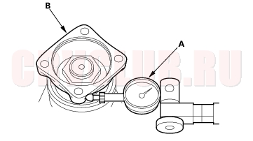
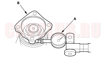
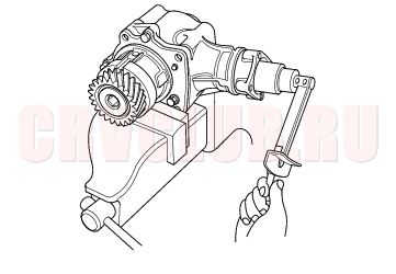
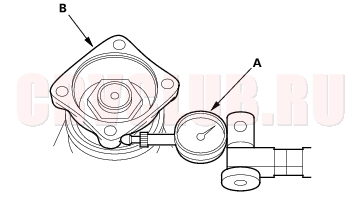
- Set a dial indication (A) on the companion flange (B), then measure the transfer gear backlash.
STANDARD: 0.06 - 0.16 mm (0.002 - 0.006 in.)
- If the measurement is out of specification, remove the transfer assembly (see page 13-64) and inspect the transfer assembly (see page 13-67) .
- Before reinstalling the propeller shaft, check the transfer assembly oil seal for damage and fluid leaks.
- If the seal is leaking, remove the transfer assembly (see page 13-64) , replace the oil seal, and adjust the total starting torque (see step 4 on page 13-67 ). Do not replace the oil seal with the transfer assembly installed on the transmission.
- If the seal is OK, reinstall the propeller shaft.
Transfer Removal13-64
NOTE: Make sure the lifts, jacks, and safety stands are placed properly (see page 01-7) .
- Raise the front of the vehicle, and support it with safety stands (see section 01) .
- Set the parking brake, and block both rear wheels securely.
- Drain the manual transmission fluid. Reinstall the drain plug with a new sealing washer (see page 13-4) .
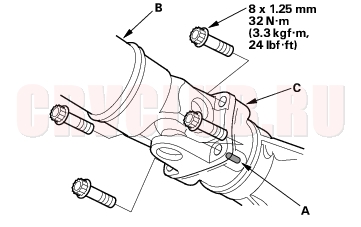
- Make reference marks (A) across the propeller shaft (B) and the companion flanges (C).
- Separate the propeller shaft from the transfer assembly.
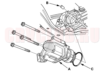
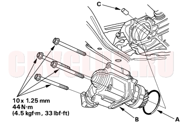
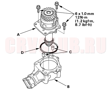
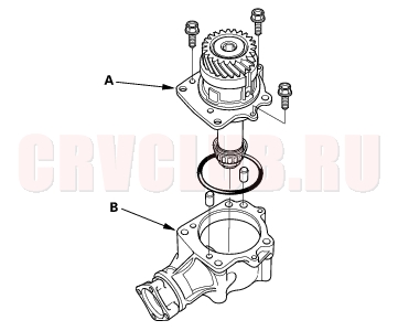
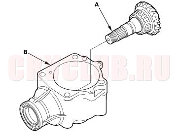
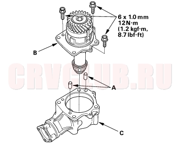
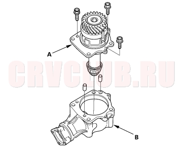
- Remove the transfer (A), dowel pin (B) and O-ring (C).
Transfer Installation13-64
While installing the transfer assembly on the transmission, do not allow dust or other foreign particles to enter the transmission. Be careful not to damage the clutch housing with transfer driven gear.
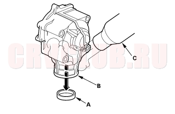
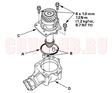
- Install a new O-ring (A) on the transfer (B), then install the dowel pin (C) on the transmission.
- Apply MTF to the transfer driven gear and transmission contact area, then install the transfer to the transmission.
- Install the propeller shaft to the transfer assembly by aligning the reference marks.
- Refill the transmission with MTF (see page 13-4) .
- Start the engine, and run it to normal operating temperature (the radiator fan comes on). Turn the engine off, and check fluid level.
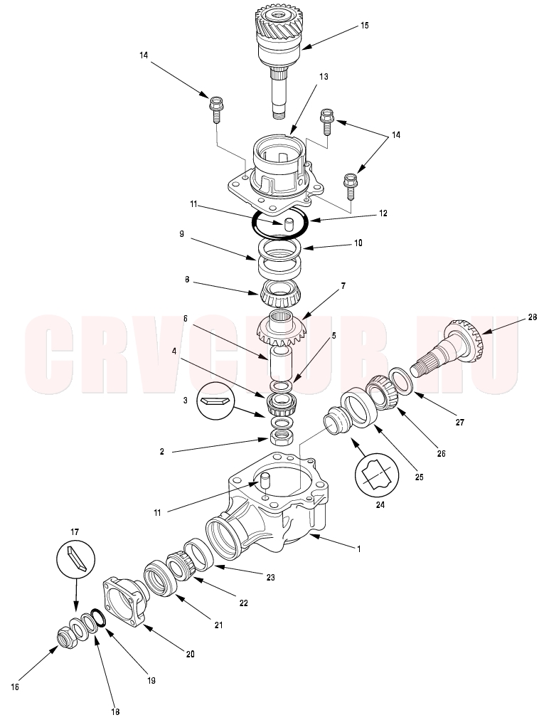
Transfer Overhaul13-65
Exploded View
Exploded View (cont'd)
Transfer Inspection13-67
Transfer Gear (Hypoid gear) Backlash Measurement
STANDARD: 0.06 - 0.16 mm (0.002 - 0.006 in.)
Total Starting Torque Measurement
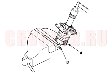
- Rotate the companion flange several times to seat the tapered roller bearing.
- Measure the starting torque (companion flange side) using a torque wrench.
- NOTE: To prevent damage to the transfer housing, always use soft jaws or equivalent materials between the transfer housing and the vise.
STANDARD:
2.24 - 3.71 N·m
(22.0 - 36.4 kgf·cm, 19.1 - 31.6 lbf·in.)
Transfer Drive Gear Tooth Contact Inspection
- Remove the transfer from the vise.
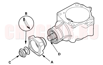
- Remove the transfer holder assembly (A) from the transfer housing (B), then remove the dowel pin (C) and O-ring (D).
- Apply Prussian Blue to the transfer drive gear teeth lightly and evenly.
- Install the transfer holder assembly to the transfer housing, then tighten the bolts.
- Rotate the companion flange in both directions until the transfer gear rotates one full turn in both directions.
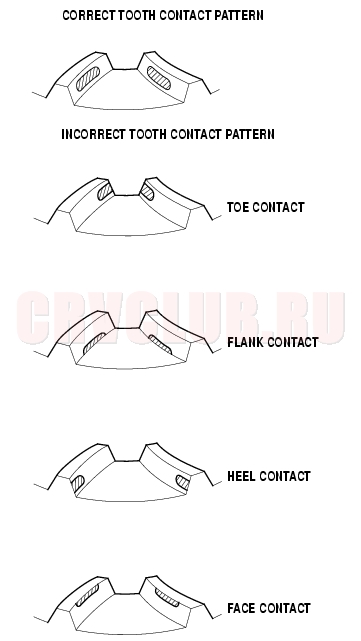
- Check the transfer gear tooth contact pattern.
- If the measurements or the tooth contact pattern are not within the standard, disassemble the transfer assembly, replace worn or damaged parts, and reassemble it.
Transfer Disassembly13-68
Special Tools Required
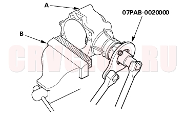
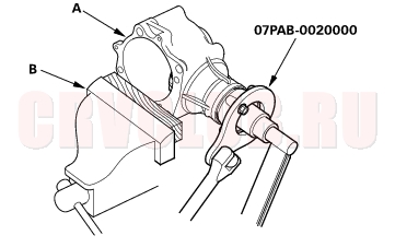
Companion Flange Holder 07PAB-0020000
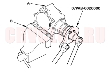
- Remove the transfer holder assembly (A) from the transfer housing (B).
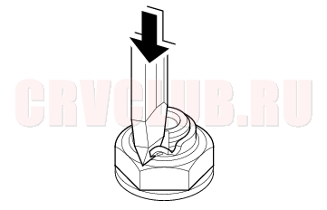
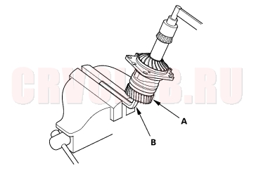
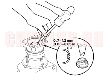
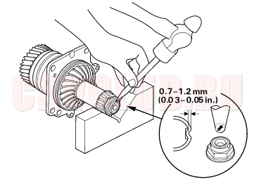
- Cut the lock tabs of the locknut using a chisel. Keep all of the chiseled particles out of the transfer driven gear.
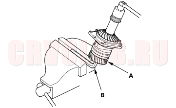
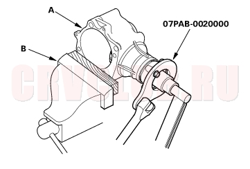
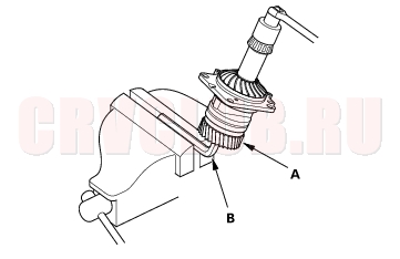
- Secure the transfer housing (A) in a bench vise (B) with soft jaws.
- NOTE: To prevent damage to the transfer housing, always use soft jaws or equivalent materials between the transfer housing and the vise.
- Install the special tool on the companion flange, then loosen the transfer driven gear shaft locknut.
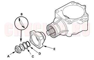
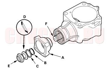
- Remove the transfer driven gear locknut (A), conical spring washer (B), back-up ring (C), O-ring (D) and companion flange (E).
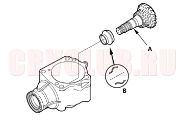
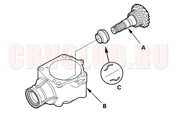
- Remove the transfer driven gear (A), then remove the transfer spacer (B) from the transfer driven gear.
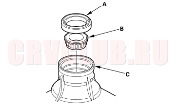
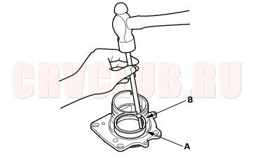
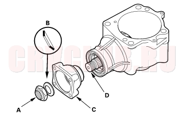
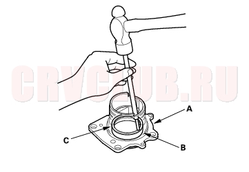
- Remove the oil seal (A) and the tapered roller bearing (B) from the transfer housing (C).
Transfer Holder Disassembly13-70
- Cut the lock tabs of the locknut using a chisel. Keep all of the chiseled particles out of the transfer shaft.
- Hold the transfer shaft (A) with a 14 mm Allen wrench (B) clamped in a bench vise, then loosen the locknut.
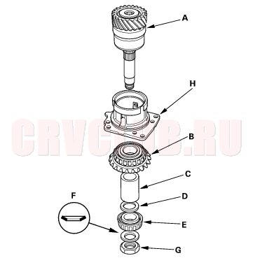
- Remove the locknut (A), conical spring washer (B), tapered roller bearing (C), 25 mm thrust shim (D), transfer shaft collar (E), transfer drive gear (F), and transfer shaft assembly (G) from the transfer holder (H).
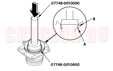
Transfer Holder Tapered Roller Bearing Outer Race Replacement13-71
Special Tools Required
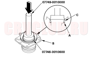
Attachment, 72 x 75 mm 07746-0010600 Driver 07749-0010000 NOTE: Coat all parts with MTF during reassembly.
- Remove the tapered roller bearing outer race (A) and 76 mm thrust shim (B) from the transfer holder.
- Install the 76 mm thrust shim (A) in the transfer holder.
- Install the tapered roller bearing outer race (B) using the special tools and a press.
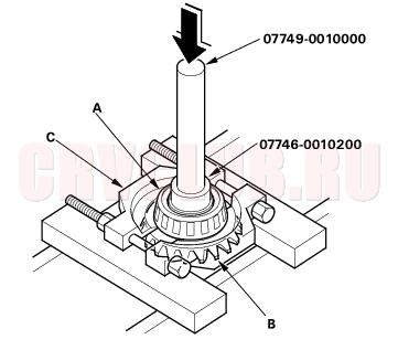
Transfer Drive Gear Bearing Replacement13-71
Special Tools Required
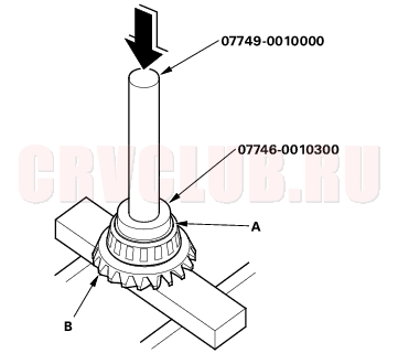
Attachment, 37 x 40 mm 07746-0010200 Attachment, 42 x 47 mm 07746-0010300 Driver 07749-0010000 NOTE: Coat all parts with MTF during reassembly.
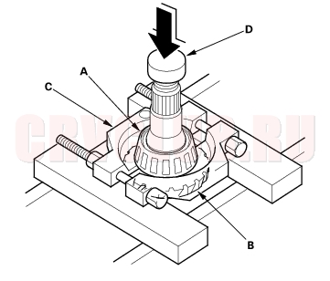
- Remove the tapered roller bearing (A) from the transfer drive gear (B) using a commercially available bearing separator (C), the special tools and a press.
- Install the new tapered roller bearing (A) in the transfer drive gear (B) using the special tools and a press.
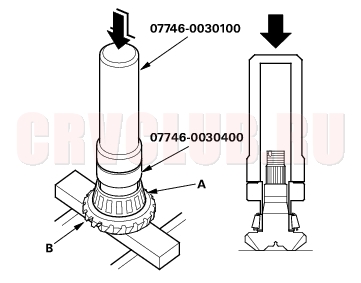
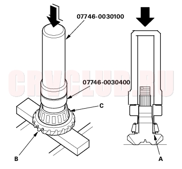
Transfer Driven Gear Bearing Replacement13-72
Special Tools Required
Driver, 40 mm I.D 07746-0030100 Attachment, 35 mm I.D 07746-0030400 NOTE: Coat all parts with MTF during reassembly.
- Remove the tapered roller bearing (A) from the transfer driven gear (B) using a commercially available bearing separator (C), an adapter (D), and a press.
- Install the new tapered roller bearing (A) on the transfer driven gear (B) using the special tools and a press.
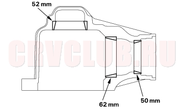
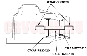
Transfer Housing Bearing Outer Race Replacement13-72
Special Tools Required
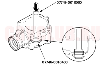
Installer shaft, 14 x 165 mm 07JAF-SJ80110 Installer nut, 14 mm 07JAF-SJ80120 Bearing installer attachment 07KAF-PS30120 Bearing installer attachment 07LAF-PZ70110 Attachment, 52 x 55 mm 07746-0010400 Driver 07749-0010000
Coat all parts with MTF during reassembly. Replace the tapered roller bearing and the bearing outer race as a set if either part is replaced.
- Remove the tapered roller bearing outer race (A) from transfer housing (B) by heating the cover to almost 212°F (100°C) using a heat gun (C). Do not heat the cover over 212°F (100°C).
- Install the 52 mm tapered roller bearing outer race using the special tools.
- Install the 62 mm tapered roller bearing outer race and 50 mm tapered roller bearing outer race using the special tools.
Transfer Reassembly13-73
Special Tools Required
Oil seal driver attachment 07JAD-PH80101 Companion flange holder 07PAB-0020000 Attachment, 72 x 75 mm 07746-0010600 Driver, 40 mm I.D 07746-0030100 Attachment, 35 mm I.D 07746-0030400 Driver 07749-0010000 Note these items during reassembly:
While reassembling the transfer assembly:
Check and adjust the transfer gear tooth contact. Measure and adjust the transfer gear backlash. Check and adjust the tapered roller bearing starting torque. Cost all parts with MTF during reassembly. Replace the tapered roller bearing and the bearing outer race as a set if either part is replaced. Replace the transfer drive gear and the transfer driven gear shaft as a set if either part is replaced. Outline of Assembly
- Select the 35 mm thrust shim.
- Perform this procedure if the transfer driven gear shaft or the tapered roller bearing on the transfer driven gear shaft is replaced.
- Preassemble the parts to check and adjust transfer gear backlash and transfer gear tooth contact.
- Disassemble the parts, then assemble the transfer driven gear shaft and its related parts.
- Measure and adjust the starting torque of the transfer driven gear shaft tapered roller bearing.
- Assemble the transfer shaft and its related parts.
- Measure and adjust the total starting torque.
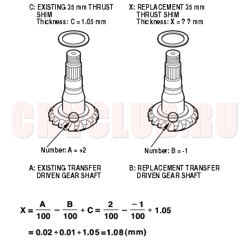
35 mm Thrust Shim Selection
- Select the 35 mm thrust shim if the transfer driven gear shaft or the tapered roller bearing on the transfer driven gear shaft is replaced.
- Calculate the thickness of the 35 mm thrust shim using the formula below.
A: Number on the existing transfer driven gear shaft
B: Number on the replacement transfer driven gear shaft.
C: Thickness of the existing 35 mm thrust shim
X: Thickness needed for the replacement 35 mm trust shim.
NOTE: The number on the transfer driven gear shaft is shown in 1/100 mm.
Select 35 mm thrust shim thickness of 1.08 mm (0.043 in.). If the tapered roller bearing on the transfer driven gear shaft is replaced. Measure the thickness of the replacement bearing and the existing bearing, and calculate the difference of the bearing thickness. Adjust the thickness of the existing 35 mm thrust shim by the amount of difference in bearing thickness, and select the replacement 35 mm thrust shim. Do not use more than one 35 mm thrust shim to adjust the transfer gear backlash.
Transfer Gear Backlash Inspection and Transfer Gear Tooth Contact Inspection
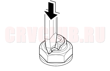
- Install the 35 mm thrust shim (A) on the transfer driven gear (B), then install the tapered roller bearing (C) using the special tools and a press.
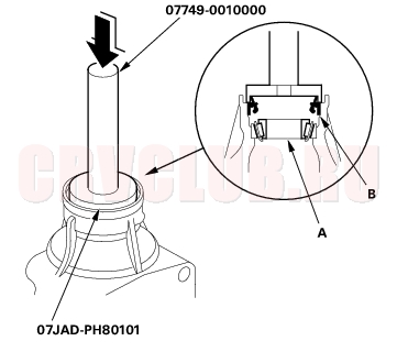
- Install the bearing outer race, then the tapered bearing (A) on the companion flange side of the transfer housing.
- Install the new oil seal (B) on the transfer housing using the special tools.
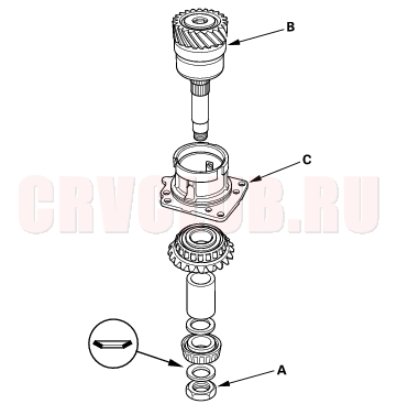
- Install the transfer driven gear (A) in the transfer housing (B). Do not install the transfer spacer on the transfer driven gear shaft in this step.
- Install the companion flange (A), conical spring washer (B) and locknut (C) on the transfer driven gear (D). Do not install the O-ring and the back-up ring on the transfer gear shaft in this step.
- Secure the transfer housing (A) in a bench vise (B) with soft jaws, then install the special tool on the companion flange.
- NOTE: To prevent damage to the transfer housing, always use soft jaws or equivalent materials between the transfer housing and the vise.
- Tighten the locknut while measuring the starting torque so the starting torque is within 1.08-1.47 N·m (11.0 - 15.0 kgf·cm, 9.55 - 13.0 lbf·in.).
- NOTE:
- Coat the threads of the locknut, and the shaft with MTF before installing the locknut.
- Do not stake the locknut in this step.
STARTING TORQUE:
1.08 - 1.47 N·m
(11.0 - 15.0 kgf·cm, 9.55 - 13.0 lbf·in.)
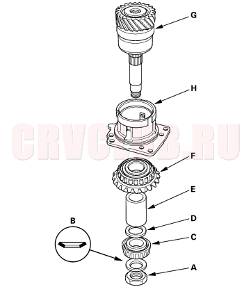
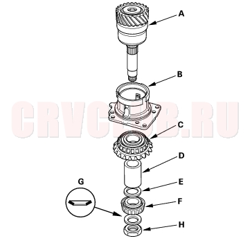
- Install the transfer shaft assembly (A) in the transfer holder (B), then install the transfer drive gear (C), transfer collar (D), 25 mm thrust shim (E), tapered roller bearing (F), conical spring washer (G), and locknut (H) on the transfer shaft assembly.
- NOTE:
- Coat the threads of the locknut, and the shaft with MTF before installing the locknut.
- Do not stake the locknut in this step.
- Hold the transfer shaft (A) with a 14 mm Allen wrench (B) clamped in a bench vise, and tighten the locknut.
- NOTE: Do not stake the locknut in this step.
TORQUE: 118 N·m (12.0 kgf·m, 86.8 lbf·ft)
- Apply Prussian Blue to both sides of the transfer drive gear teeth lightly and evenly.
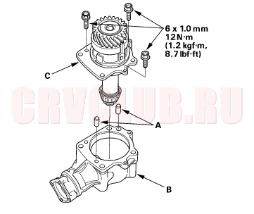
- Install the dowel pin (A) and transfer holder assembly (B) to the transfer housing (C).
- NOTE: Temporarily install the transfer holder assembly without the O-ring.
- Rotate the companion flange several times to seat the tapered roller bearing.
- Set a dial indicator (A) on the companion flange (B), then measure the transfer gear backlash.
STANDARD: 0.06 - 0.16 mm (0.002 - 0.006 in.)
- If the transfer gear tooth contact is incorrect, adjust the transfer gear tooth contact with a 35 mm or 25 mm thrust shim. If the gear tooth contact is correct, go to step 17.
- NOTE:
- To select a 35 mm thrust shim, refer to page 13-74 .
- Do not use more than one 35 mm shim to adjust the transfer gear tooth contact.
- To select the 25 mm thrust shim, refer to page 13-78 .
- Do not use more than one 25 mm shim to adjust the transfer gear tooth contact.
- Toe Contact
- Use a thicker 35 mm thrust shim to move the transfer driven gear shaft toward the transfer drive gear. Because this movement causes the transfer gear backlash to change, move the transfer drive gear away from the transfer driven gear shaft to adjust the transfer gear backlash as follows:
- Increase the thickness of the 25 mm thrust shim.
- Reduce the thickness of the 76 mm thrust shim by the amount of increased thickness of the 25 mm thrust shim.
Flank Contact Use a thinner thrust shim to move the transfer drive gear toward the transfer driven gear shaft. Flank contact must be adjusted within the limits of the transfer gear backlash. If the backlash exceeds the limits, adjust as described under Heel Contact. Heel Contact Use a thinner 35 mm thrust shim to move the transfer driven gear shaft away from the transfer drive gear. Because this movement causes the transfer gear backlash to change, move the transfer drive gear toward the transfer driven gear shaft to adjust the transfer gear backlash as follows: - Reduce the thickness of the 25 mm thrust shim.
- Increase the thickness of the 76 mm thrust shim by the amount of reduced thickness of the 25 mm thrust shim.
Face Contact Use a thicker thrust shim to move the transfer drive gear away from the transfer driven gear shaft. Face contact must be adjusted within the limits of the transfer gear backlash. If the backlash exceeds the limits, adjust as described under Toe Contact.
- Remove the transfer holder assembly (A) from the transfer housing (B).
- Secure the transfer housing (A) in a bench vise (B) with soft jaws.
- NOTE: To prevent damage to the transfer housing, always use soft jaws or equivalent materials between the transfer housing and the vise.
- Install the special tool on the companion flange, then loosen the locknut.
- Remove the locknut (A), conical spring washer (B) and companion flange (C) from the transfer driven gear (D).
- Remove the transfer driven gear (A) from the transfer housing (B).
- Install the new transfer spacer (C) on the transfer driven gear (A), then install them in the transfer housing (B).
- Install the companion flange (A), O-ring (B), back-up ring (C), conical spring washer (D) and locknut (E) on the transfer driven gear (F).
- NOTE:
- Coat the threads of the locknut, O-ring and transfer shaft with MTF before installing the locknut.
- Install the conical spring washer in the direction shown.
- Secure the transfer housing (A) in a bench vise (B) with soft jaws.
- NOTE: To prevent damage to the transfer housing, always use soft jaws or equivalent materials between the transfer housing and the vise.
- Install the special tool on the companion flange, then tighten the transfer driven gear shaft locknut while measuring the starting torque of the transfer driven gear shaft.
STARTING TORQUE:
1.08 - 1.47 N·m
(11.0 - 15.0 kgf·cm, 9.55 - 13.0 lbf·in)
TIGHTENING TORQUE:
132 - 260 N·m
(13.5 - 26.5 kgf·m, 97.6 - 192 lbf·ft)
NOTE: Rotate the companion flange several times to seat the tapered roller bearing, then measure the starting torque. If the starting torque exceeds 1.47 N·m (15.0 kgf·cm, 13.0 lbf·in.), replace the transfer spacer and reassemble the parts. Do not adjust the torque with the locknut loose. If the tightening torque exceeds 260 N·m (26.5 kgf·m, 192 lbf·ft), replace the transfer spacer and reassemble the parts. Write down the measurement of the starting torque: it is used to measure the total starting torque.
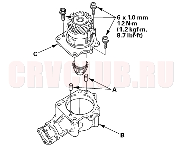
- Install the dowel pin (A) to the transfer housing (B), then install the transfer holder assembly (C).
- NOTE: Temporarily install the transfer holder assembly without the O-ring.
- Secure the transfer housing (A) in a bench vise (B) with soft jaws, then rotate the companion flange several times to fit the tapered roller bearing.
- NOTE: To prevent damage to the transfer housing, always use soft jaws or equivalent materials between the transfer housing and the vise.
- Measure the total starting torque using the torque wrench (C).
TOTAL STARTING TORQUE:
1.70 - 2.08 N·m (17.3 - 21.2 kgf·cm, 15.0 - 18.4 lbf·in.) + Transfer Driven Gear Shaft Starting Torque Value (wrote down in step 25).
- Remove the transfer holder assembly from the transfer housing.
- If the measurement is not within the specification, go to step 32.
If the measurement is within the specification, go to step 43.
- Hold the transfer shaft (A) with a 14 mm Allen wrench (B) clamped in a bench vise then loosen the locknut.
- Remove the locknut (A) and transfer shaft assembly (B) from the transfer holder (C).
- Remove the tapered roller bearing outer race (A) and 76 mm thrust shim (B) from the transfer holder (C).
- Measure the thickness of the removed 76 mm thrust shim, and select a new 76 mm shim.
- Install the 76 mm thrust shim (A) in the transfer holder (B).
- Install the tapered roller bearing outer race (C) using the special tool and a press.
- Install the transfer shaft assembly (A), transfer drive gear (B), transfer shaft collar (C), 25 mm thrust shim (D), tapered roller bearing (E), conical spring washer (F) and locknut (G) in the transfer holder (H).
- Hold the transfer shaft (A) with a 14 mm Allen wrench (B) clamped in a bench vise then tighten the locknut.
- NOTE: Do not stake the locknut in this step.
TIGHTENING TORQUE:
118 N·m (12.0 kgf·m, 86.8 lbf·ft)
- Install the dowel pin (A) to the transfer housing (B), then install the transfer holder assembly (C).
- Recheck and make sure the total starting torque is within the specification.
|
M/T - M/T Differential13-1
Transfer Assembly13-63 |