A/T Gear Position Indicator14-165
|
A/T
A/T Gear Position Indicator14-165 |
A/T Gear Position Indicator14-165
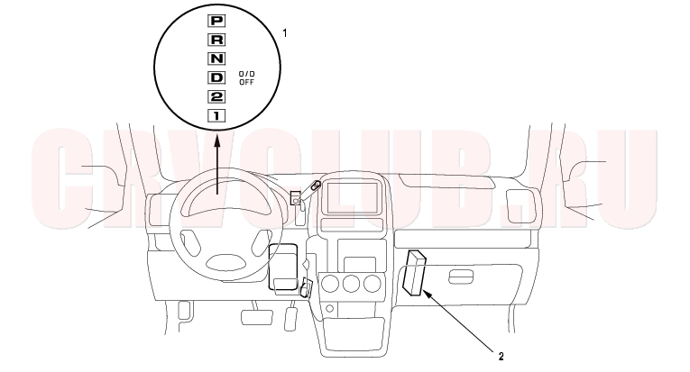
Component Location Index
NOTE: The illustration shows the LHD model; RHD is symmetrical.
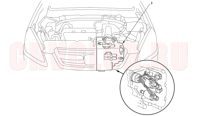
NOTE: The illustration shows the LHD model; RHD is similar.
Indicator Input test, page 14-167 ; Indicator Bulb Replacement, page 14-171 Test, page 14-168 ; Replacement, page 14-169
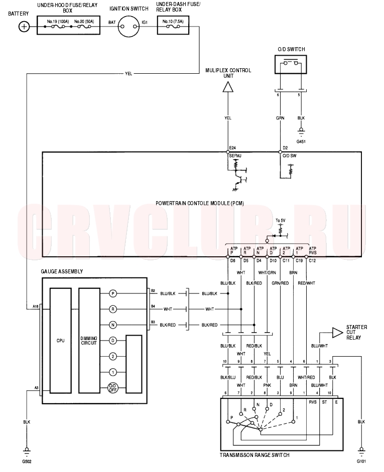
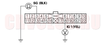
Circuit Diagram14-165
Indicator Input Test14-167
- If the MIL has been reported, check for a DTC, and repair the system as indicated by DTC.
- If the MIL does not come on, and the A/T gear position indicator [P], [N], or [R] does not come on, remove the gauge assembly from the dashboard, then disconnect gauge assembly connector A (22P) and B (22P).
- Inspect the connectors and connector terminals to be sure they are making good contact.
- If the terminals are bent, loose, or corroded, repair them as necessary, and recheck the system.
- Turn the ignition switch ON (II).
- Shift to [P] position, and check for continuity between B2 terminal (BLU/BLK) and ground.
There should be continuity in [P] position and no continuity in any other shift lever position. If the test results are different, check for a faulty transmission range switch or an open in the wire.
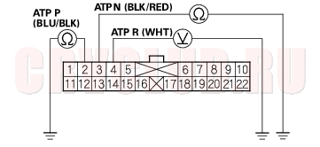
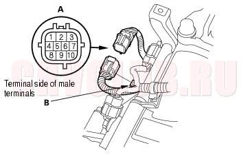
- NOTE: The illustration shows example of connector terminal arrangement; connector terminal arrangement varies with models.
- Shift to [R] position, and check for voltage between B4 terminal (WHT) and ground.
There should be 0 V in [R] position. There should be battery voltage in any other shift lever position. If the test results are different, check for a faulty transmission range switch or an open in the wire.
- Shift to [N] position, and check for continuity between B3 terminal (BLK/RED) and ground.
There should be continuity in [N] position and no continuity in any other shift lever position. If the test results are different, check for faulty transmission range switch or an open in the wire.
- Check for voltage A18 terminal (YEL) and ground with the ignition switch ON (II).
There should be battery voltage. If the test result is different, check for a blown No. 10 (7.5A) fuse in the under-dash fuse/relay box or an open in the wire.
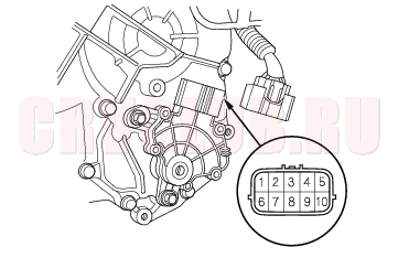
- NOTE: The illustration shows example of connector terminal arrangement; connector terminal arrangement varies with models.
- Turn the ignition switch OFF, and check for continuity between A3 terminal (BLK) and ground under all conditions.
There should be continuity. If the test result is different, check for a poor ground (G502) or an open in the wire.
- If a input test prove OK, but the indicator is faulty, replace the printed circuit board.
Transmission Range Switch Test14-168
- Remove the transmission range switch harness connector (A) from the connector bracket (B), then disconnect the connector.
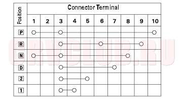
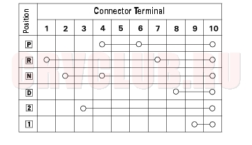
Connector Terminal Specification
- Check for continuity between terminals at the harness connector. There should be continuity between the terminals in the following table for each switch position.
- If there is no continuity between any terminals, remove the transmission range switch cover, and disconnect the connect at the switch.
Connector Terminal Specification
- Check for continuity between terminals at the switch connector. There should be continuity between the terminals in the following table for each switch position.
- If there is no continuity between any terminals, check the transmission range switch installation. If the transmission range switch installation is OK, replace the switch.
If the transmission range switch continuity check was OK, replace the faulty transmission range switch harness.
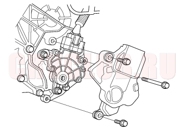
Transmission Range Switch Replacement14-169
- Raise the vehicle, and make sure it is securely supported.
- Shift to [N] position.
- Remove the transmission range switch cover.
- Disconnect the transmission range switch connector.
- Remove the old transmission range switch, and install the new switch.
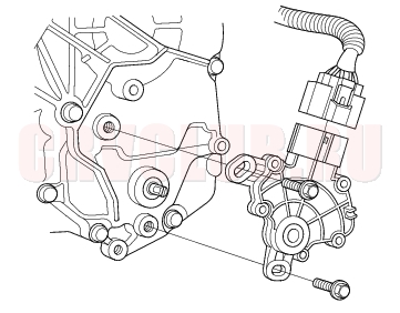
- Make sure that the control shaft is in [N] position. If necessary, move the shift lever to [N] position.
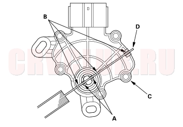
- Align the cutout (A) on the rotary-frame with the neutral positioning cutouts (B) on the transmission range switch (C), then put a 2.0 mm (0.08 in.) feeler gauge blade (D) in the cutouts to hold it in the [N] position.
- NOTE: Be sure to use a 2.0 mm (0.08 in.) blade or equivalent to hold the switch in the [N] position.
Transmission Range Switch Replacement (cont'd)14-170
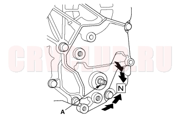
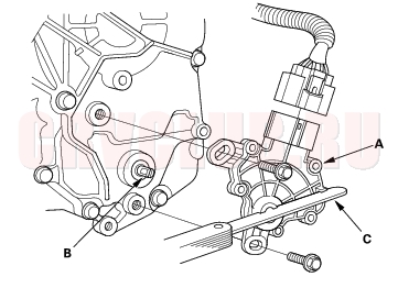
- Install the transmission range switch (A) gently on the control shaft (B) with holding the [N] position with the 2.0 mm (0.08 in.) blade (C).
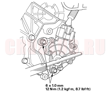
- Tighten the bolts on the transmission range switch while you continue to hold the [N] position. Do not move the transmission range switch when tightening the bolts. Remove the feeler gauge.
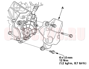
- Connect the connector securely, then install the transmission range switch cover (A).
- Turn the ignition switch ON (II). Move the shift lever through all gear positions, and check the transmission range switch synchronization with the A/T gear position indicator.
- Check that the engine can start in [P] and [N] positions, and cannot start in any other shift lever position.
- Check that the back-up lights come on when the shift lever is in [R] position.
- Allow the wheels to rotate freely, then start the engine, and check the shift lever operation.
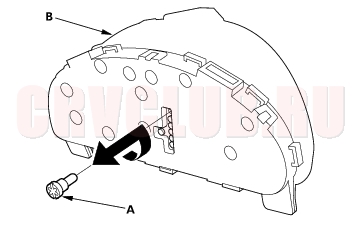
Indicator Bulb Replacement14-171
|
A/T
A/T Gear Position Indicator14-165 |