A/T Interlock System14-172
|
A/T
A/T Interlock System14-172 |
A/T Interlock System14-172
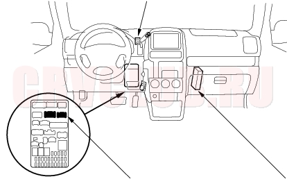
Component Location Index
LHD Model:
STEERING LOCK ASSEMBLY KEY INTERLOCK SOLENOID
System circuit troubleshooting,
page 14-179 Test, page 14-181Test/Replacement, page 14-187 SHIFT LOCK SOLENOID System circuit troubleshooting, page 14-175 Test/Replacement, page 14-182
INTERLOCK CONTROL UNIT (KS) MODEL
Input test, page 14-180
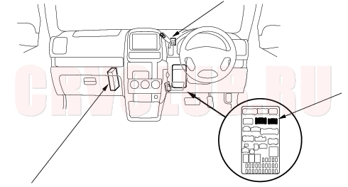
RHD Model:
STEERING LOCK ASSEMBLY
System circuit troubleshooting, page 14-179 Test, page 14-181
KEY INTERLOCK SOLENOIDTest/Replacement, page 14-187 SHIFT LOCK SOLENOID System circuit troubleshooting, page 14-175 Test/Replacement, page 14-182
No. 10 CONNECTOR (13P)
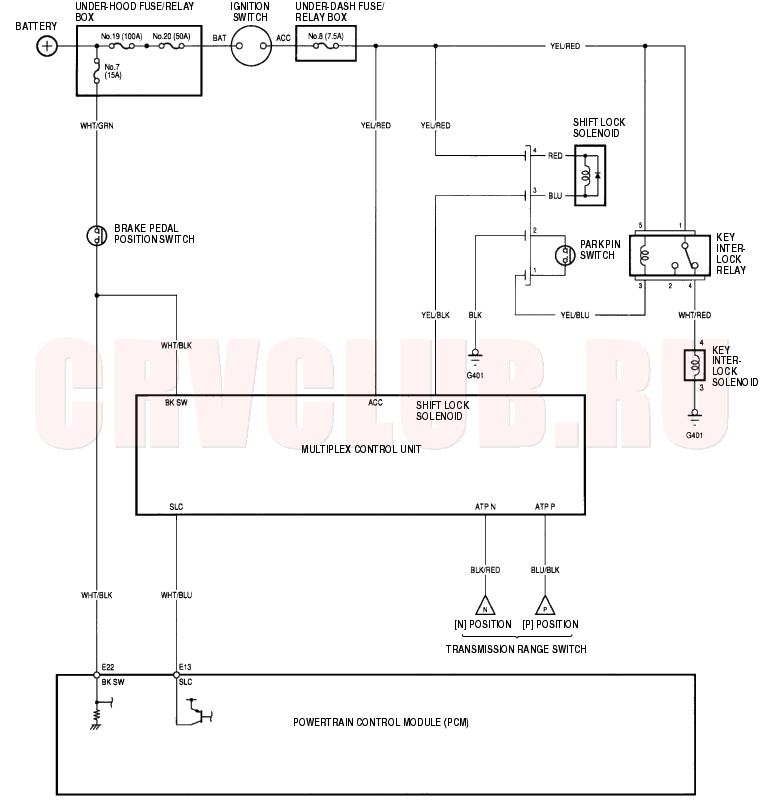
Circuit Diagram14-173
Except KS Model
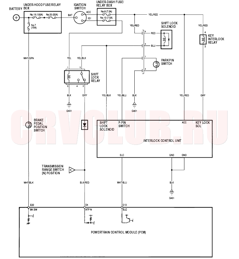
Circuit Diagram (cont'd)14-174
KS Model
Shift Lock System Circuit Troubleshooting14-175
Are the brake lights ON?
Yes : Go to step 2.
No : Repair faulty brake light circuit.

- Turn the ignition switch ON (II).
- With the accelerator pedal released, press the brake pedal.
- Measure the voltage between PCM connector terminal E13 and body ground.
Is there battery voltage?
Yes : Check for an open in the wire between PCM connector terminal E13 and the multiplex control unit (except KS model) or interlock control unit (KS model). If the wire is OK, check for a loose terminal fit in the multiplex control unit (except KS model) or interlock control unit (KS model) connectors. If necessary, substitute a known-good multiplex control unit (except KS model) or interlock control unit (KS model) and recheck.
No : Go to step 5.
- Turn the ignition switch OFF.
- Disconnect the battery negative terminal.
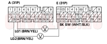
- Disconnect PCM connectors A (31P) and E (31P).
- Reconnect the battery negative terminal.
- Press the brake pedal, and measure the voltage between PCM connector terminals E22 and A23 or A24.
Is there battery voltage?
Yes : Release the brake pedal, and go to step 10 except for KS model; for KS model, go to step 12.
No : Repair open in the wire between PCM connector terminal E22 and the brake pedal position switch.
Shift Lock System Circuit Troubleshooting (cont'd)14-176
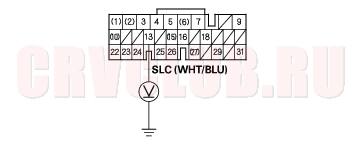
- Remove the under-dash fuse/relay box, and disconnect the No. 10 connector (13P) from the fuse/relay box.
- Measure the voltage between the No. 3 terminal of the No. 10 connector (13P) and body ground while pressing the brake pedal.
Is there battery voltage?
Yes : Release the brake pedal, and go to step 12.
No : Repair open or short in the wire between the multiplex control unit and the brake pedal position switch via the No. 3 terminal of the No. 10 connector (13P).
- Disconnect the battery negative terminal.
- Connect PCM connectors A (31P) and E (31P).
- Connect the No. 10 connector (13P) except for KS model.
- Reconnect the battery negative terminal.
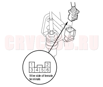
- Disconnect the O/D switch/shift lock solenoid/park pin switch connector (see page 14-152) .
- Turn the ignition switch ON (II).
- With the accelerator pedal released, press the brake pedal, and measure the voltage between the No. 4 terminal of the O/D switch/shift lock solenoid/park pin switch connector and body ground.
Is there battery voltage?
Yes : Go to step 19.
No : Repair open or short in the wire between the O/D switch/shift lock solenoid/park pin switch connector and under-dash fuse/relay box.
14-177
- Measure the voltage between the No. 3 and No. 4 terminals of the O/D switch/shift lock solenoid/park pin switch connector while pressing the brake pedal.
Is there battery voltage?
Yes : Go to step 20.
No : Repair open in the wire between the O/D switch/shift lock solenoid/park pin switch connector and the multiplex control unit (except KS model) or interlock control unit (KS model).
- Connect the battery positive terminal to the No. 4 terminal of the O/D switch/shift lock solenoid/park pin switch connector, and connect the battery negative terminal to the No. 3 terminal. Check that the shift lock solenoid operates.
- NOTE: Do not connect the battery positive terminal to the No. 3 terminal or you will damage the diode inside the shift lock solenoid.
Does the shift lock solenoid operate properly?
Yes : Check that the shift lock mechanism works properly. If the mechanism does not work, repair or replace the shift lever assembly. If necessary, substitute a known-good multiplex control unit (except KS model) or interlock control unit (KS model) and recheck.
No : Replace the shift lock solenoid.
Reverse Lock System Circuit Troubleshooting14-178
Is either DTC indicated?
Yes : Perform the Troubleshooting Flowchart for the indicated Code(s).
No : Go to step 2.
- Turn the ignition switch OFF.
- Shift the shift lever to the [P] position while pushing the shift lock release.
- Turn the ignition switch ON (II).
- Press the brake pedal and release the accelerator, shift the shift lever out of the [P] position, and check that the shift lock solenoid operates.
Does the shift lock solenoid operate properly?
Yes : Check the reverse lock mechanism. If the mechanism does not work, repair or replace the shift lever assembly.
No : Perform the Shift Lock System Circuit Troubleshooting (see page 14-175).
Key Interlock System Circuit Troubleshooting14-179
- Disconnect the steering lock assembly connector.
- Check if the ignition key can be turned to LOCK (0) position, and removed from the key cylinder.
Is the ignition key able to turn to LOCK (0) position, and remove from key cylinder?
Yes : Go to step 3.
No : Replace the ignition key cylinder/steering lock assembly.
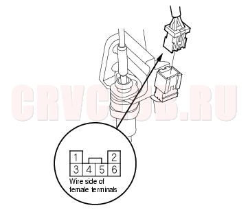
- Disconnect the O/D switchshift lock solenoid/park pin switch connector (see page 14-187) .
- Check for continuity between the No. 1 and No. 2 terminals of the O/D switch/shift lock solenoid/park pin switch connector while the shift lever is in [P] position, and when shift lever out of [P].
Is there continuity while the shift lever is in [P] position, and no continuity when the shift lever out of [P]?
Yes : Go to step 5.
No : Faulty park switch, replace it.
- Connect the steering lock assembly connector.
- Turn the ignition switch to ACC (I).
- Measure the voltage between the No. 1 terminal of the O/D switch/shift lock solenoid/park pin switch connector and body ground.
Is there voltage?
Yes : Repair open in the wire between the park pin switch and ground (G401), or repair poor ground (G401).
No : Except KS model: Check for an open in the wire between the park pin switch connector and the under-dash fuse/relay box via the key interlock relay. If the wire is OK, replace the key interlock relay, and recheck.
KS model: Check for an open in the wire between the park pin switch connector and the interlock control unit. If the wire is OK, check for loose terminal fit in the interlock control unit connector. If necessary, substitute a known-good interlock control unit and recheck.
Interlock Control Unit Input Test14-180
KS Model
- Disconnect interlock control unit connector.
- Inspect the connector and connector terminals to be sure they are making good contact.
- If the terminals are bent, loose, or corroded, repair them as necessary, and recheck the system.
- Turn the ignition switch ACC (I).
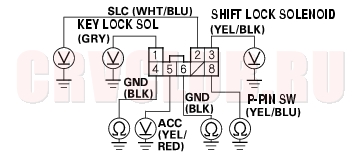
- Measure the voltage between interlock control unit connector terminal No. 1 and body ground.
There should be voltage. If there is no voltage, check for a blown No. 8 (7.5A) fuse in the under-dash fuse/relay box, a key lock solenoid defect, or an open or a short in the wire.
- Measure the voltage between interlock control unit connector terminal No. 3 and body ground.
There should be voltage. If there is no voltage, check for a blown No. 8 (7.5A) fuse, a shift lock solenoid defect, or an open or a short in the wire.
- Measure the voltage between interlock control unit connector terminal No. 5 and body ground.
There should be battery voltage. If there is no voltage, check for a blown No. 8 (7.5A) fuse or an open or a short in the wire.
- Turn the ignition switch ON (II), and shift the shift lever in [P] position.
- Press the brake pedal, release the accelerator pedal, and measure the voltage between interlock control unit connector terminal No. 2 and body ground. There should be battery voltage. If there is no voltage, check for an open or short in the wire.
- Check for continuity between interlock control unit connector terminal No. 8 and body ground while shift lever in [P] position, and when shift lever out of [P]. There should be continuity while shift lever in [P] position, and there should be no continuity when shift lever out of [P]. If the test results are different, a park pin switch defect, and check for an open in the wire.
- Check for continuity between interlock control unit connector terminals No. 4 and body ground, and between No. 6 and body ground. There should be continuity to ground under all conditions. If there is no continuity, check for an open in the wires, or poor ground (G401).
Key Interlock Solenoid Test14-181
- Remove the driver's dashboard lower cover and lower steering column cover.
- Disconnect steering lock assembly connector.
- Insert the ignition key in the key cylinder, then turn the ignition key to ACC (I).
- Connect the battery positive terminal to steering lock assembly connector terminal No. 4, and connect the battery negative terminal to No. 3 terminal. Make sure that the ignition key cannot be turned to LOCK (0) position. Release the battery terminals, and make sure that the key can be turned to LOCK (0) position and removed from cylinder.
- If the key interlock solenoid works improperly, replace the ignition key cylinder/steering lock assembly.
Shift Lock Solenoid Test/Replacement14-182
- Remove the ash tray, front console box, heater control panel (see page 20-91) , driver's dashboard lower cover (see page 20-88) , and dashboard gauge assembly cover (see page 20-87) .
- Disconnect the O/D switch/shift lock solenoid/park pin switch connector.
- NOTE: The illustration shows LHD model; RHD is symmetrical.
- Connect the battery positive terminal to the No. 4 terminal of the O/D switch/shift lock solenoid/park pin switch connector, and connect the battery negative terminal to the No. 3 terminal.
- NOTE: Do not connect the battery negative terminal to the No. 3 terminal or you will damage the diode inside the solenoid.
- Check that the shift lever can be moved from [P] position. Release the battery terminals, move the shift lever back to the [P], and make sure it locks. If the shift lock solenoid works properly, connect the connector and install the removed parts.
If the shift lock solenoid is faulty, go to step 5 for replacement.
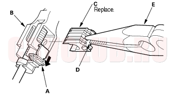
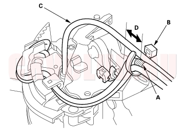
- Shift the shift lever to [R] position.
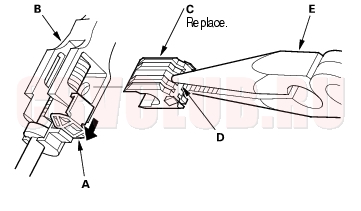
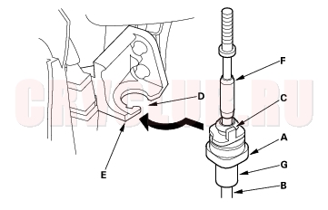
- Slide the lock tab (A) down on the shift cable end holder (B).
- Remove the shift cable lock (C) with holding at the middle (D) of it using needle-nose pliers (E) from the shift cable end and shift cabel end holder.
- NOTE: Do not pry the shift cable lock with a screwdriver, it may damage the shift cable end holder.
- Separate the shift cable end from the shift cable end holder.
14-183
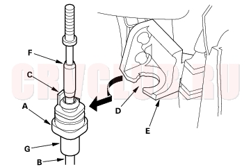
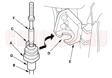
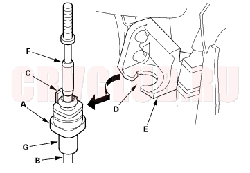
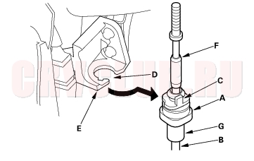
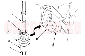
- Rotate the socket holder (A) on the shift cable (B) a quarter turn; the tab (C) on the socket holder will be in the opening (D) of the socket holder bracket (E). Then slide the holder to remove the shift cable from the socket holder bracket.
- NOTE: Do not remove the shift cable by twisting the shift cable guide (F) and damper (G).
LHD Model:
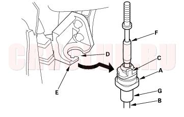
RHD Model:
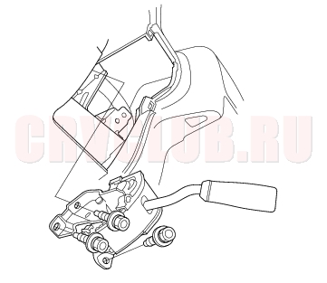
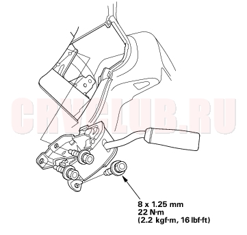
- Remove the shift lever assembly.
- NOTE: The illustration shows LHD model; RHD is symmetrical.
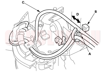
- Remove the harness from the harness clamp on the shift lever bracket base, and remove the harness band from the harness.
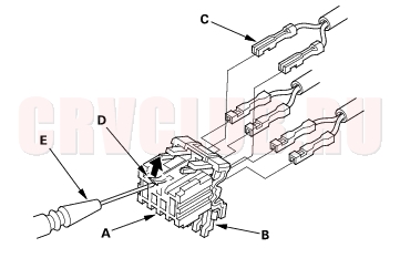
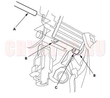
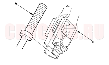
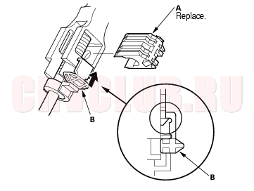
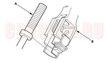
- Pry the lock tabs on the back of the O/D switch/shift lock solenoid/park pin switch connector (A), and remove the back cover (B).
- Remove the terminal (C) from the connector by pushing the lock tab (D) up in the connector using a thin blade screwdriver (E). Remove all six terminals.
Shift Lock Solenoid Test/Replacement (cont'd)14-184
- Remove the shift lever cover.
- Remove the shift lock solenoid.
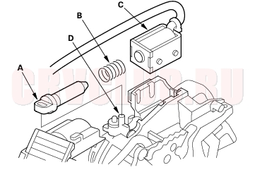
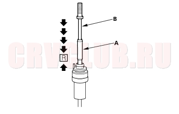
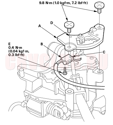
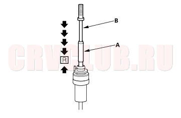
- Install the shift lock solenoid plunger (A) and plunger spring (B) in the new shift lock solenoid (C).
- Install the shift lock solenoid by aligning the joint of the shift lock solenoid plunger with the tip of the shift lock stop (D).
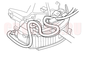
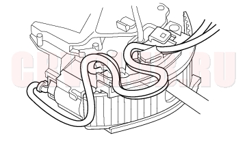
- Route the harnesses, and clamp them as shown.
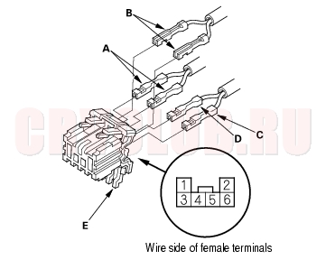
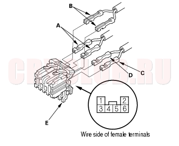
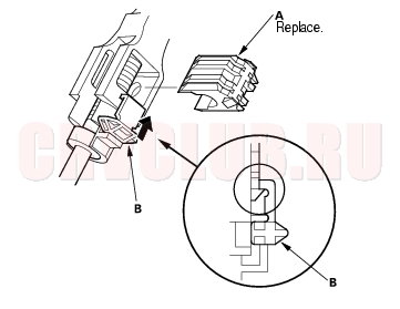
- Install the O/D switch harness terminals (A) in the No. 5 and No. 6 cavities. Both of O/D switch harness terminals can be installed in No. 5 and No. 6 cavities.
- Install the park pin switch harness terminals (B) in the No. 1 and No. 2 cavities. Both of park pin switch harness terminals can be installed in No. 1 and No. 2 cavities.
- Install BLU harness terminal (C) of the shift lock solenoid in the No. 3 cavity, and RED harness terminal (D) in the No. 4 cavity. Make sure that the all six terminals lock securely, then install the back cover (E) locked securely in place.
14-185
- Align the marks (A) on the harnesses, and tie the harness band (B) over the marks. Clamp the O/D switch harness (C) at 15 mm (0.6 in.) (D) from the harness band.
- Install the shift lever cover.
- Install the shift lever assembly.
- NOTE: The illustration shows LHD model; RHD is symmetrical.
- Turn the ignition switch ON (II), and verify that the [R] position indicator comes on.
- If necessary, push the shift cable until it stops, then release it. Pull the shift cable back one step so that the shift cable is in [R]. Do not hold the shift cable guide (A) to adjust the shift cable (B).
- Turn the ignition switch OFF.
- Insert a 6.0 mm (0.24 in.) pin (A) into the positioning holes (B) on the shift lever bracket base through the positioning hole (C) on the shift lever. The shift lever is secured in [R] position.
Shift Lock Solenoid Test/Replacement (cont'd)14-186
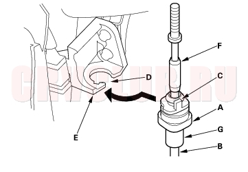
- Rotate the socket holder (A) on the shift cable (B) to face the tab (C) on the holder opposite to the opening (D) in the socket holder bracket (E). Align the holder with the opening in the bracket, then slide the holder into the bracket. Rotate the holder a quarter turn to secure the shift cable. Do not install the shift cable by twisting the shift cable guide (F) and damper (G).
LHD Model:
RHD Model:
- Install the shift cable end (A) in the shift cable end holder (B). Keep the shift cable end and end holder free of grease.
- Install the new shift cable lock (A) to secure the shift cable end and shift cable end holder, then push the lock tab (B) up until it stops to lock the joint.
- Remove the 6.0 mm (0.24 in.) pin that was installed to hold the shift lever.
- Connect the O/D switch/shift lock solenoid/park pin switch connector.
- Move the shift lever to each gear, and verify that the A/T gear position indicator follows the transmission range switch.
- Check that the shift lock solenoid operates.
- Install the dashboard gauge assembly cover (see page 20-87) , driver's dashboard lower cover (see page 20-88) , heater control panel (see page 20-91) , front console box, and ash tray.
Park Pin Switch Test/Replacement14-187
- Remove the ash tray, front console box, heater control panel (see page 20-91) , driver's dashboard lower cover (see page 20-88) , and dashboard gauge assembly cover (see page 20-87) .
- Disconnect the O/D switch/shift lock solenoid/park pin switch connector.
- NOTE: The illustration shows LHD model; RHD is symmetrical.
- Check for continuity between the No. 1 and No. 2 terminals of the O/D switch/shift lock solenoid/park pin switch connector while the shift lever is in [P] position, and when shift lever out of [P]. If the park pin switch is OK, connect the connector and install the removed parts.
If the park pin switch is faulty, go to step 4 for replacement.
- Shift the shift lever to [R] position.
- Slide the lock tab (A) down on the shift cable end holder (B).
- Remove the shift cable lock (C) with holding at the middle (D) of it using needle-nose pliers (E) from the shift cable end and shift cabel end holder.
- NOTE: Do not pry the shift cable lock with a screwdriver, it may damage the shift cable end holder.
- Separate the shift cable end from the shift cable end holder.
Park Pin Switch Test/Replacement (cont'd)14-188
- Rotate the socket holder (A) on the shift cable (B) a quarter turn; the tab (C) on the socket holder will be in the opening (D) of the socket holder bracket (E). Then slide the holder to remove the shift cable from the socket holder bracket.
- NOTE: Do not remove the shift cable by twisting the shift cable guide (F) and damper (G).
LHD Model:
RHD Model:
- Remove the shift lever assembly.
- NOTE: The illustration shows LHD model; RHD is symmetrical.
- Remove the harness from the harness clamp on the shift lever bracket base, and remove the harness band from the harness.
- Pry the lock tabs on the back of the O/D switch/shift lock solenoid/park pin switch connector (A), and remove the back cover (B).
- Remove the terminal (C) from the connetor by pushing the lock tab (D) up in the connector using a thin blade screwdriver (E). Remove all six terminals.
14-189
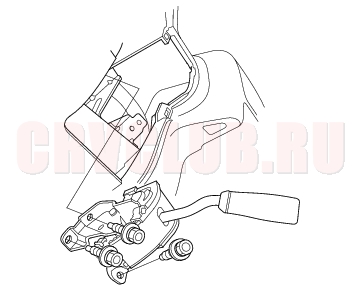
- Remove the shift lever cover.
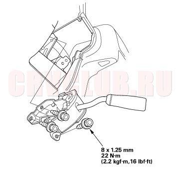
- Remove the control checker (A) from the shift lever, and remove the park pin switch from the control checker.
- Install the new park pin switch (B) by aligning its tab (C) with the positioning hole (D) on the control checker. Apply non-hardening thread lock sealant to the screw (E), then secure the park pin switch with the screw.
- Install the control checker on the shift lever.
- Route the harnesses, and clamp them as shown.
- Install the O/D switch harness terminals (A) in the No. 5 and No. 6 cavities. Both of O/D switch harness terminals can be installed in No. 5 and No. 6 cavities.
- Install the park pin switch harness terminals (B) in the No. 1 and No. 2 cavities. Both of park pin switch harness terminals can be installed in No. 1 and No. 2 cavities.
- Install BLU harness terminal (C) of the shift lock solenoid in the No. 3 cavity, and RED harness terminal (D) in the No. 4 cavity. Make sure that the all six terminals lock securely, then install the back cover (E) locked securely in place.
Park Pin Switch Test/Replacement (cont'd)14-190
- Align the marks (A) on the harnesses, and tie the harness band (B) over the marks. Clamp the O/D switch harness (C) at 15 mm (0.6 in.) (D) from the harness band.
- Install the shift lever cover.
- Install the shift lever assembly.
- NOTE: The illustration shows LHD model; RHD is symmetrical.
- Turn the ignition switch ON (II), and verify that the [R] position indicator comes on.
- If necessary, push the shift cable until it stops, then release it. Pull the shift cable back one step so that the shift cable is in [R]. Do not hold the shift cable guide (A) to adjust the shift cable (B).
- Turn the ignition switch OFF.
- Insert a 6.0 mm (0.24 in.) pin (A) into the positioning holes (B) on the shift lever bracket base through the positioning hole (C) on the shift lever. The shift lever is secured in [R] position.
14-191
- Rotate the socket holder (A) on the shift cable (B) to face the tab (C) on the holder opposite to the opening (D) in the socket holder bracket (E). Align the holder with the opening in the bracket, then slide the holder into the bracket. Rotate the holder a quarter turn to secure the shift cable. Do not install the shift cable by twisting the shift cable guide (F) and damper (G).
LHD Model:
RHD Model:
- Install the shift cable end (A) in the shift cable end holder (B). Keep the shift cable end and end holder free of grease.
- Install the new shift cable lock (A) to secure the shift cable end and shift cable end holder, then push the lock tab (B) up until it stops to lock the joint.
- Remove the 6.0 mm (0.24 in.) pin that was installed to hold the shift lever.
- Connect the O/D switch/shift lock solenoid/park pin switch connector.
- Move the shift lever to each gear, and verify that the A/T gear position indicator follows the transmission range switch.
- Check that the park pin switch operates.
- Install the dashboard gauge assembly cover (see page 20-87) , driver's dashboard lower cover (see page 20-88) , heater control panel (see page 20-91) , front console box, and ash tray.
|
A/T
A/T Interlock System14-172 |