Sunroof20-63
|
Body20-1
Sunroof20-63 |
Sunroof20-63
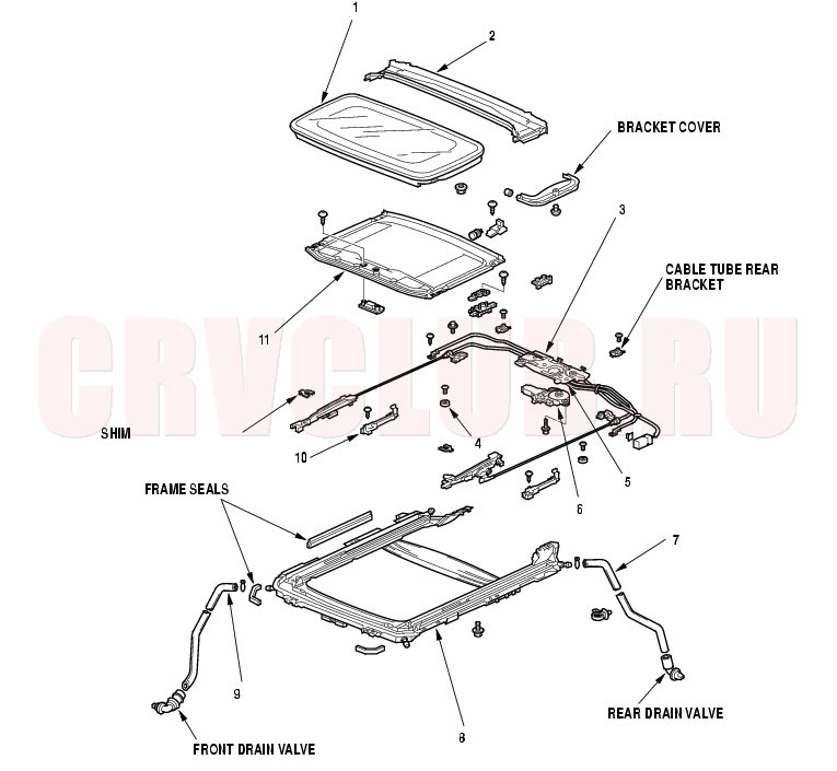
Component Location Index
Height Adjustment, page 20-65 ; Replacement, page 20-65 Closing Force and Opening Drag Check, page 20-74 Replacement, page 20-66 Adjustment, page 20-73 Replacement, page 20-71 Replacement, page 20-68 Replacement, page 20-69 Replacement, page 20-69 Replacement, page 20-69 Replacement, page 20-71 Replacement, page 20-67
Symptom Troubleshooting Index20-64
Water leaks Wind noise Motor noise Glass does not move, but motor turns Glass does not move and motor does not turn (glass can be moved with sunroof wrench)
Glass Height Adjustment20-65
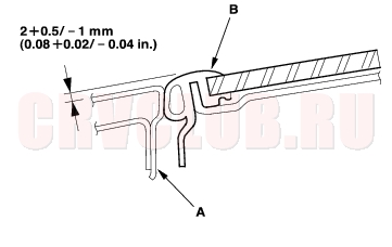
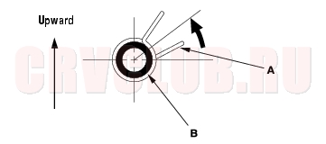
The roof panel (A) should be even with the glass weatherstrip (B), to within 2+0.5/-1 mm (0.08+0.02/-0.04 in.) at the center of the glass opening. If not, make the following adjustment:
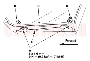
- Remove the bracket cover from each side.
- Loosen the nuts (A), and install the shims (B) between the glass frame (C) and glass bracket (D) on each side.
Shim thickness: Front and rear max. 2 mm (0.08 in.)
Glass Replacement20-65
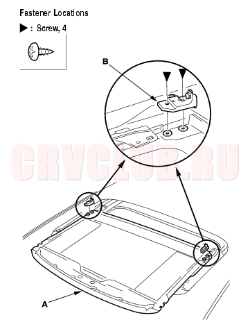
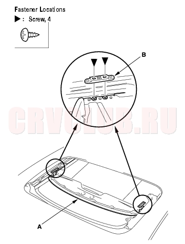
- Close the glass fully.
- Slide the sunshade all the way back.
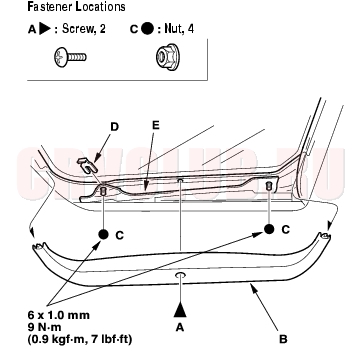
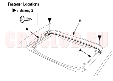
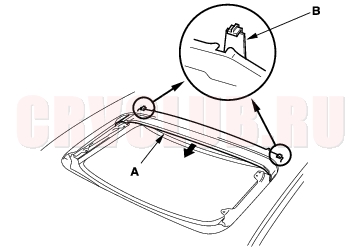
- Remove the screws (A), then remove both bracket covers (B). Remove the nuts (C) and shims (D) from both glass brackets (E).
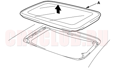
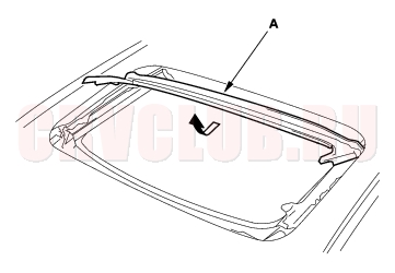
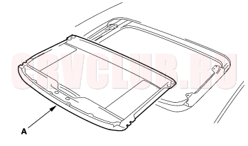
- Remove the glass (A) by lifting it up. Do not damage the roof panel.
- Install the glass in the reverse order of the removal, and adjust the glass height alignment.
- Check for water leaks. Use free-flowing water from a hose without a nozzle. Do not use high-pressure water.
Drain Channel Replacement20-66
- Remove the glass (see page 20-65) .
- With the sunroof wrench, move both glass brackets (A) to the position where the sunroof normally pivots down, and remove the screws securing the drain channel (B).
- Release the drain channel (A) from both hooks (B) of the drain channel slider by pulling the drain channel forward.
- Remove the drain channel (A).
- Install the channel in the reverse order of removal, and note these items:
- Push the drain channel onto the hooks until a faint click is heard.
- Check the glass height adjustment (see page 20-65) .
- Check for water leaks. Let the water run freely from a hose without a nozzle. Do not use a high-pressure spray.
Sunshade Replacement20-67
- Remove the drain channel (see page 20-66) .
- Slide the sunshade (A) until you can see both sunshade slider spacers (B).
- Remove the screws, then remove both spacers.
- While lifting the front portion of the sunshade (A), move the sunshade forward until you can see both sunshade rear hooks (B). Do not damage the sunshade and hooks.
- Remove the screws, then remove both hooks.
Sunshade Replacement (cont'd)20-68
- Remove the sunshade (A).
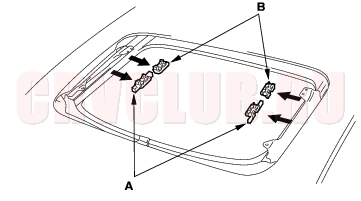
- Remove the front sunshade base sliders (A) and rear sunshade base sliders (B) from both guide rail portions of the frame.
- Install the sunshade in the reverse order of removal, and check the glass height adjustment (see page 20-65) .
- Check for water leaks. Let the water run freely from a hose without a nozzle. Do not use a high-pressure spray.
Motor Replacement20-68
- Remove the headliner (see page 20-81) .
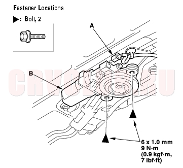
- Put on gloves to protect your hands. Disconnect the connector (A), and remove the bolts, then remove the motor (B).
- Install the motor in the reverse order of removal, and note these items:
- Make sure the connector is plugged in properly.
- Check the motor operation.
Frame and Drain Tube Replacement20-69
NOTE: Put on gloves to protect your hands.
- Remove these items:
- Headliner (see page 20-81)
- Sunroof glass (see page 20-65)
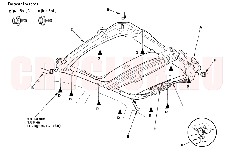
- Disconnect the sunroof connector (A) and drain tubes (B). LHD is shown, RHD is symmetrical.
- With an assistant holding the frame (C), remove the bolts (D) and ground bolt (E), starting at the rear, and release the rear hooks (F) by moving the frame forward, then remove the frame.
- With the help of an assistant, carefully remove the frame through the front door opening.Take care not to scratch the interior trim and body, or tear the seat covers.
Frame and Drain Replacement (cont'd)20-70
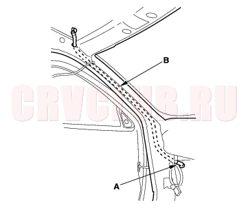
- To remove a front drain valve (A) from the body, remove the kick panel, left or right (see page 20-76) . Tie a string to the end of the drain tube, then pull the front drain tube (B) down out of the front pillar.
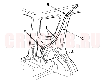
- To remove a rear drain valve (A) from the cargo area, remove these parts:
- Rear side trim panel (see page 20-77)
- Quarter pillar trim (see page 20-78)
- Using a clip remover, detach the clips (B), then remove the rear drain tube (C).
- Install the frame and drain tube in the reverse order of removal, and note these items:
- Before installing the frame, clear the drain tubes and drain valves using compressed air.
- Check the frame seal.
- Clean the surface of the frame.
- When installing the frame, first attach the rear hooks into the body holes.
- Make sure the connector is plugged in properly.
- When connecting the drain tube, slide it over the frame nozzle at least 10 mm (0.39 in.).
- Install the tube clip (A) on the drain tube (B) as shown.
- Check for water leaks. Let the water run freely from a hose without a nozzle. Do not use a high-pressure spray.
Drain Channel Slider and Cable Assembly Replacement20-71
- Remove the frame (see page 20-69) .
- Remove these parts from the frame:
- Drain channel (see page 20-66)
- Sunshade (see page 20-67)
- Sunroof motor (see page 20-68)
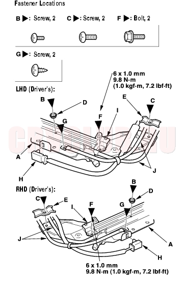
- Put on gloves to protect your hands. From both sides of the frame (A), remove the screws (B, C), then remove the slide stops (D) and cable tube rear brackets (E), and remove the cable tube side bracket mounting bolts (F) and the cable tube mounting screws (G).
- From the driver's side, detach the sunroof connector (H) from the frame.
- Remove the cable tube side brackets (I) and cable tubes (J) from both sides of the frame.
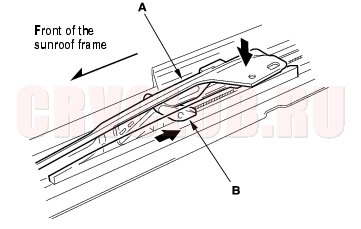
- Pivot the glass bracket (A) down by sliding the link lifter (B) back, then slide both glass brackets back with the link lifter.
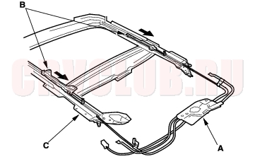
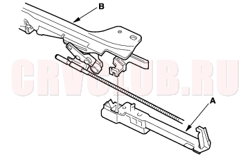
- Slide the cable assembly (A) and both glass brackets (B) back, then remove them from the frame (C).
Drain Channel Slider and Cable Assembly Replacement (cont'd)20-72
- Remove the drain channel sliders (A) from the glass brackets (B) on both sides.
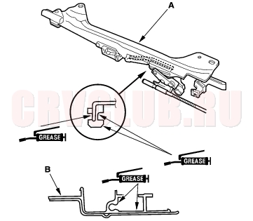
- Install the slider and cable assembly in the reverse order of removal, and note these items:
- Damaged parts should be replaced.
- Apply multipurpose grease to the glass bracket (A) and guide rail portion of the frame (B) indicated by the arrows.
- Before reinstalling the motor, make sure both link lifters are parallel, and in the fully closed position.
- Before reinstalling the motor, install the frame and glass, then check the opening drag (see page 20-74) .
Position Switch Adjustment20-73
- Remove the headliner (see page 20-81) .
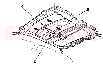
- With the sunroof wrench, close the glass (A) fully:
- Make sure both link lifters (B) are parallel, and in the position shown.
- Check the glass fit to the roof panel and the glass height (see page 20-65) .
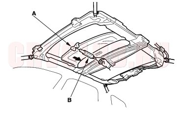
- With an open-end wrench, loosen the position switch mounting bolts (C).
- Adjust the position switch (D):
- Move the switch plate (E) a little at a time, then secure it in the position where you hear a faint click when the switch cam (F) pushes the position switch (open/close).
- Check that the switch plate contacts the switch bracket (F).
- Check the operation of the glass (from the tilt-up position to fully closed position, from the fully open position to the fully closed position) by operating the sunroof switch.
Closing Force and Opening Drag Check20-74
- Remove the headliner (see page 20-81) .
- Closing force check:
- With a shop towel (A) on the leading edge of the glass (B), attach a spring scale (C) as shown.
- Have an assistant hold the switch to close the glass while you measure the force required to stop it.
- Read the force as soon as the glass stops moving, then immediately release the switch and spring scale.
Closing Force: 200 - 290 N (20 - 30 kgf, 44 - 66 lbf)
- If the force is not within specification, remove the sunroof motor (see page 20-68) , then check:
- The gear portion and the inner cable for breakage and damage. If the gear portion is broken, replace the motor. If the inner cable is damaged, remove the frame (see page 20-69) , and replace the cable assembly (see page 20-71) .
- The sunroof motor (see page 22A-128) . If the motor fails to run or doesn't turn smoothly, replace it.
- The opening drag. Go to step 4.
- Opening drag check: Protect the leading edge of the glass with a shop towel (A). Measure the effort required to open the glass using a spring scale (B) as shown.
- If the load is over 40 N (4 kgf, 9 lbf), check:
- The side clearance and glass height adjustment (see page 20-65) .
- For broken or damaged sliding parts. If any sliding parts are damaged, replace them.
|
Body20-1
Sunroof20-63 |