Starting System04-3
|
Engine Electrical04-1
Starting System04-3 |
Starting System04-3
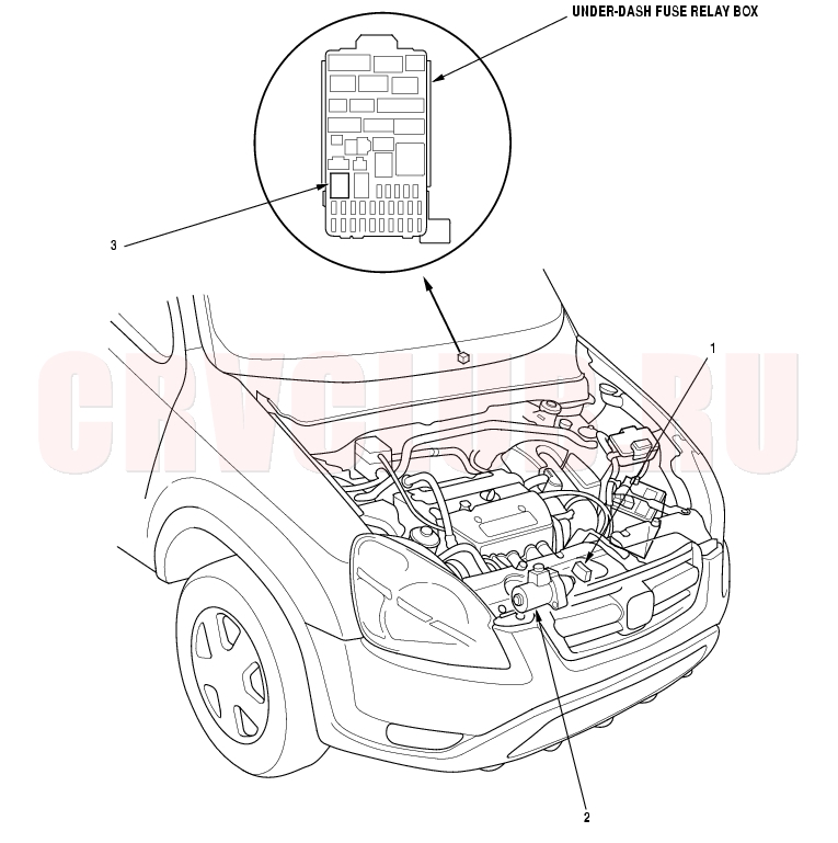
Component Location Index
Test, page 14-168 ; Replacement, page 14-169 Starter Circuit Troubleshooting, page 04-5 ; Solenoid Test, page 04-6 ; Performance, page 04-7 ; Replacement, page 04-9 ; Overhaul, page 04-10 Test, page 22A-60
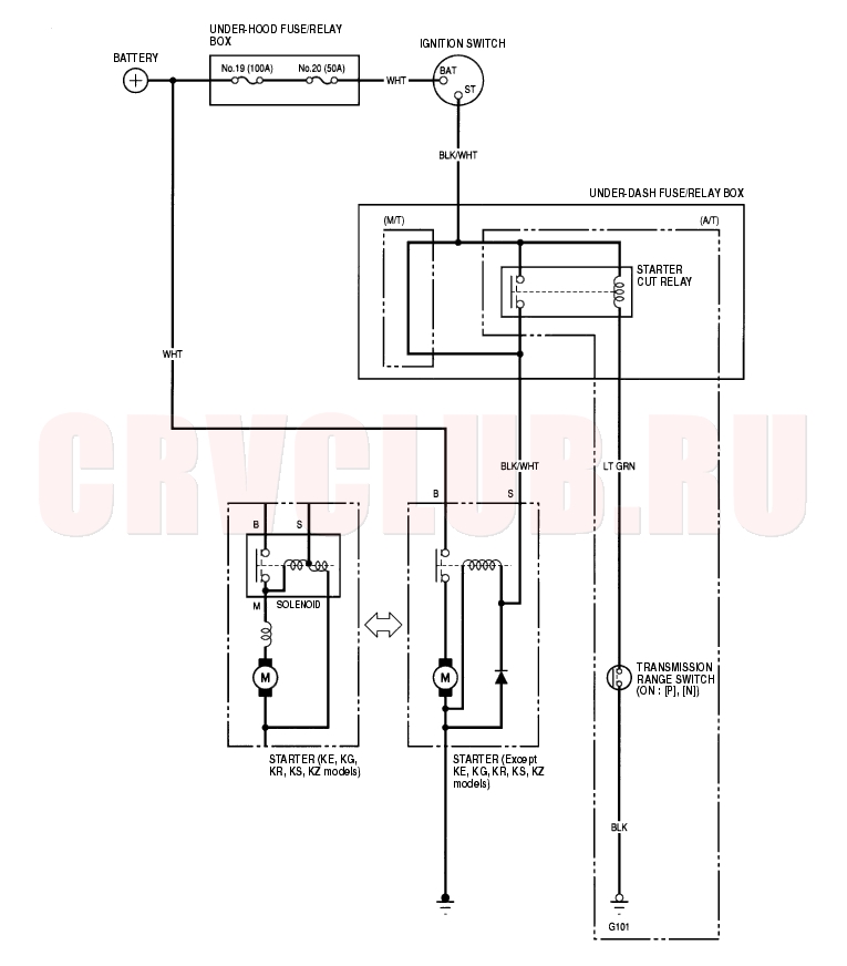
Circuit Diagram04-4
Starter Circuit Troubleshooting04-5
Air temperature must be between 15° and 38°C (59° and 100°F) during this procedure. After this test, or any subsequent repair, reset the Engine Control Module (ECM)/Powertrain Control Module (PCM) to clear any Diagnostic Trouble Codes (DTCs) (see page 11-4) . The battery must be in good condition and full charged (see page 22A-59) .
Use a starter system tester. Connect and operate the equipment in accordance with the manufacturer's instructions. Alternate Procedure
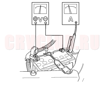
- Hook up the following equipment:
- Ammeter, 0 - 400 A
- Voltmeter, 0 - 20 V (accurate within 0.1 volt)
- Tachometer, 0 - 1200 rpm (min-1)
- Remove the No. 6 (15A) fuse from the under-hood fuse/relay box.
- With the shift lever in [N] or [P] (A/T), turn the ignition switch to start (III).
Did the starter crank the engine normally?
Yes : The starting system is OK.

No : If starter will not crank the engine at all, go to step 4. If it cranks the engine erratically or too slowly, go to step 7. If it won't disengage from the flywheel or torque converter ring gear when you release the key, check for the following until you find the cause.
Solenoid plunger and switch malfunction Dirty drive gear or damaged overrunning clutch
- Check the battery condition. Check electrical connections at the battery, the negative battery cable to body, the engine ground cables and the starter for looseness and corrosion. Then try starting the engine again.
Did the starter crank the engine?
Yes : Repairing the loose connection repaired the problem. The starting system is OK.
No : Go to step 5.
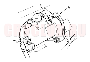
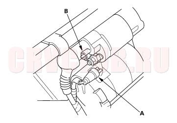
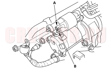
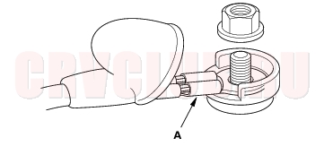
- Make sure the transmission is in neutral, then disconnect the BLK/WHT wire (A) from the starter solenoid (B). Connect a jumper wire from the battery positive terminal to the solenoid terminal.
Except KE, KG, KR, KS, KZ models:
KE, KG, KR, KS, KZ models:
Did the starter crank the engine?
Yes : Go to step 6.
No : Remove the starter, and repair or replace as necessary.
Starter Circuit Troubleshooting (cont'd)04-6
- Check the following items in the order listed until you find the open circuit.
- Check the BLK/WHT wire and connectors between the under-dash fuse/relay box and the ignition switch, and between the under-dash fuse/relay box and the starter.
- Check the ignition switch (see page 11-3) .
- Check the transmission range switch and connector (A/T).
- Check the starter cut relay (A/T).
- Check the engine speed while cranking the engine.
Is the engine speed above 100 rpm (min-1)?
Yes : Go to step 8.
No : Replace the starter, or remove and disassemble it, and check for the following until you find the cause.
Excessively worn starter brushes Open circuit in commutator brushes Dirty or damaged helical splines or drive gear Faulty drive gear clutch Is cranking voltage greater than or equal to 8.5 V (Except KE, KG, KR, KS, KZ models) /8.7 V (KE, KG, KR, KS, KZ models) and current draw less than or equal to 350 A (K20A4 (Except KE, KG, KR, KS, KZ models), K20A5 engines) /380 A (K24A1 engine) /230 A (K20A4 (KE, KG, KR, KS, KZ models) engine) ?
Yes : Go to step 9.
No : Replace the starter, or remove and disassemble it, and check for the following until you find the cause.
Open circuit in starter armature commutator segments Starter armature dragging Shorted armature winding Excessive drag in engine
- Remove the starter, and inspect its drive gear and the flywheel or torque converter ring gear for damage. Replace any damaged parts.
Starter Solenoid Test04-6
KE, KG, KR, KS, KZ models
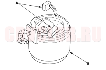
- Check the hold-in coil for continuity between the S terminal (A) and the armature housing (ground). There should be continuity.
- If there is continuity, go to step 2.
- If there is no continuity, replace the solenoid.
- Check the pull-in coil for continuity between the S terminal (A) and M terminal (B). There should be continuity.
- If there is continuity, the solenoid is OK.
- If there is no continuity, replace the solenoid.
Starter Performance Test04-7
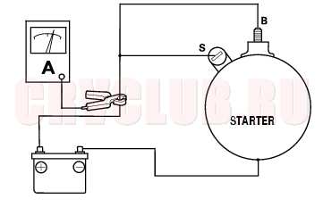
Except KE, KG, KR, KS, KZ models
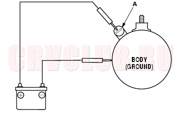
- Disconnect the wire from the S terminal (A).
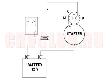
- Make the connections as described below using as heavy a wire as possible (preferably equivalent to the wire used for the vehicle). To avoid damaging the starter, never leave the battery connected for more than 10 seconds.
- Connect the battery as shown. If the starter pinion moves out, it is working properly.
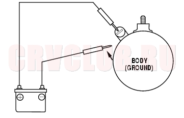
- Disconnect the battery from the body. If the pinion retracts immediately, it is working properly.
- Clamp the starter firmly in a vise.
- Connect the starter to the battery as described in the diagram below, and confirm that the motor starts and keeps rotating.
- If the electric current and motor speed meet the specifications when the battery voltage is at 11.5 V, the starter is working properly.
Specifications:
Electric current: 80 A or less
Motor speed:
K20A4, K20A5 engines: 2,600 rpm (min-1) or more
K24A1 engine: 2,300 rpm (min-1) or more
Starter Performance Test (cont'd)04-8
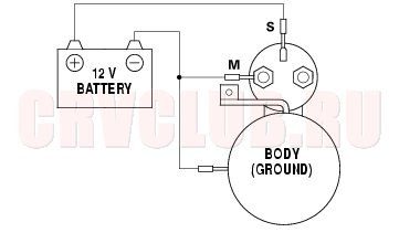
KE, KG, KR, KS, KZ models
- Disconnect the wires from the S terminal and the M terminal.
- Make the connections as described below using as heavy a wire as possible (preferably equivalent to the wire used for the vehicle). To avoid damaging the starter, never leave the battery connected for more than 10 seconds.
- Connect the battery as shown. If the starter pinion moves out, it is working properly.
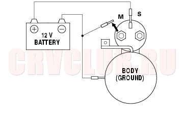
- Disconnect the battery from the M terminal. If the pinion does not retract, the hold-in coil is working properly.
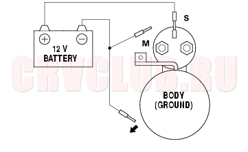
- Disconnect the battery from the body. If the pinion retracts immediately, it is working properly.
- Clamp the starter firmly in a vise.
- Connect the starter to the battery as described in the diagram below, and confirm that the motor starts and keeps rotating.
- If the electric current and motor speed meet the specifications when the battery voltage is at 11.5 V, the starter is working properly.
Specifications:
Electric current: 90 A or less
Motor speed: 3,000 rpm (min-1) or more
Starter Replacement04-9
- Disconnect the battery negative cable, then disconnect the positive cable.
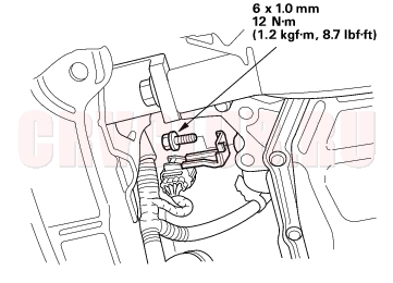
- Disconnect the knock sensor connector.
- Disconnect the bolt securing the harness bracket.
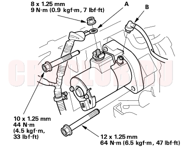
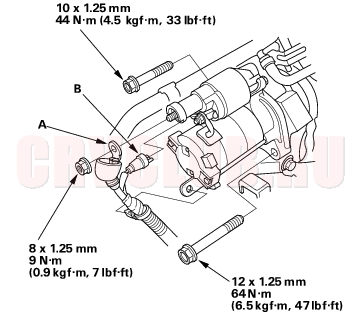
- Disconnect the starter cable (A) from the B terminal on the solenoid, then disconnect the BLK/WHT wire (B) from the S terminal.
Except KE, KG, KR, KS, KZ models:
KE, KG, KR, KS, KZ models:
- Remove the two bolts holding the starter, then remove the starter.
- Install the starter in the reverse order of removal. Make sure the crimped side of the ring terminal (A) is facing out.
- Connect the battery positive cable and negative cable to the battery.
- Start the engine to make sure the starter operates properly.
Starter Overhaul04-10
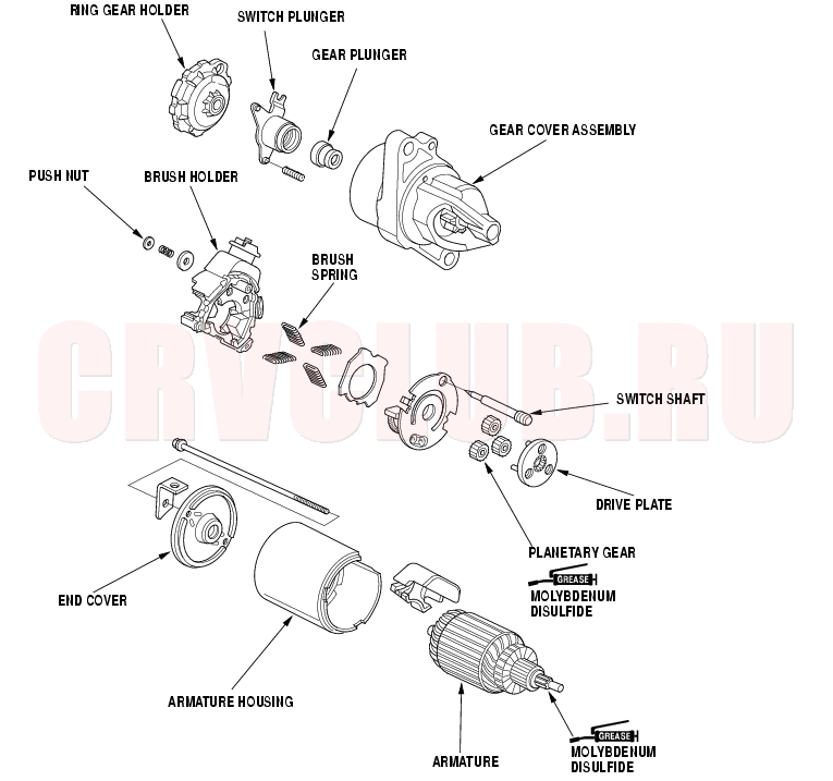
Disassembly/Reassembly-Except KE, KG, KR, KS, KZ models
04-11
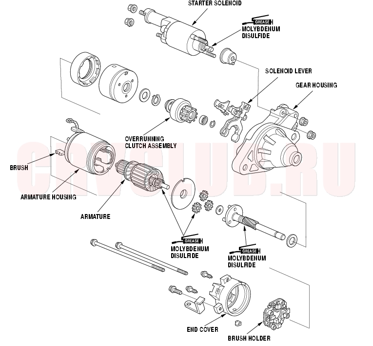
Disassembly/Reassembly-KE, KG, KR, KS, KZ models
Starter Overhaul (cont'd)04-12
Armature Inspection and Test
- Remove the starter (see page 04-9) .
- Disassemble the starter as shown at the beginning of this procedure.
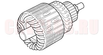
- Inspect the armature for wear or damage from contact with the permanent magnet. If there is wear or damage, replace the armature.
- Check the commutator (A) surface. If the surface is dirty or burnt, resurface with emery cloth or a lathe within the following specifications, or recondition with #500 or #600 sandpaper (B).
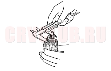
- Check the commutator diameter. If the diameter is below the service limit, replace the armature.
Commutator Diameter:
Except KE, KG, KR, KS, KZ models:
Standard (New): 28. 0 - 28.1 mm
(1.102 - 1.106 in.)
Service Limit: 27.5 mm (1.083 in.)
KE, KG, KR, KS, KZ models:
Standard (New): 28.0 mm (1.10 in.)
Service Limit: 27.0 mm (1.06 in.)
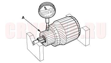
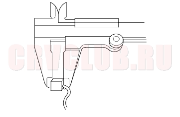
- Measure the commutator (A) runout.
- If the commutator runout is within the service limit, check the commutator for carbon dust or brass chips between the segments.
- If the commutator runout is not within the service limit, replace the armature.
Commutator Runout
Standard (New): 0.02 mm (0.001in.) max
Service Limit: 0.05 mm (0.002 in.)
04-13
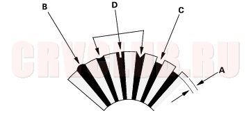
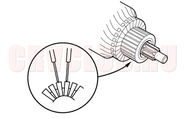
- Check the mica depth (A). If the mica is too high (B), undercut the mica with a hacksaw blade to the proper depth. Cut away all the mica (C) between the commutator segments. The undercut should not be too shallow, too narrow, or V-shaped (D).
Commutator Mica Depth:
Except KE, KG, KR, KS, KZ models:
Standard (New): 0.40 - 0.50 mm (0.016 - 0.020 in.)
Service Limit: 0.15 mm (0.006 in.)
KE, KG, KR, KS, KZ models:
Standard (New): 0.50 - 0.80 mm (0.020 - 0.031 in.)
Service Limit: 0.20 mm (0.008 in.)
- Check for continuity between the segments of the commutator. If an open circuit exists between any segments, replace the armature.
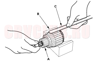
- Place the armature (A) on an armature tester (B). Hold a hacksaw blade (C) on the armature core. If the blade is attracted to the core or vibrates while the core is turned, the armature is shorted. Replace the armature.
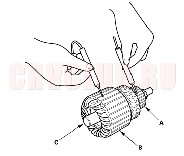
- Check with an ohmmeter that no continuity exists between the commutator (A) and armature coil core (B), and between the commutator and armature shaft (C). If continuity exists, replace the armature.
Starter Overhaul (cont'd)04-14
Starter Brush Inspection
Brush Length
Except KE, KG, KR, KS, KZ models:
Standard (New): 11.1 - 11.5 mm (0.44 - 0.45 in.)
Service Limit: 4.3 mm (0.17 in.)
KE, KG, KR, KS, KZ models:
Standard (New): 14.0 - 14.5 mm (0.55 - 0.57 in.)
Service Limit: 9.0 mm (0.35 in.)
Starter Field Winding Test (KE, KG, KR, KS, KZ models)
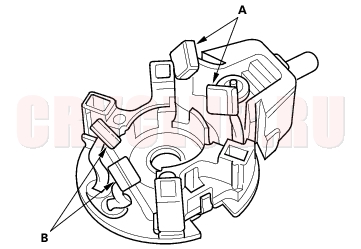
- Check for continuity between the brushes (A). If there is no continuity, replace the armature housing (B).
- Check for continuity between each brush (A) and the armature housing (B). If there is continuity, replace the armature housing.
Starter Brush Holder Test
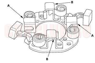
- Check that there is no continuity between the (+) brush holder (A) and (-) brush holder (B). If there is continuity, replace the brush holder assembly.
Excpet KE, KG, KR, KS, KZ models:
KE, KG, KR, KS, KZ models:
04-15
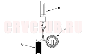
Brush Spring Inspection (KE, KG, KR, KS, KZ models)
- Insert the brush (A) into the brush holder, and bring the brush into contact with the commutator, then attach a spring scale (B) to the spring (C). Measure the spring tension at the moment the spring lifts off the brush. If the spring tension is not within specification, replace the spring.
Spring Tension: 13.7 - 17.7 N (1.40 - 1.80 kgf,
3.09 - 3.97 lbf)
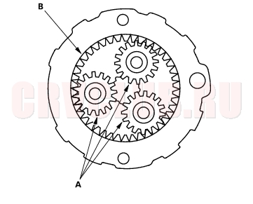
Planetary Gear Inspection
Overrunning Clutch Inspection (Except KE, KG, KR, KS, KZ models)
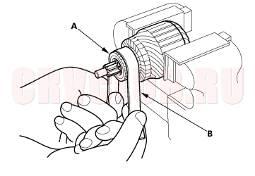
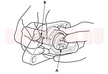
- Holding the drive gear (A), turn the gear shaft (B) clockwise. Check that the drive gear comes out to the other end. If the drive gear does not move smoothly, replace the gear cover assembly.
- Holding the drive gear, turn the gear shaft counterclockwise. The gear shaft should rotate freely. If the gear shaft does not rotate smoothly, replace the gear cover assembly.
- If the starter drive gear is worn or damaged, replace the overrunning clutch assembly; the gear is not available separately.
Check the condition of the flywheel or torque converter ring gear. Replace it if the starter drive gear teeth are damaged.
Starter Overhaul (cont'd)04-16
Overrunning Clutch Inspection (KE, KG, KR, KS, KZ models)
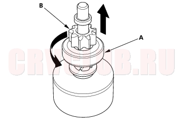
- Slide the overrunning clutch along the shaft.
Replace it, if it does not slide smoothly.
- Rotate the overrunning clutch (A) both ways.
Does it lock in one direction and rotate smoothly in reverse? If it does not lock in either direction or it locks in both directions, replace it.
- If the starter drive gear (B) is worn or damaged, replace the overrunning clutch assembly; the gear is not available separately.
Check the condition of the flywheel ring gear. Replace it if the starter drive gear teeth are damaged.
Starter Reassembly (Except KE, KG, KR, KS, KZ models)
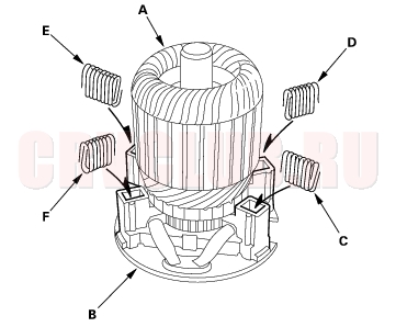
- Install the brush into the brush holder, and set the armature (A) in the brush holder (B).
- NOTE: To seat the new brushes, slip a strip of #500 or #600 sandpaper, with the grit side up, between the commutator and each brush, and smoothly rotate the armature. The contact surface of the brushes will be sanded to the same contour as the commutator.
- Squeezing a spring (C), insert it in the hole on the brush holder, and push it until it bottoms. Repeat this for the other three springs (D, E and F).
- Install the armature and brush holder assembly into the housing.
- NOTE: Make sure the armature stays in the holder.
04-17
Starter Reassembly (KE, KG, KR, KS, KZ models)
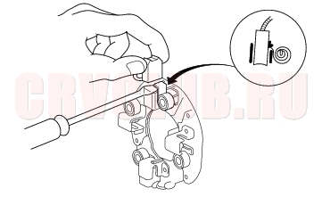
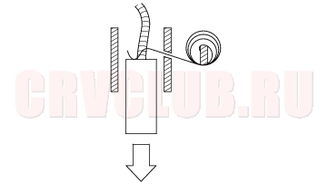
- Pry back each brush spring with a screwdriver, then position the brush about halfway out of its holder, and release the spring to hold it there.
- NOTE: To seat the new brushes, slip a strip of #500 or #600 sandpaper, with the grit side up, between the commutator and each brush, and smoothly rotate the armature. The contact surface of the brushes will be sanded to the same contour as the commutator.
- Install the armature in the housing, and install the brush holder. Next, pry back each brush spring again, and push the brush down until it seats against the commutator, then release the spring against the end of the brush.
- Install the starter end cover to retain the brush holder.
|
Engine Electrical04-1
Starting System04-3 |