Fuel and Emissions Systems11-2
|
Fuel and Emissions11-1
Fuel and Emissions Systems11-2 |
Fuel and Emissions Systems11-2
Special Tools
General Troubleshooting Information11-3
Intermittent Failures
The term ''intermittent failure'' means a system may have had a failure, but it checks OK now. If the Malfunction Indicator Lamp (MIL) on the dash does not come on, check for poor connections or loose wires at all connectors related to the circuit that you are troubleshooting.
Opens and Shorts
''Open'' and ''Short'' are common electrical terms. An open is a break in a wire or at a connection. A short is an accidental connection of a wire to ground or to another wire. In simple electronics, this usually means something won't work at all. In complex electronics (like ECM's/PCM's) this can sometimes mean something works, but not the way it's supposed to.
How to Use the Honda PGM Tester or a Scan Tool
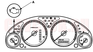
If the MIL has come on
- Start the engine and check the MIL.
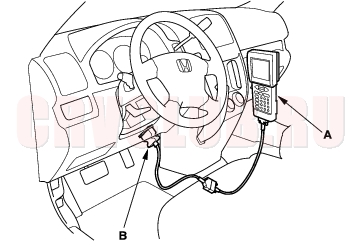
- If the MIL stays on, connect the Honda PGM Tester (A) or a scan tool to the Data Link Connector (DLC) (B) located under the driver's side of the dashboard.
*: The illustration shows LHD model.
- Turn the ignition switch ON (II).
- Check the Diagnostic Trouble Code (DTC) and note it. Also check the freeze frame data. Refer to the DTC Troubleshooting Index and begin the appropriate troubleshooting procedure.
Freeze frame data indicates the engine conditions when the first malfunction, misfire or fuel trim malfunction was detected. The scan tool and the Honda PGM Tester can read the DTC, freeze frame data, current data, and other Engine Control Module (ECM)/Powertrain Control Module (PCM) data. For specific operations, refer to the user's manual that came with the scan tool or Honda PGM Tester. If the MIL did not come on
If the MIL did not come on but there is a driveability problem, refer to the Symptom Troubleshooting Index in this section (see page 11-8) .
If you can't duplicate the DTC
Some of the troubleshooting in this section requires you to reset the ECM/PCM and try to duplicate the DTC. If the problem is intermittent and you can't duplicate the code, do not continue through the procedure. To do so will only result in confusion and, possibly, a needlessly replaced ECM/PCM.
General Troubleshooting Information (cont'd)11-4
How to Reset the ECM/PCM
You can reset the ECM/PCM in either of 2 ways:
Use the scan tool or Honda PGM Tester to clear the ECM's/PCM's memory.
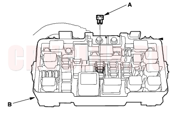
See the scan tool or Honda PGM Tester user's manuals for specific instructions.Turn the ignition switch OFF, and remove the No. 6 ECU (ECM/PCM) (15A) fuse (A) from the under-hood fuse/relay box (B) for 10 seconds.
How to End a Troubleshooting Session (required after any troubleshooting)
- Reset the ECM/PCM as described above.
- Turn the ignition switch OFF.
- Disconnect the scan tool or Honda PGM Tester from the DLC.
- NOTE: The ECM/PCM is part of the immobilizer system. If you replace the ECM/PCM, it will have a different immobilizer code. In order for the engine to start, you must rewrite the immobilizer code with the Honda PGM Tester.
How to Remove the ECM/PCM for Testing
If the inspection for a trouble code requires voltage or resistance checks at the ECM/PCM connectors, remove the ECM/PCM and test it:
- Make sure you have the anti-theft code for the radio, then write down the radio station presets.
- Disconnect the negative cable from the battery.
- Remove the glove box (see page 20-95) .
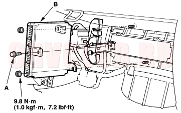
- Remove the gray 20P ECM/PCM wire harness connector from the ECM/PCM mounting bracket. Remove the ECM/PCM mounting bolt (A) and the bracket.
*: The illustration shows LHD model.
- Remove the nuts, then remove the ECM/PCM (B).
- Install the ECM/PCM in the reverse order of removal.
- Reconnect the negative cable to the battery.
- Enter the radio anti-theft code and the radio station preset then set the clock.
11-5
How to Troubleshoot Circuits at the ECM/PCM
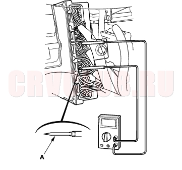
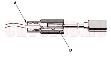
- Gently slide the sharp tester probe (A) into the connector from wire side until it touches the end of the wire terminal.
- If you cannot get to the wire side of the connector or the wire side is sealed (A), disconnect the connector and probe the terminals (B) from the terminal side. Do not force the probe into the connector.
NOTICE
Do not puncture the insulation on a wire.Punctures can cause poor or intermittent electrical connections.
How to Substitute the ECM/PCM
- Disconnect the negative cable from the battery.
- Remove the ECM/PCM from the vehicle.
- Install a known-good ECM/PCM in the vehicle.
- Reconnect the negative cable to the battery.
- Rewrite the immobilizer code with the ECM/PCM replacement procedure on the Honda PGM Tester. It allows you to start the engine.
- After completing your tests, reinstall the original ECM/PCM and rewrite the immobilizer code with the ECM/PCM replacement procedure on the Honda PGM Tester again.
DTC Troubleshooting Index11-6
P0010 (56-1) VTC Oil Control Solenoid Valve Malfunction (see page 11-124) P0011 (56-2) VTC System Malfunction (see page 11-126) P0107 (3-1) Manifold Absolute Pressure (MAP) Sensor Circuit Low Voltage (see page 11-62) ) P0108 (3-2) Manifold Absolute Pressure (MAP) Sensor Circuit High Voltage (see page 11-63) P0112 (10-1) Intake Air Temperature (IAT) Sensor Circuit Low Voltage (see page 11-64) P0113 (10-2) Intake Air Temperature (IAT) Sensor Circuit High Voltage (see page 11-65) P0117 (6-1) Engine Coolant Temperature (ECT) Sensor Circuit Low Voltage (see page 11-66) P0118 (6-2) Engine Coolant Temperature (ECT) Sensor Circuit High Voltage (see page 11-67) P0122 (7-1) Throttle Position (TP) Sensor Circuit Low Voltage (see page 11-68) P0123 (7-2) Throttle Position (TP) Sensor Circuit High Voltage (see page 11-70) P0131 (1-1)* 4 Primary Heated Oxygen Sensor (Primary HO2S) (Sensor 1) Circuit Low Voltage (see page 11-71) P0132 (1-2)* 4 Primary Heated Oxygen Sensor (Primary HO2S) (Sensor 1) Circuit High Voltage (see page 11-72) P0133 (61-1)* 3 * Primary Heated Oxygen Sensor (Primary HO2S) (Sensor 1) Slow Response (see page 11-73) P0135 (41-2)* 4 Primary Heated Oxygen Sensor (Primary HO2S) (Sensor 1) Heater Circuit Malfunction (see page 11-74) P0137 (63-1)* 5 * Secondary Heated Oxygen Sensor (Secondary HO2S) (Sensor 2) Circuit Low Voltage (see page 11-76) P0138 (63-2)* 5 * Secondary Heated Oxygen Sensor (Secondary HO2S) (Sensor 2) Circuit High Voltage (see page 11-77) P0141 (65-2)* 5 Secondary Heated Oxygen Sensor (Secondary HO2S) (Sensor 2) Heater Circuit Malfunction (see page 11-78) P0171 (45-2)* 3 * Fuel system Too Lean (see page 11-80) P0172 (45-1)* 3 * Fuel system Too Rich (see page 11-80) P0300 (7x-1)* 3 * Random Misfire (see page 11-81) P0301 (71-1)* 3 * No. 1 Cylinder Misfire (see page 11-81) P0302 (72-1)* 3 * No. 2 Cylinder Misfire (see page 11-81) P0303 (73-1)* 3 * No. 3 Cylinder Misfire (see page 11-81) P0304 (74-1)* 3 * No. 4 Cylinder Misfire (see page 11-81)
* : These DTCs have Temporary DTC code.
*3: KG, KS, KE, KR, KU (Hong Kong) models
*5: KG, KS, KE, KR, KU, KZ, FO, KQ models
*6: KG, KS, KE, KR, KU, KZ, FO, KQ, KK, KM models
*7: except KG, KS, KE, KR, KU (Hong Kong) models
11-7
P0325 (23-1) Knock Sensor Circuit Malfunction (see page 11-87) P0335 (4-1) Crankshaft Position (CKP) Sensor No Signal (see page 11-88) P0336 (4-2) Crankshaft Position (CKP) Sensor Intermittent Interruption (see page 11-88) P0340 (57-1) Camshaft Position (CMP) Sensor No Signal (see page 11-128) P0341 (57-3) VTC Phase Gap (see page 11-129) P0344 (57-2) Camshaft Position (CMP) Sensor Intermittent Interruption (see page 11-128) P0420 (67-1)* 3 * Catalyst System Efficiency Below Threshold (see page 11-188) P0443 (92-4)* 3 Evaporative Emission (EVAP) Canister Purge Valve Circuit Malfunction (see page 11-193) P0500 (17-1)* 2 Vehicle Speed Sensor (VSS) Circuit Malfunction (see page 11-90) P0563 (34-2) Engine Control Module (ECM)/Powertrain Control Module (PCM) Power Source Circuit Unexpected Voltage (see page 11-91) P0600 (39-1) Serial Communication Link Malfunction Refer to the Multiplex Control System Troubleshooting (see page 22A-231) P07xx, P08xx* 1 (70-2, 70-3)* 1 * Automatic Transaxle System Malfunction Refer to the Automatic Transmission DTC Troubleshooting Index (see page 14-7) P1107 (13-1) Barometric Pressure (BARO) Sensor Circuit Low Voltage (see page 11-93) P1108 (13-2) Barometric Pressure (BARO) Sensor Circuit High Voltage (see page 11-93) P1213 (11-1)* 8 Idle Mixture Adjuster (IMA) Circuit Low Voltage (see page 11-94) P1214 (11-2)* 8 Idle Mixture Adjuster (IMA) Circuit High Voltage (see page 11-95) P1253 (21-1)* 7 VTEC System Malfunction (see page 11-130) P1259 (22-4)* 3 VTEC System Malfunction (see page 11-133) P1297 (20-1)* 6 Electrical Load Detector (ELD) Circuit Low Voltage (see page 11-97) P1298 (20-2)* 6 Electrical Load Detector (ELD) Circuit High Voltage (see page 11-98) P1361 (8-2) Top Dead Center (TDC) Sensor Intermittent Interruption (see page 11-100) P1362 (8-1) Top Dead Center (TDC) Sensor No Signal (see page 11-100) P1519 (14-3) Idle Air Control (IAC) Valve Circuit Malfunction (see page 11-140) P1607 (0-2) Engine Control Module (ECM)/Powertrain Control Module (PCM) Internal Circuit Malfunction (see page 11-101) P17xx (70-2, 70-3)* 1 * Automatic Transaxle System Malfunction Refer to the Automatic Transmission DTC Troubleshooting Index (see page 14-7)
* : These DTCs have Temporary DTC code.
*3: KG, KS, KE, KR, KU (Hong Kong) models
*5: KG, KS, KE, KR, KU, KZ, FO, KQ models
*6: KG, KS, KE, KR, KU, KZ, FO, KQ, KK, KM models
*7: except KG, KS, KE, KR, KU (Hong Kong) models
Symptom Troubleshooting Index11-8
When the vehicle has one of these symptoms, check the Diagnostic Trouble Code (DTC) with the scan tool. If there is no DTC, do the diagnostic procedure for the symptom, in the sequence listed, until you find the cause.
Engine will not start (MIL works OK, no DTCs set)
- Test the battery (see page 22A-59) .
- Test the starter (see page 04-5) .
- Troubleshoot the fuel pump circuit (see page 11-151) .
Low compression No ignition spark Intake air leaks Locked up engine Slipped/ broken timing belt Contaminated fuel Engine will not start (MIL comes on and stays on, or never comes on at all, no DTCs set) Troubleshoot the MIL circuit (see page 11-102) . Engine will not start (immobilizer indicator light stays on or flashes) Troubleshoot the immobilizer system (see page 22A-190) . Hard starting (MIL works OK, no DTCs set)
- Test the battery (see page 22A-59) .
- Check the fuel pressure (see page 11-154) .
Low compression Intake air leaks Contaminated fuel Weak spark Cold fast idle too low (MIL works OK, no DTCs set) Check the idle speed (see page 11-148) . Cold fast idle too high (MIL works OK, no DTCs set)
- Check the idle speed (see page 11-148) .
- Inspect/adjust the throttle cable (see page 11-183) .
- Inspect and test the throttle body (see page 11-180) .
Idle speed fluctuates (MIL works OK, no DTCs set)
- Check the idle speed (see page 11-148) .
- Inspect/adjust the throttle cable (see page 11-183) .
- Inspect and test the throttle body (see page 11-180) .
Intake air leaks After warming up idle speed is below specifications with no load (MIL works OK, no DTCs set)
- Troubleshoot the ALT FR signal circuit (see page 11-143) .* 1
- Inspect and test the throttle body (see page 11-180) .
Vacuum hose clogged/ cracked/poor connection After warming up idle speed is above specifications with no load*1 (MIL works OK, no DTCs set) Troubleshoot the ALT FR signal circuit (see page 11-143) . After warming up idle speed drops when steering wheel is turning (MIL works OK, no DTCs set)
- Troubleshoot the PSP switch signal circuit (see page 11-145) .
- Inspect and test the throttle body (see page 11-180) .
Power steering system Idle speed fluctuates (MIL works OK, no DTCs set)
- Test the fuel pressure (see page 11-154) .
- Test the injectors (see page 11-116) .* 2
- Troubleshoot the ALT FR signal circuit (see page 11-143) .
- Inspect and test the PCV valve (see page 11-190) .
Contaminated fuel
11-9
Misfire or rough running (MIL works OK, no DTCs set)
- Check the spark plugs (see page 04-23) .* 2
- Test the fuel pressure (see page 11-154) .
- Test the injectors (see page 11-116) .* 2
- Troubleshoot the fuel pump circuit (see page 11-151) .
Low compression Valve clearance Contaminated fuel Fails emission test* 2 (MIL works OK, no DTCs set)
- Inspect the three way catalytic converter (TWC) (see page 11-188) .
- Check the spark plugs (see page 04-23) .
- Test the fuel pressure (see page 11-154) .
- Test the injectors (see page 11-116) .
- Check the EVAP emission control system (see page 11-195) .
Contaminated fuel Low compression Slipped/broken timing belt Low power (MIL works OK, no DTCs set)
- Test the fuel pressure (see page 11-154) .
- Check the air cleaner element (see page 11-182) .
- Inspect/adjust the throttle cable (see page 11-183) .
- Inspect and the test the throttle body (see page 11-180) .
- Inspect the three way catalytic converter (TWC) (see page 11-188) .* 2
- Test the injectors (see page 11-116) .* 2
Contaminated fuel Low compression Camshaft timing Engine oil level Engine stalls (MIL works OK, no DTCs)
- Test the fuel pressure (see page 11-154) .
- Check the idle speed (see page 11-148) .
- Troubleshoot the brake pedal position switch signal circuit (see page 11-146) .
- Check the spark plugs (see page 04-23) .* 2
Intake air leaks Faulty harness and sensor connections
*1: except KG, KS, KE, KR, KU, KZ, FO, KQ, KK, KM models
*2: except KG, KS, KE, KR, KU (Hong Kong) models
System Descriptions11-10
Electronic Control System
The functions of the fuel and emission control systems are managed by the Engine Control Module (ECM) on vehicles with manual transmissions or the Powertrain Control Module (PCM) on vehicles with automatic transmissions.
Fail-safe Function
When an abnormality occurs in a signal from a sensor, the ECM/PCM ignores that signal and assumes a pre-programmed value for that sensor that allows the engine to continue to run.
Back-up Function
When an abnormality occurs in the ECM/PCM, the injectors are controlled by a back-up circuit independent of the system to permit minimal driving.
Self-diagnosis
When an abnormality occurs in the signal from a sensor, the ECM/PCM supplies ground for the Malfunction Indicator Lamp (MIL) and stores the Diagnostic Trouble Code (DTC) in erasable memory. When the ignition is first turned on, the ECM/PCM supplies ground for the MIL for 2 seconds to check the MIL bulb condition.
Two Driving Cycle Detection Method
To prevent false indications, the ''two driving cycle detection method'' is used for some self-diagnostic functions. When an abnormality occurs, the ECM/PCM stores it in its memory. When the same abnormality recurs after the ignition switch is turned OFF and ON (II) again, the ECM/PCM informs the driver by turning on the MIL.
11-11
ECM/PCM Data
You can retrieve data from the ECM/PCM by connecting the scan tool or the Honda PGM Tester to the Data Link Connector (DLC). The items listed in the table below conform to SAE recommended practice. The Honda PGM Tester also reads data beyond that recommended by SAE so that this data may help you find the causes of intermittent problems.
The ''operating values'' listed are approximate and may vary depending on the environment and the individual vehicle. Unless noted otherwise, ''at idle speed'' means idling with the engine completely warmed up, A/T in Park or neutral, M/T in neutral position, and the A/C and all accessories turned off.
System Descriptions (cont'd)11-12
11-13
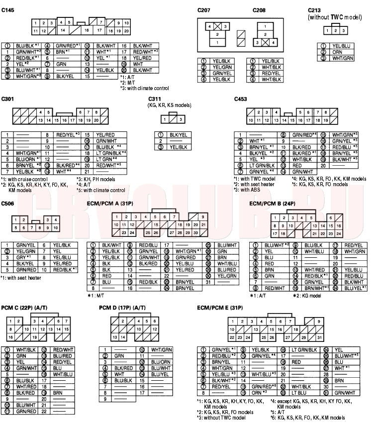
ECM/PCM Inputs and Outputs at Connector A (31P)
NOTE: Standard battery voltage is 12 V.
*4: KG, KS, KE, KR, KU, KZ, FO, KQ, KK, KM models
*5: KG, KS, KE, KR, KU (Hong Kong) models
*6: KG, KS, KE, KR, KU, KZ, FO, KQ models
*7: KG, KS, KE, KR, KU, KN, KH, KY, KZ, FO, KQ, KK, KM models
*8: except KG, KS, KE, KR, KU, KN, KH, KY, KZ, FO, KQ, KK, KM models
*10: with cruise controlSystem Descriptions (cont'd)11-14
ECM/PCM Inputs and Outputs at Connector B (24P)
NOTE: Standard battery voltage is 12 V.
*4: KG, KS, KE, KR, KU, KZ, FO, KQ, KK, KM models
*5: KG, KS, KE, KR, KU (Hong Kong) models
*6: KG, KS, KE, KR, KU, KZ, FO, KQ models
*7: KG, KS, KE, KR, KU, KN, KH, KY, KZ, FO, KQ, KK, KM models
*8: except KG, KS, KE, KR, KU, KN, KH, KY, KZ, FO, KQ, KK, KM models
11-15
PCM Inputs and Outputs at Connector C (22P)* 1
NOTE: Standard battery voltage is 12 V.
*4: KG, KS, KE, KR, KU, KZ, FO, KQ, KK, KM models
*5: KG, KS, KE, KR, KU (Hong Kong) models
*6: KG, KS, KE, KR, KU, KZ, FO, KQ models
*7: KG, KS, KE, KR, KU, KN, KH, KY, KZ, FO, KQ, KK, KM models
*8: except KG, KS, KE, KR, KU, KN, KH, KY, KZ, FO, KQ, KK, KM models
System Descriptions (cont'd)11-16
PCM Inputs and Outputs at Connector D (17P)
NOTE: Standard battery voltage is 12 V.
*4: KG, KS, KE, KR, KU, KZ, FO, KQ, KK, KM models
*5: KG, KS, KE, KR, KU (Hong Kong) models
*6: KG, KS, KE, KR, KU, KZ, FO, KQ models
*7: KG, KS, KE, KR, KU, KN, KH, KY, KZ, FO, KQ, KK, KM models
*8: except KG, KS, KE, KR, KU, KN, KH, KY, KZ, FO, KQ, KK, KM models
11-17
ECM/PCM Inputs and Outputs at Connector E (31P)
NOTE: Standard battery voltage is 12 V.
*4: KG, KS, KE, KR, KU, KZ, FO, KQ, KK, KM models
*5: KG, KS, KE, KR, KU (Hong Kong) model
*6: KG, KS, KE, KR, KU, KZ, FO, KQ models
*7: KG, KS, KE, KR, KU, KN, KH, KY, KZ, FO, KQ, KK, KM models
*8: except KG, KS, KE, KR, KU, KN, KH, KY, KZ, FO, KQ, KK, KM models
System Descriptions (cont'd)11-18
Vacuum Hose Routing
11-19
Vacuum Distribution
*1: KG, Ks, KE, KR, KU, KZ, FO, KQ models *5: except KZ, PH, FO, IN, MA models
*2: KN, KM, KY, MA, PH, IN, KK models *6: KZ, PH, FO, IN, MA models
*3: without TWC model
*4: with TWC model
System Descriptions (cont'd)11-20
PGM-FI System
The Programmed Fuel Injection (PGM-FI) system is a sequential multiport fuel injection system.
Air Conditioning (A/C) Compressor Clutch Relay
When the ECM/PCM receives a demand for cooling from the A/C system, it delays the compressor from being energized, and enriches the mixture to assure smooth transition to the A/C mode.
Alternator Control
The alternator signals the Engine Control Module (ECM)/Powertrain Control Module (PCM) during charging.
Barometric Pressure (BARO) Sensor
The BARO sensor is inside the ECM/PCM. It converts atmospheric pressure into a voltage signal that modifies the basic duration of the fuel injection discharge.
Crankshaft Position (CKP) Sensor
The CKP sensor detects crankshaft speed and determines ignition timing and timing for fuel injection of each cylinder, as well as detecting engine misfire.
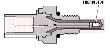
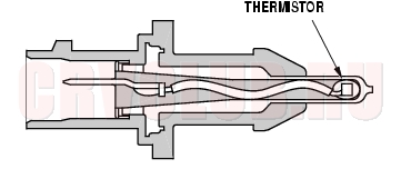
Engine Coolant Temperature (ECT) Sensor
The ECT sensor is a temperature dependent resistor (thermistor). The resistor of the thermistor decreases as the engine coolant temperature increases.
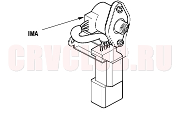
Idle Mixture Adjuster (IMA) (without TWA model)
The idle mixture adjuster (IMA) is selected resistance device used to control idle mixture.
Ignition Timing Control
The ECM/PCM contains the memory for basic ignition timing at various engine speeds and manifold absolute pressure. It also adjusts the timing according to engine coolant temperature.
Injector Timing and Duration
The ECM/PCM contains the memory for basic discharge duration at various engine speeds and manifold pressures. The basic discharge duration, after being read out from the memory, is further modified by signals sent from various sensors to obtain the final discharge duration.
By monitoring long term fuel trim, the ECM/PCM detects long term malfunctions in the fuel system, and will set a Diagnostic Trouble Code (DTC).
11-21
Intake Air Temperature (IAT) Sensor
The IAT sensor is a temperature dependent resistor (thermistor). The resistance of the thermistor decreases as the intake air temperature increases.
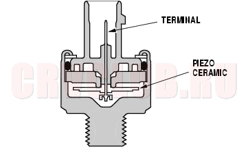
Knock Sensor
The knock control system adjusts the ignition timing to minimize knock.
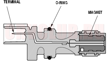
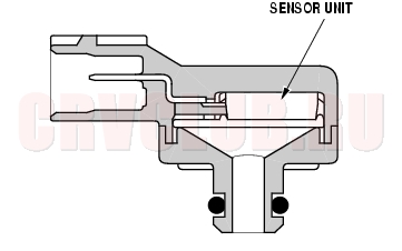
Manifold Absolute Pressure (MAP) Sensor
The MAP sensor converts manifold absolute pressure into electrical signals to the ECM/PCM.
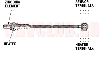
Primary Heated Oxygen Sensor (Primary HO2S)
The primary HO2S detects the oxygen content in the exhaust gas and sends signals to the ECM/PCM which varies the duration of fuel injection accordingly. To stabilize its output, the sensor has an internal heater. The primary HO2S is installed in the Three Way Catalytic Converter (TWC). By controlling the air fuel ratio with primary HO2S and secondary HO2S, the deterioration of the primary HO2S can be evaluated by its feedback period. When the feedback period exceeds a certain value during stable driving conditions, the sensor is considered deteriorated and the ECM/PCM sets a DTC.
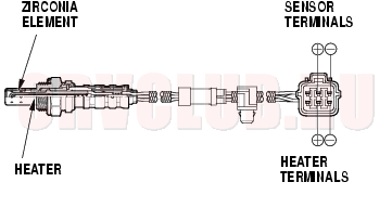
Secondary Heated Oxygen Sensor (Secondary HO2S)
The secondary HO2S detects the oxygen content in the exhaust gas downstream of the Three Way Catalytic Converter (TWC) and sends signals to the ECM/PCM which varies the duration of fuel injection accordingly. To stabilize its output, the sensor has an internal heater. The secondary HO2S is installed in the TWC.
Starting Control
When the engine is started, the ECM/PCM provides a rich mixture by increasing injector duration.
System Descriptions (cont'd)11-22
PGM-FI System (cont'd)
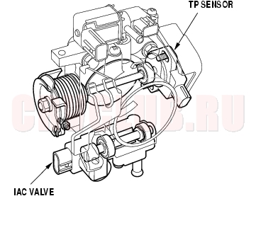
Throttle Position (TP) Sensor
The TP sensor is a potentiometer connected to the throttle valve shaft. As the throttle position changes, the sensor varies the signal voltage to the ECM/PCM. The TP sensor is not replaceable apart from the throttle body.
Top Dead Center (TDC) Sensor
The TDC sensor detects the position of the No. 1 cylinder as a reference for sequential fuel injection to each cylinder.
Vehicle Speed Sensor (VSS)
The VSS is driven by the differential. It generates a pulsed signal from an input of 5 volts. The number of pulses per minute increases/decreases with the speed of the vehicle.
11-23
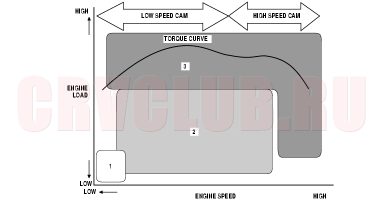
VTEC/VTC
The i-VTEC has a VTC (Variable Valve Timing Control) mechanism on the intake camshaft in addition to the usual VTEC.
This mechanism improves fuel efficiency and reduces exhaust emissions at all levels of engine speed, vehicle speed, and engine load.The VTEC mechanism changes the valve lift and timing by using more than one cam profile. The VTC changes the phase of the intake camshaft via oil pressure. It changes the intake valve timing continuously.
System Descriptions (cont'd)11-24
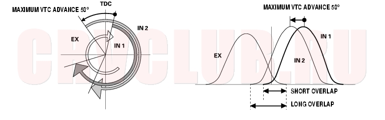
VTEC/VTC
VTC system
The VTC system makes continuous intake valve timing changes based on operating conditions. Intake valve timing to allow the engine to produce maximum power. Cam angle is advanced to obtain the EGR effect and reduce the pumping loss. The intake valve is closed quickly to reduce the entry of the air/fuel mixture into the intake port and improve the charging effect. Reduces the cam advance at idle, stabilizes combustion, and reduces engine speed. If a malfunction occurs, the VTC system control is disabled and the valve timing is fixed at the fully retarded position.
VTEC system
The VTEC system changes the cam profile to correspond to the engine speed. It maximizes torque at low engine speed and output at high engine speed. The low lift cam is used at low engine speeds, and the high lift cam is used at high engine speeds.
11-25
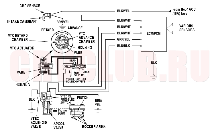
System Diagram
Camshaft Position (CMP) Sensor
The CMP sensor detects camshaft angle position for the VTC system.
System Descriptions (cont'd)11-26
Idle Control System
When the engine is cold, the A/C compressor is on, the transmission is in gear, the brake pedal is pressed, the power steering load is high, or the alternator is charging, the ECM/PCM controls current to the Idle Air Control (IAC) valve to maintain the correct idle speed. Refer to the System Diagram to see the functional layout of the system.
Brake Pedal Position Switch
The brake pedal position switch signals the ECM/PCM when the brake pedal is pressed.
Idle Air Control (IAC) Valve
To maintain the proper idle speed, the IAC valve changes the amount of air bypassing the throttle body in response to an electrical signal from the ECM/PCM.
Power Steering Pressure (PSP) Switch
The PSP switch signals the ECM/PCM when the power steering load is high.
Fuel Supply System
Fuel Cut-off Control
During deceleration with the throttle valve closed, current to the injectors is cut off to improve fuel economy at speeds over 850 rpm (min-1) (KY, KH, PH, KP, IN models: 900 rpm (min-1)). Fuel cut-off action also occurs when engine speed exceeds 6,900 rpm (min-1) (K24A1 engine: 6,700 rpm (min-1)), regardless of the position of the throttle valve, to protect the engine from over-revving. When the vehicle is stopped, the ECM/PCM cuts the fuel at engine speeds over 6,500 rpm (min-1) (A/T: 5,000 rpm (min-1)).
Fuel Pump Control
When the ignition is turned on, the ECM/PCM grounds the PGM-FI main relay which feeds current to the fuel pump for 2 seconds to pressurize the fuel system. With the engine running, the ECM/PCM grounds the PGM-FI main relay and feeds current to the fuel pump. When the engine is not running and the ignition is on, the ECM/PCM cuts ground to the PGM-FI main relay which cuts current to the fuel pump.
PGM-FI Main Relay 1 and 2
The PGM-FI relay consists of two separate relays. PGM-FI main relay 1 is energized whenever the ignition switch is ON (II) which supplies battery voltage to the ECM/PCM, power to the injectors, and power for the PGM-FI main relay 2. PGM-FI main relay 2 is energized to supply power to the fuel pump for 2 seconds when the ignition switch is turned ON (II), and when the engine is running.
11-27
Intake Air System
Refer to the System Diagram to see the functional layout of the system.
Throttle Body
The throttle body is a single-barrel side draft type. The lower portion of the IAC valve is heated by engine coolant from the cylinder head.
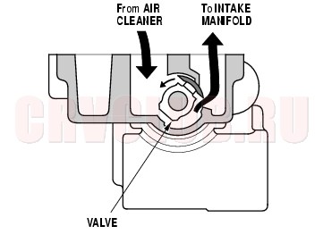
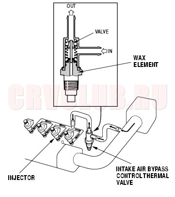
Intake Air Bypass Control Thermal Valve
When the engine is running, the intake air bypass control thermal valve sends air to the injector.
System Descriptions (cont'd)11-28
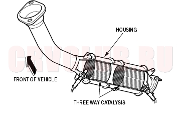
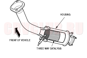
Catalytic Converter System
Three Way Catalytic Converter (TWC)
The TWC converts hydrocarbons (HC), carbon monoxide (CO), and oxides of nitrogen (NOx) in the exhaust gas to carbon dioxide (CO2), dinitrogen (N2), and water vapor.
KG, KS, KE, KR, KU, KZ, FO, KQ, models:
KN, KM, KY, MA, PH, IN, KK models:
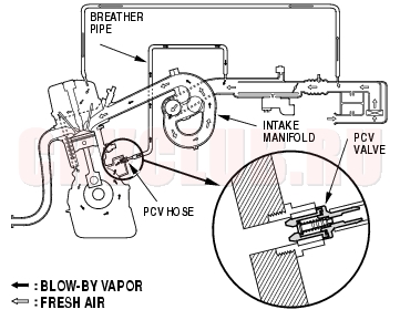
Positive Crankcase Ventilation (PCV) System
The PCV valve prevents blow-by gasses from escaping into the atmosphere by venting them into the intake manifold.
Evaporative Emission (EVAP) Control System
Refer to the System Diagram to see the functional layout of the system.
EVAP Canister
The EVAP canister temporarily stores fuel vapor from the fuel tank until it can be purged back into the engine and burned (refer to the System Diagram to see the functional layout of the system).
EVAP Canister Purge Valve
When the engine coolant temperature is below 65°C (149°F), the ECM/PCM turns off the EVAP canister purge valve which cuts vacuum to the EVAP canister.
11-29
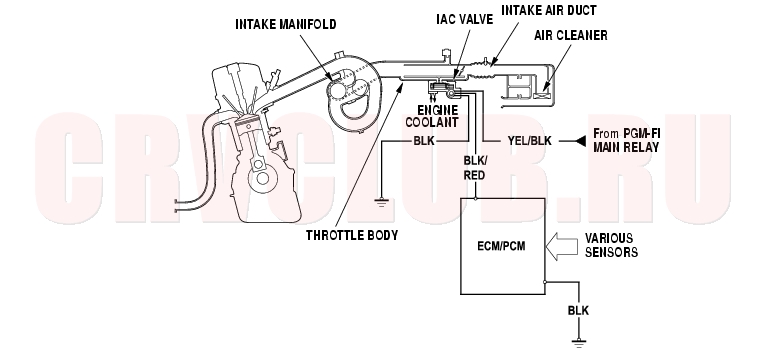
Idle Control System Diagram
The idle speed of the engine is controlled by the Idle Air Control (IAC) valve:
After the engine starts, the IAC valve opens for a certain amount of time. The amount of air is increased to raise the idle speed. When the engine coolant temperature is low, the IAC valve is opened to obtain the proper fast idle speed. The amount of bypassed air is thus controlled in relation to engine coolant temperature.
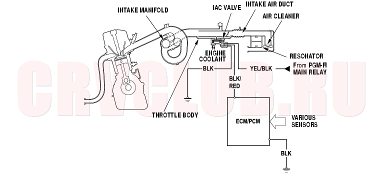
Intake Air System Diagram
This system supplies air for engine needs. A resonator in the intake air pipe provides additional silencing as air is drawn into the system.
System Descriptions (cont'd)11-30
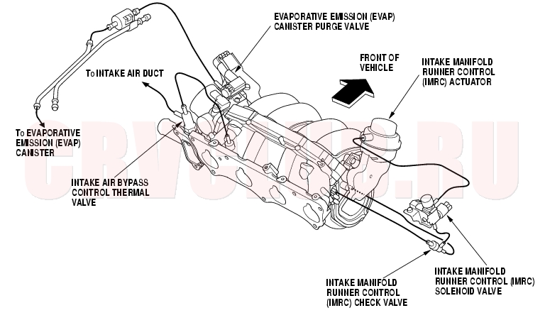
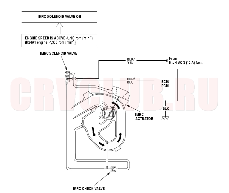
Intake Manifold Runner Control (IMRC) System
Satisfactory power performance is achieved by closing and opening the Intake Manifold Runner Control (IMRC) valve. High torque at low engine speed is achieved when the valve is closed, whereas high power at high engine is achieved when the valve is opened.
11-31
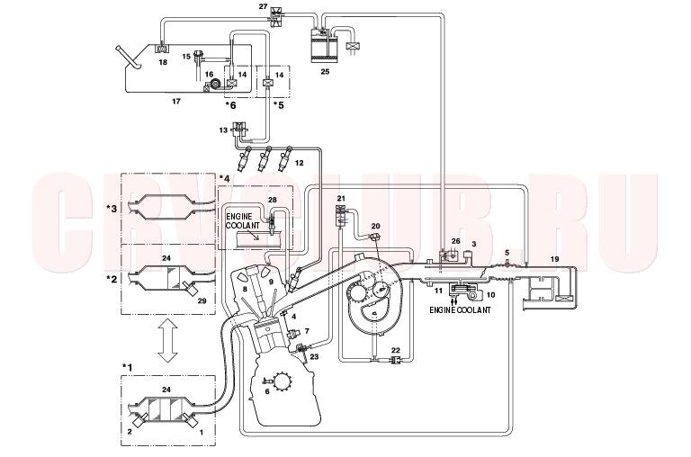
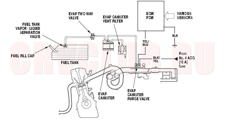
Evaporative Emission (EVAP) Control Diagram
The EVAP controls minimize the amount of fuel vapor escaping to the atmosphere. Vapor from the fuel tank is temporarily stored in the EVAP canister until it can be purged from the EVAP canister into the engine and burned.
The EVAP canister is purged by drawing fresh air through it and into a port on the intake manifold. The purging vacuum is controlled by the EVAP canister purge valve, which is open whenever engine coolant temperature is above 65°C (149°F). When vapor pressure in the fuel tank is higher than the set value of the EVAP two way valve, the valve opens and regulates the flow of fuel vapor to the EVAP canister.
System Descriptions (cont'd)11-32
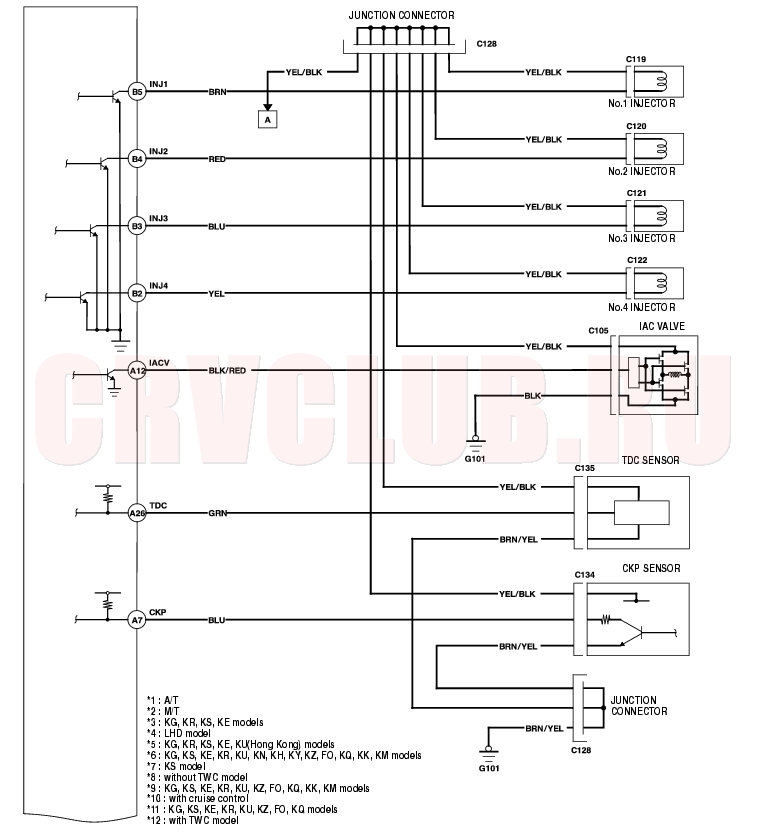
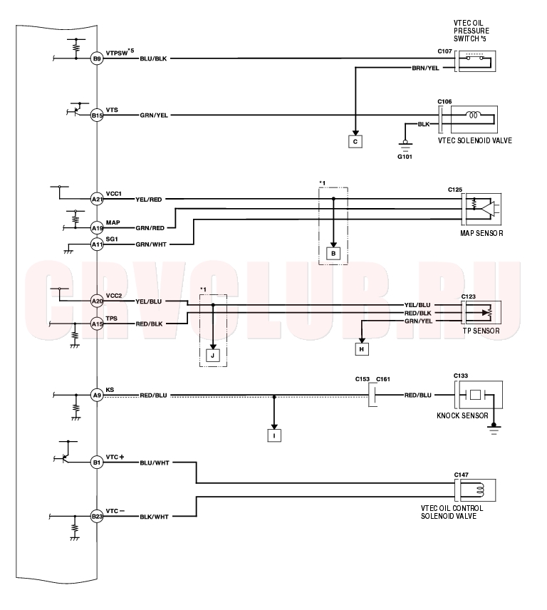
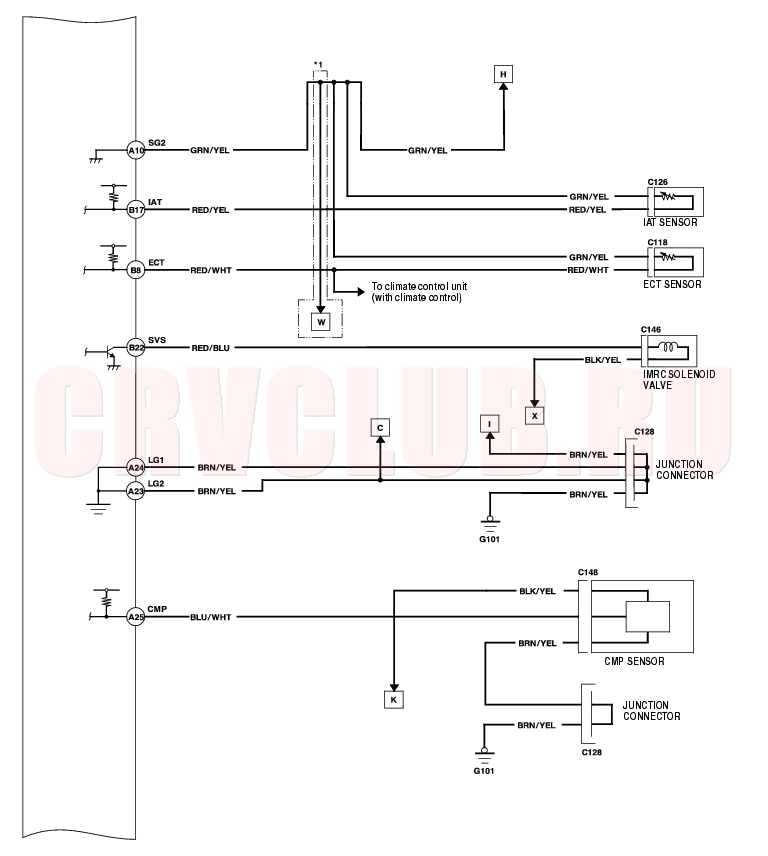
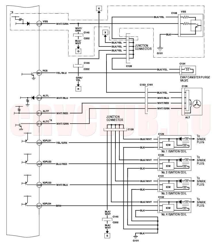
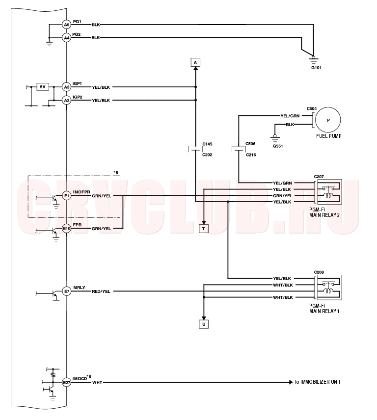
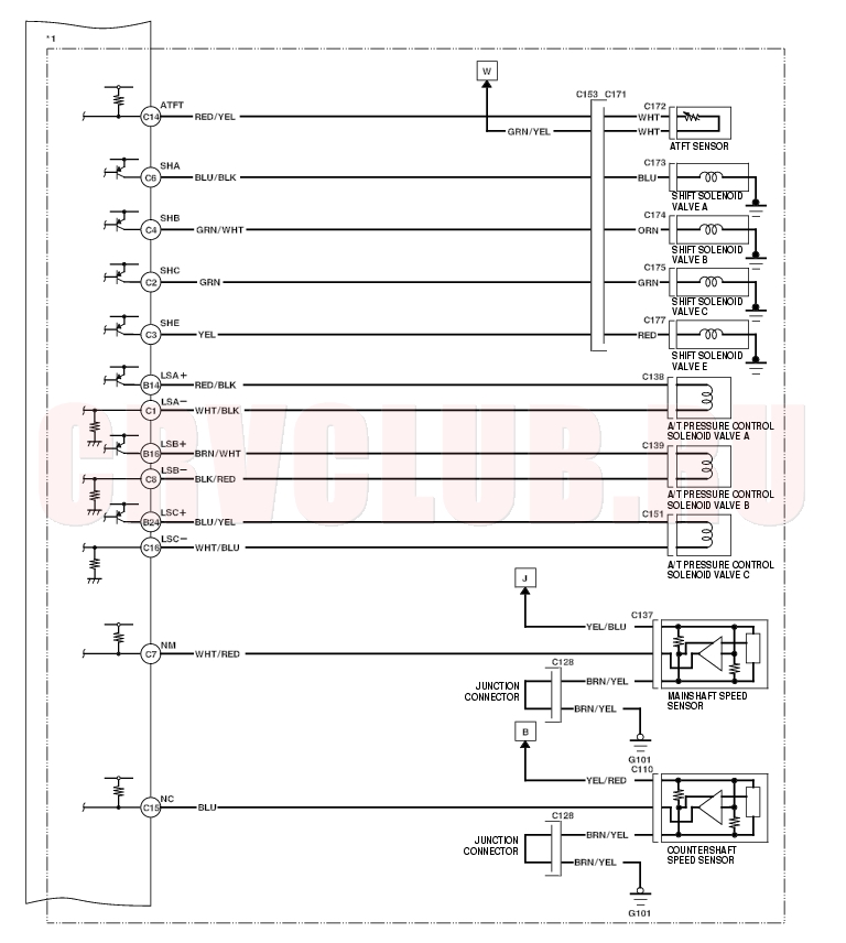
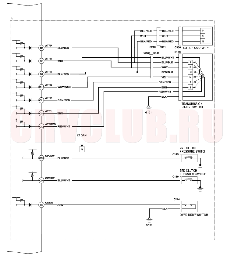
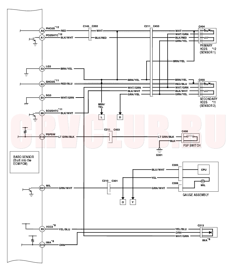
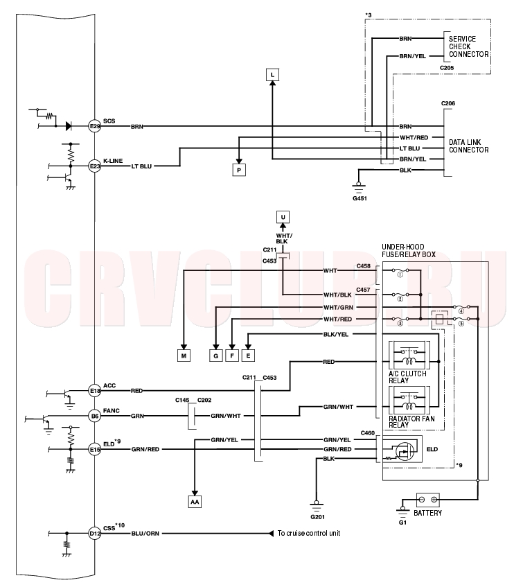
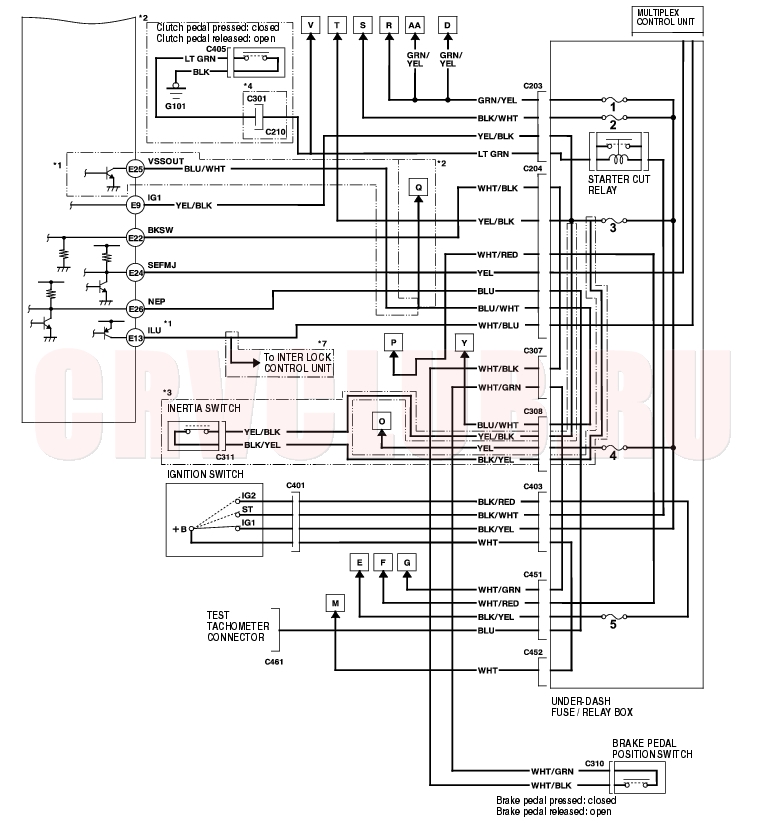
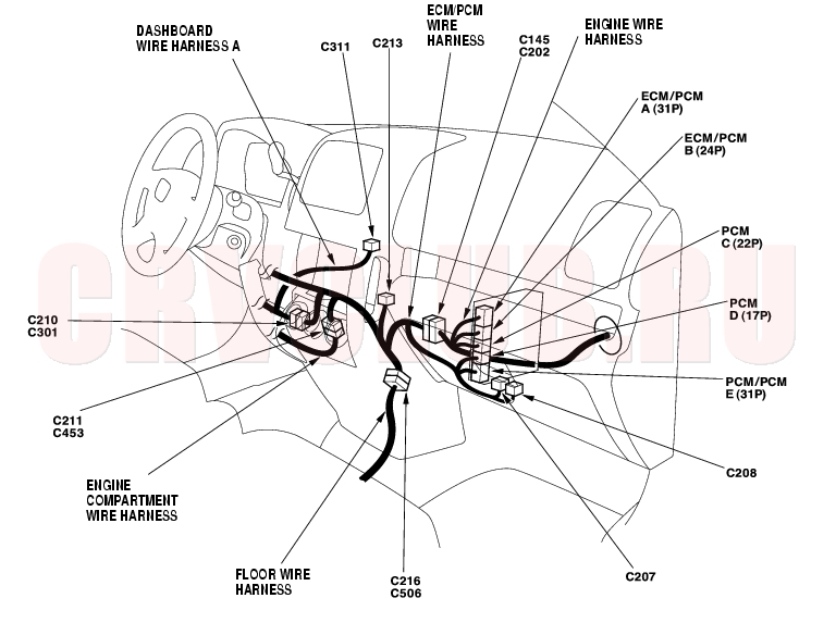
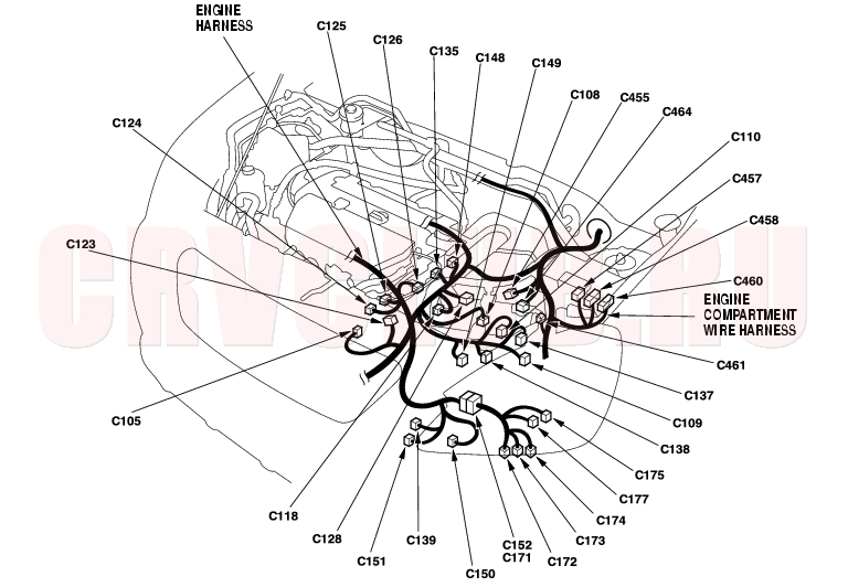
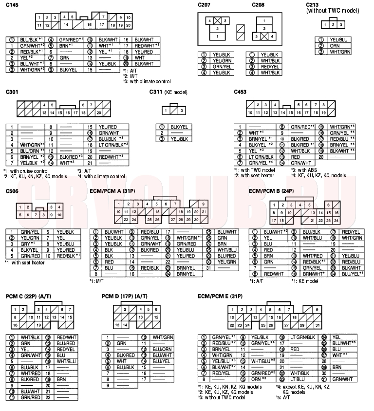
ECM/PCM Circuit Diagram
11-33
System Descriptions (cont'd)11-34
11-35
System Descriptions (cont'd)11-36
11-37
System Descriptions (cont'd)11-38
11-39
System Descriptions (cont'd)11-40
11-41
System Descriptions (cont'd)11-42
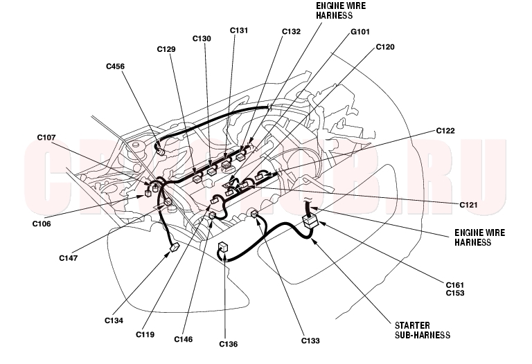
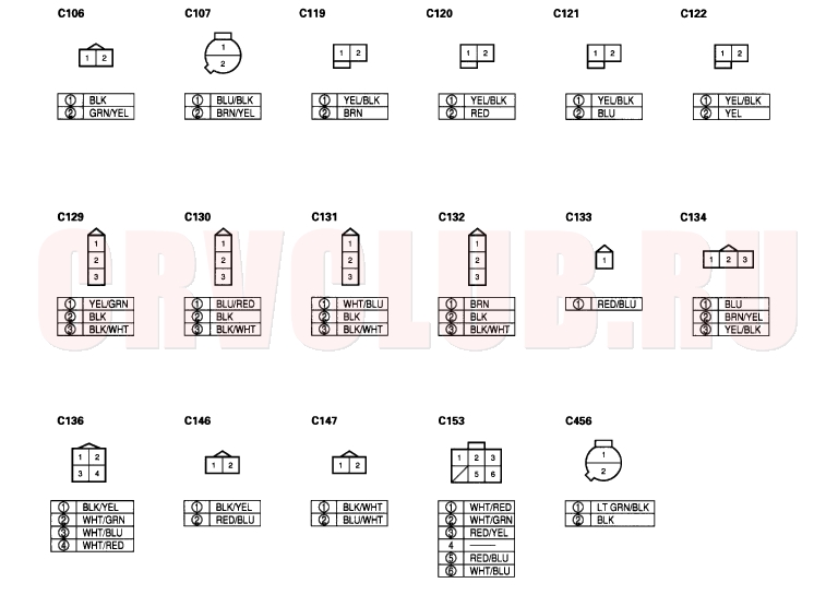
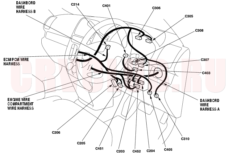
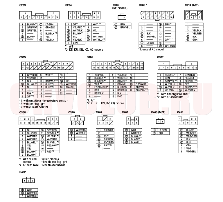
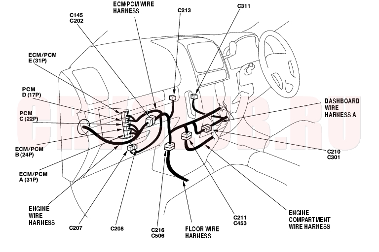
LHD model:
11-43
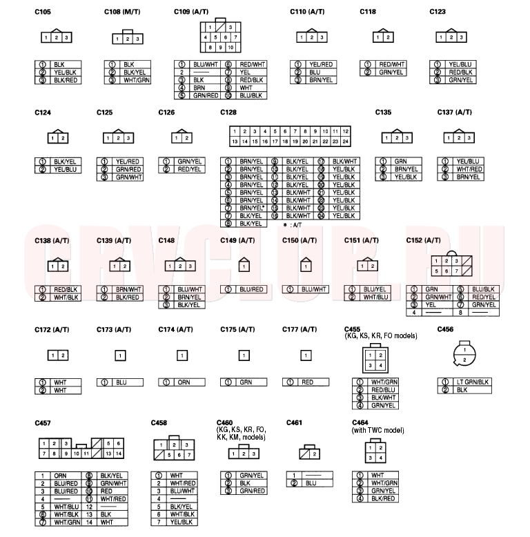
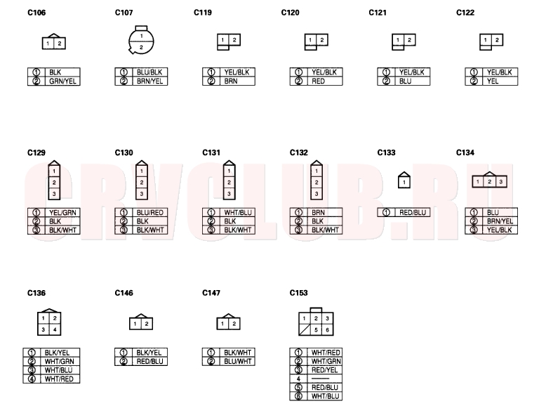
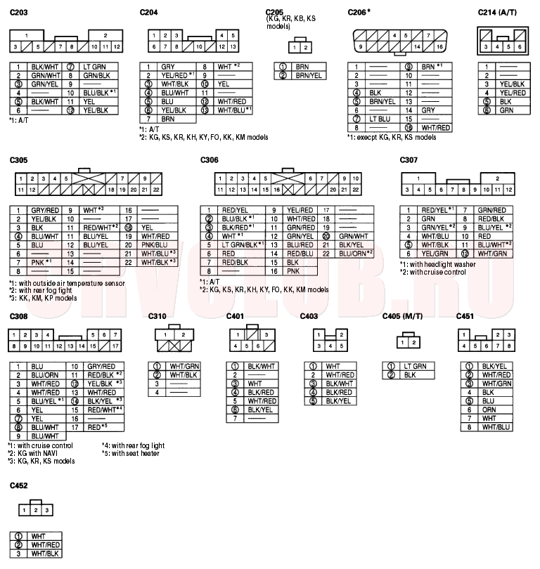
Note: · Connector with male terminals (double outline): View from terminal side
· Connector with female terminals (single outline): View from wire side
· O : Related to ECM/PCM control
System Descriptions (cont'd)11-44
LHD model:
11-45
Note: · Connector with male terminals (double outline): View from terminal side
· Connector with female terminals (single outline): View from wire side
· O : Related to ECM/PCM control
System Descriptions (cont'd)11-46
LHD model:
11-47
Note: · Connector with male terminals (double outline): View from terminal side
· Connector with female terminals (single outline): View from wire side
· O : Related to ECM/PCM control
·
: Terminal side of female terminals
System Descriptions (cont'd)11-48
LHD model:
11-49
Note: · Connector with male terminals (double outline): View from terminal side
· Connector with female terminals (single outline): View from wire side
· O : Related to ECM/PCM control
System Descriptions (cont'd)11-50
RHD model:
11-51
Note: · Connector with male terminals (double outline): View from terminal side
· Connector with female terminals (single outline): View from wire side
· O : Related to ECM/PCM control
System Descriptions (cont'd)11-52
RHD model:
11-53
Note: · Connector with male terminals (double outline): View from terminal side
· Connector with female terminals (single outline): View from wire side
· O : Related to ECM/PCM control
System Descriptions (cont'd)11-54
RHD model:
11-55
Note: · Connector with male terminals (double outline): View from terminal side
· Connector with female terminals (single outline): View from wire side
· O : Related to ECM/PCM control
·
: Terminal side of female terminals
System Descriptions (cont'd)11-56
RHD model:
11-57
Note: · Connector with male terminals (double outline): View from terminal side
· Connector with female terminals (single outline): View from wire side
· O : Related to ECM/PCM control
System Descriptions (cont'd)11-58
Note: · Connector with male terminals (double outline): View from terminal side
· Connector with female terminals (single outline): View from wire side
· O : Related to ECM/PCM control
|
Fuel and Emissions11-1
Fuel and Emissions Systems11-2 |