Conventional Brake Components19A-2
|
Brakes19A-1
Conventional Brake Components19A-2 |
Conventional Brake Components19A-2
Special Tools
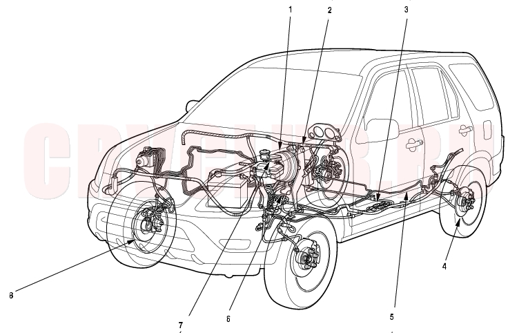
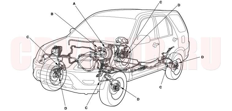
Component Location Index19A-3
Brake Booster Inspection, page 19A-27 ; Brake Booster Replacement, page 19A-29 Brake Pedal and Brake Pedal Position Switch Adjustement, page 19A-5 Parking Brake Cable Replacement, page 19A-42 Rear Brake Pads Inspection and Replacement, page 19A-30 ; Rear Brake Disc Inspection, page 19A-32 ; Rear Brake Caliper Overhaul, page 19A-33 ; Parking Brake Drum Inspection, page 19A-34 ; Parking Brake Shoes Replacement, page 19A-36 ; Lining Surface Break-in, page 19A-39 Brake Hoses and Lines Inspection, page 19A-40 ; Break Hoses Replacement, page 19A-41 Parking Brake Check and Adjustment, page 19A-6 ; Parking Brake Switch Test, page 19A-11 ; Brake System Indicator Circuit Diagram, page 19A-10 Brake Fluid Level Switch Test, page 19A-11 ; Master Cylinder Replacement, page 19A-21 ; Disassembly, page 19A-22 ; Reassembly, page 19A-23 ; Brake Booster Pushrod Clearance Adjustment, page 19A-26 ; Brake System Bleeding, page 19A-9 Front Brake Pads, Inspection and Replacement, page 19A-12 ; Front Brake Disc Inspection, page 19A-18 ; Front Brake Caliper Overhaul, page 19A-19
Brake System Operation and Leakage Check19A-4
Brake Pedal and Brake Pedal Position Switch Adjustment19A-5
Pedal Height
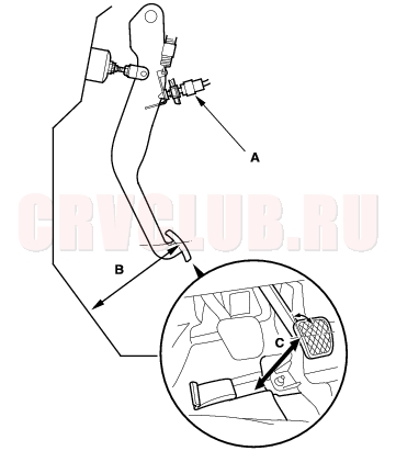
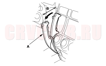
- Turn the brake pedal position switch (A) counterclockwise, and pull it back until it is no longer touching the brake pedal.
- Lift up the carpet. At the insulator cutout, measure the pedal height (B) from the middle of the pedal pad (C).
Standard Pedal Height (with carpet removed):
173 mm (6.81 in.) Min.
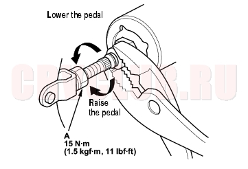
- Loosen the pushrod locknut (A), and screw the pushrod in or out with pliers until the standard pedal height from the floor is reached. After adjustment, tighten the locknut firmly. Do not adjust the pedal height with the pushrod pressed.
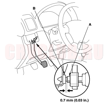
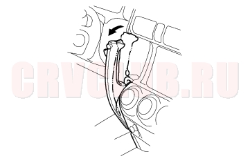
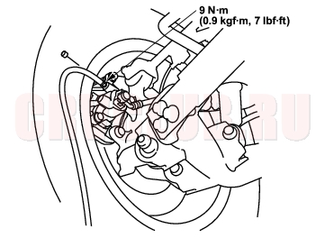
- Push in the brake pedal position switch until its plunger is fully pressed (threaded end (A) touching the pad (B) on the pedal arm). Then, turn the switch 45° clockwise to lock it. The gap between the brake pedal position switch and the pad is automatically adjusted to 0.7 mm (0.03 in.) by locking the switch. Make sure the brake lights go off when the pedal is released.
5. Check the brake pedal free play as described below.
Brake Pedal and Brake Pedal Position Switch Adjustment (cont'd)19A-6
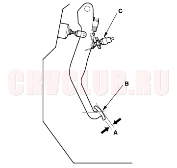
Pedal Free Play
Free Play: 1 - 5 mm (0.04 - 0.2 in.)
- If the pedal free play is out of specification, adjust the brake pedal position switch (C). If the pedal free play is insufficient, it may result in brake drag.
Parking Brake Check and Adjustment19A-6
Check
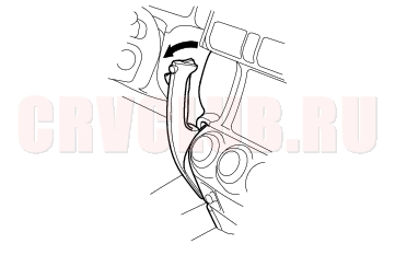
- Pull the parking brake lever (A) with 196 N (20 kgf, 44 lbf) of force to fully apply the parking brake. The parking brake lever should be locked within the specified number of clicks (B).
Lever locked clicks: 5 - 9
NOTE: Minor parking brake lever adjustments (1 - 2 clicks) can be made with the adjusting nut in the equalizer.
If a larger adjustment is required, follow the major adjustment procedure using the adjuster at the parking brake drum.
After installing new parking brake shoes and/or new rear brake disc/drums, make sure you to drive the vehicle for ''break-in'' (see page 19A-39) .
19A-7
Minor adjustment
- Raise the rear of the vehicle, and make sure it is securely supported.
- Release the parking brake lever fully. Move the driver's seat (RHD: assistant seat) all the way forward.
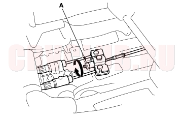
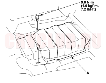
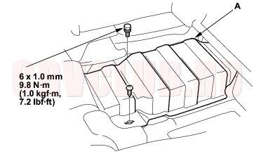
- Pull back the carpet under the seat. Remove the screw and bolt for the parking brake equalizer cover (A).
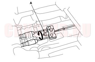
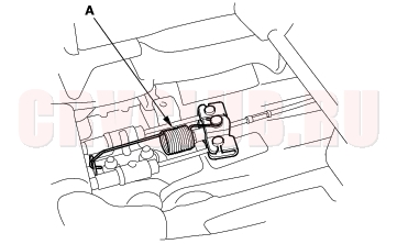
- Remove the return spring (A).
- Pull the parking brake lever one click.
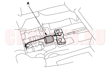
- Tighten the adjusting nut (A) until the parking brakes drag slightly when the rear wheels are turned.
- Release the parking brake lever fully, and check that the parking brakes do not drag when the rear wheels are turned. Readjust if necessary.
- Reinstall the return spring and the parking brake equalizer cover.
- Make sure the parking brakes are fully applied when the parking brake lever is pulled all the way.
Parking Brake Check and Adjustment (cont'd)19A-8
Major adjustment (to be done when replacing brake shoes and after lining surface break-in)
- Raise the rear of the vehicle, and make sure it is securely supported.
- Release the parking brake lever fully. Move the driver's seat (RHD: assistant seat) all the way forward.
- Pull back the carpet on the floor at the under the seat. Remove the screw and bolt for the parking brake equalizer cover (A).
- Remove the return spring (A).
- Back off the adjusting nut (A) in the equalizer.
- Remove the rear wheels.
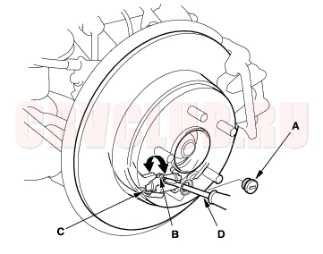
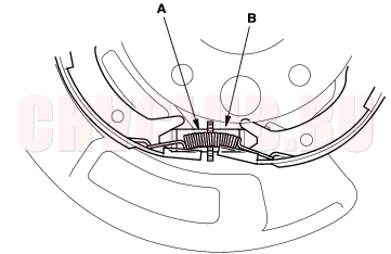
- Remove the access plug (A).
- Turn the ratchet teeth (B) on the adjuster assembly (C) with a flat-tip screwdriver (D) until the shoes lock against the drum. Then back off eight clicks, and install the access plug.
- Do the minor adjustment procedure.
- Install the rear wheels.
Brake System Bleeding19A-9
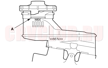
Do not spill brake fluid on the vehicle; it may damage the paint; if brake fluid does contact the paint, wash it off immediately with water. The reservoir on the master cylinder must be at the MAX (upper) level mark at the start of the bleeding procedure and checked after bleeding each brake caliper. Add fluid as required. Do not reuse the drained fluid. Always use Genuine Honda DOT 3 brake fluid. Non-Honda brake fluid can cause corrosion and shorten the life of the system. Make sure no dirt or other foreign matter is allowed to contaminate the brake fluid.
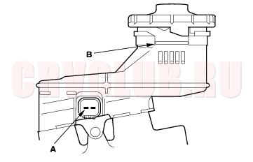
- Make sure the brake fluid level in the reservoir is at the MAX (upper) level line (A).
- Slide a piece of clear plastic hose over the first bleed screw, and submerge the other end in a container of new brake fluid.
- Have someone slowly pump the brake pedal several times, then apply steady pressure.
- Loosen the left-front brake bleed screw to allow air to escape from the system. Then tighten the bleed screw securely.
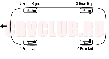
- Repeat the procedure for each wheel in the sequence shown below until air bubbles no longer appear in the fluid.
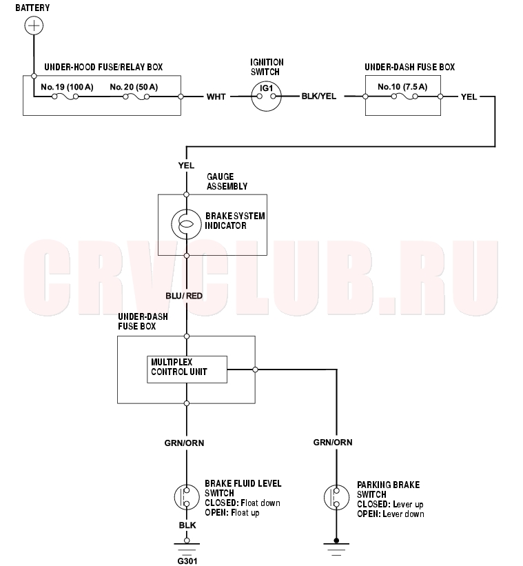
Brake System Indicator Circuit Diagram19A-10
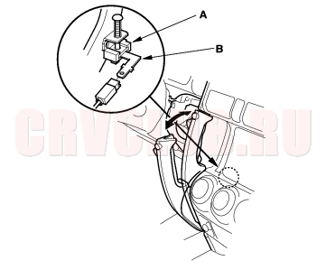
Parking Brake Switch Test19A-11
- Remove the driver's under panel (see page 20-89) .
- Disconnect the connector from the parking brake switch (A).
- Check for continuity between the switch terminal (B) and body ground:
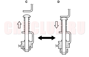
- With the parking brake lever pulled (C), there should be continuity.
- With the parking brake lever released (D), there should be no continuity.
If both the ABS indicator and the brake system indicator come on at the same time, check the ABS (see page 19B-3) . If the parking brake switch/brake fluid level switch is OK, but the brake system indicator does not work, check the ABS.
Brake Fluid Level Switch Test19A-11
Check for continuity between the terminals (A) with the float in the down position and the up position.
Remove the brake fluid completely from the reservoir. With the float down, there should be continuity. Fill the reservoir with brake fluid to MAX (upper) level (B). With the float up, there should be no continuity.
Front Brake Pads Inspection and Replacement19A-12
Inspection
- Raise the front of the vehicle, and make sure it is securely supported. Remove the front wheels.
- Check the thickness of the inner pad (A) and outer pad (B). Do not include the thickness of the brake pad backing plate.
Brake pad thickness:
Standard: 10.5 - 11.5 mm (0.41 - 0.45 in.)
Service Limit: 1.6 mm (0.06 in.)
Replacement (15 inch Brake Disc Type)
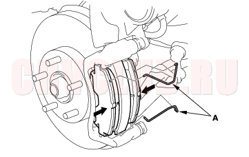
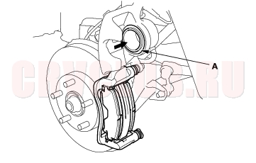
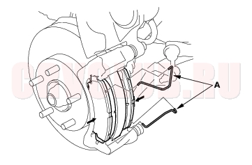
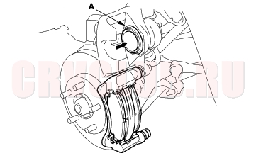
NOTE: The pad springs are installed on the pads to prevent brake drag. Be careful when pivoting up the caliper body fully, or the spring could be flipped out of the position.
- Pivot the caliper body slightly so the pads do not come out of position, and hold the pads on both sides firmly with your fingers. Remove the pad springs (A) from the pads.
19A-13
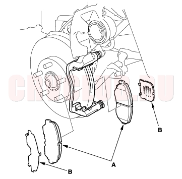
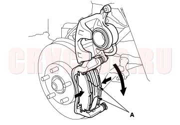
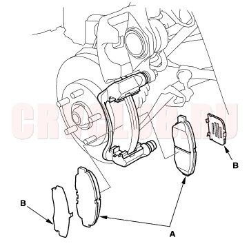
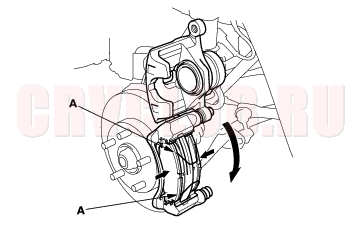
- Pivot up the caliper up out of the way and remove the pads (A).
- Remove the pad shims (B).
- Check the hose and pin boots for damage and deterioration.
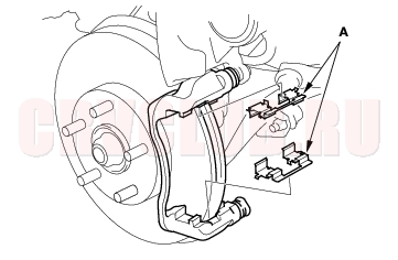
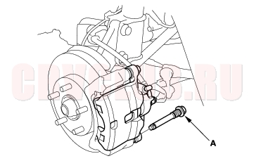
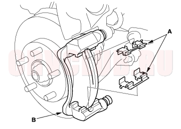
- Remove the pad retainers (A).
- Clean the caliper thoroughly; remove any rust, and check for grooves and cracks.
- Check the brake disc for damage and cracks.
- Install the pad retainers.
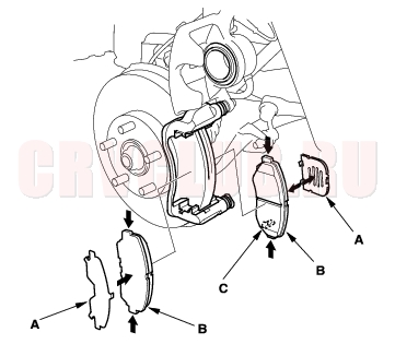
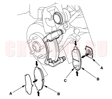
- Apply Dow Corning Molykote M77 grease to the back of the pads (B), and the other areas indicated by the arrows.
Wipe excess grease off the shim. Contaminated brake discs and pads reduce stopping ability. Keep grease off the discs and pads.
- Install the brake pads and pad shim correctly. Install the pads with the wear indicators (C) on the inside.
If you are reusing the pads, always reinstall the brake pads in their original positions to prevent a momentary loss of braking efficiency.
Front Brake Pads Inspection and Replacement (cont'd)19A-14
- Push in the piston (A) so the caliper will fit over the pads. Check the brake fluid level. The brake fluid may overflow if the reservoir is too full. Make sure the piston boot is in position to prevent damaging it when pivoting the caliper down.
- Hold the pads on both sides firmly with your fingers, and install the new pad springs (A) on the pads.
Holding the pads, set the caliper over the pads by pivoting it down slowly.
- NOTE: Insert the pad spring ends into the pad installation holes securely.
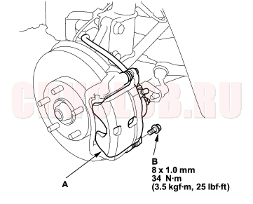
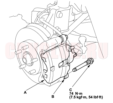
- Pivot the caliper (A) down into position. Be careful not to damage the pin boots.
- Install the flange bolt (B), and tighten it to the specified torque.
- Press the brake pedal several times to make sure the brake works, then test-drive.
- NOTE: Engagement of the brake may require a greater pedal stroke immediately after the brake pads have been replaced as a set. Several applications of the brake pedal will restore the normal pedal stroke.
- After installation, check for leaks at hose and line joints or connections, and retighten if necessary.
19A-15
Replacement (14 inch Brake Disc Type)
NOTE: The pad springs are installed on the pads to prevent brake drag. Be careful when pivoting up the caliper body fully, or the spring could be flipped out of the position.
- Pivot the caliper body slightly so the pads do not come out of position, and hold the pads on both sides firmly with your fingers. Remove the pad spring (A) from the pads.
- Pivot up the caliper up out of the way and remove the pad (A).
- Remove the pad shims (B).
- Check the hose and pin boots for damage and deterioration.
- Remove the pad retainers (A).
- Clean the caliper thoroughly; remvoe any rust, and check for grooves and cracks.
- Check the brake disc for damage and cracks.
- Install the pad retainers.
Front Brake Pads Inspection and Replacement (cont'd)19A-16
- Apply Dow Corning Molykote M77 grease to the back of the pads (B), and the other areas indicated by the arrows.
Wipe excess grease off the shim. Contaminated brake discs and pads reduce stopping ability. Keep grease off the discs and pads.
- Install the brake pads and pad shim correctly. Install the pads with the wear indicators (C) on the inside.
If you are reusing the pads, always reinstall the brake pads in their original positions to prevent a momentary loss of braking efficiency.
- Push in the piston (A) so the caliper will fit over the pads. Check the brake fluid level. The brake fluid may overflow if the reservoir is too full. Make sure the piston boot is in position to prevent damaging it when pivoting the caliper down.
- Hold the pads on both sides firmly with your fingers, and install the new pad springs (A) on the pads. Holding the pads, set the caliper body over the pads by pivoting it down slowly.
- NOTE: Insert the pad spring ends into the pad installation holes securely.
19A-17
- Pivot the cliper (A) down into position. Be careful not to damage the pin boot (B), and check for the pin boot are not deformed or removed.
- Install the pin bolt (C), and tighten it to the specified torque.
- Press the brake pedal several times to make sure the brake works, then test-drive.
- NOTE: Engagement of the brake may require a greater pedal stroke immediately after the brake pads have been replaced as a set. Several applications of the brake pedal will restore the normal pedal stroke.
- After installation, check for leaks at hose and line joints or connections, and retighten if necessary.
Front Brake Disc Inspection19A-18
Runout
- Raise the front of the vehicle, and make sure it is securely supported. Remove the front wheels.
- Remove the brake pads (see page 19A-12) .
- Inspect the disc surface for damage and cracks. Clean the disc thoroughly, and remove all rust.
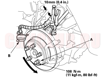
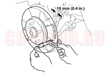
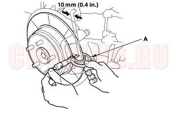
- Install suitable flat washers (A) and wheel nuts, and tighten the nuts to the specified torque to hold the brake disc securely against the hub.
- Set up the dial gauge against the brake disc as shown, and measure the runout at 10 mm (0.4 in.) from the outer edge of the disc.
Brake Disc Runout:
Service Limit: 0.10 mm (0.004 in.)
Max. Refinish Limit: 21.0mm (0.83 in.)
NOTE: If the brake disc is beyond the service limit for refinishing, replace it (see page 18-12) . A new disc should be refinished if its runout is greater than 0.10 mm (0.004 in.). Thickness and Parallelism
- Raise the front of the vehicle, and make sure it is securely supported. Remove the front wheels.
- Remove the brake pads (see page 19A-12) .
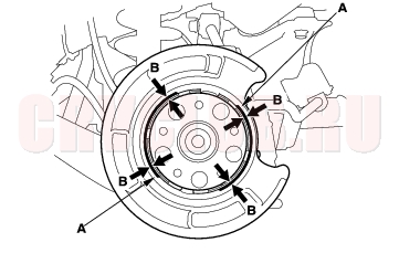
- Using a micrometer, measure disc thickness at eight points, approximately 45° apart and 10 mm (0.4 in.) in from the outer edge of the disc.
- NOTE: This is the maximum allowable difference between the thickness measurements.
Brake Disc Thickness:
Standard: 23.0 mm(0.91 in.)
Max. Refinishing Limit: 21.0 mm (0.83 in.)
Brake Disc Parallelism: 0.015 mm (0.0006 in.) max.
- If the smallest measurement is less than the max. Refinishing limit, replace the brake disc (see page 18-12) .
- If the disc is beyond the service limit for parallelism, refinish the brake disc with an on-car brake lathe.
The Kwik-Lathe produced by Kwik-way Manufacturing Co. and the ''Front Brake Disc Lathe'' offered by Snap-on Tools Co. are approved for this operation.
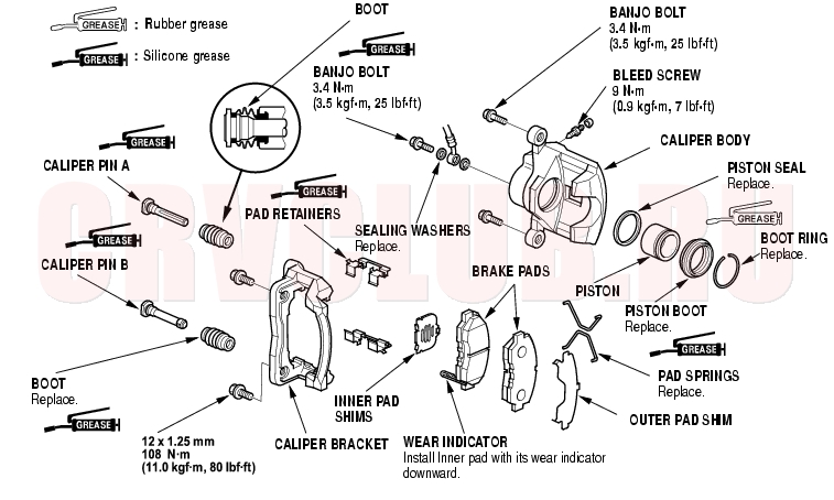
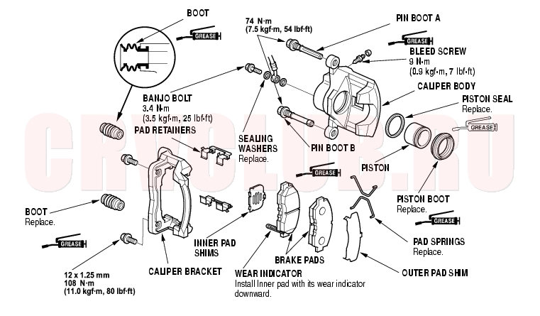
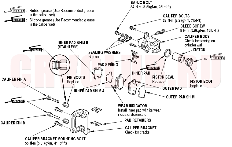
Front Brake Caliper Overhaul19A-19
Remove, disassemble, inspect, reassemble, and install the caliper, and note these items:
Do not spill brake fluid on the vehicle; it may damage the paint; if brake fluid gets on the paint, wash it off immediately with water. To prevent dripping, cover disconnected hose joints with rags or shop towels. Clean all parts in brake fluid and air dry; blow out all passages with compressed air. Before reassembling, check that all parts are free of dust and other foreign particles. Replace parts with new ones as specified in the illustration. Make sure no dirt or other foreign matter is allowed to contaminate the brake fluid. When reusing pads, always reinstall them in their original positions to prevent loss of braking efficiency. Do not reuse drained brake fluid. Always use Genuine Honda DOT 3 brake fluid. Non-Honda brake fluid can cause corrosion and shorten the life of the system. Do not mix different brands of brake fluid as they may not be compatible. Coat the piston, piston seal groove, and caliper bore with clean brake fluid. Make sure no grease or oil gets on the brake discs or pads. Replace all rubber parts with new ones whenever disassembled. After installing the caliper, check the brake hose and line for leaks, interference, and twisting. Front Brake Caliper Overhaul (cont'd)19A-20
15 inch Brake Disc Type (AD57-15):
14 inch Brake Disc Type (AD57-14):
Master Cylinder Replacement19A-21
NOTE: Do not spill brake fluid on the vehicle; it may damage the paint; if brake fluid does contact the paint, wash it off immediately with water.
- Release the engine wire harness clips on the strut brace (A), and remove the strut brace. With M/T: Remove the clutch reservoir bracket from the strut brace, and move it aside. Do not disconnect the clutch hose from the reservoir.
- Remove the reservoir cap and brake fluid from the master cylinder reservoir.
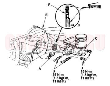
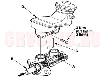
- Remove the brake fluid level sensor connector (A).
- Disconnect the brake lines (B) from the master cylinder (C). To prevent spills, cover the hose joints with rags or shop towels.
- Remove the master cylinder mounting nuts (D) and washers.
- Remove the master cylinder from the brake booster (E). Be careful not to bend or damage the brake lines when removing the master cylinder.
- Remove the rod seal (F) from the master cylinder.
- Install the master cylinder in the reverse order of removal, and note these items:
- Replace all the rubber parts with new ones whenever the master cylinder is removed.
- Check the pushrod clearance before installing the master cylinder, and adjust it if necessary (see page 19A-26) .
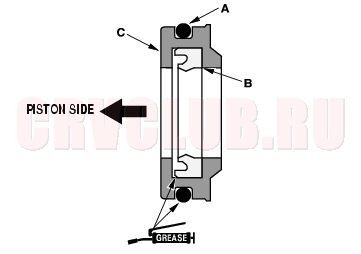
- Use a new rod seal on reassembly.
- Coat the inner bore lip and outer circumference of the new rod seal with the recommended seal grease in the master cylinder set.
- Install the rod seal onto the master cylinder with its grooved side (G) toward the master cylinder.
- Check the brake pedal height and free play after installing the master cylinder, and adjust it if necessary (see page 19A-5) .
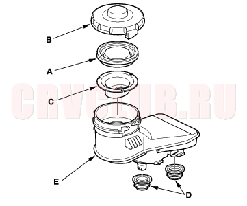
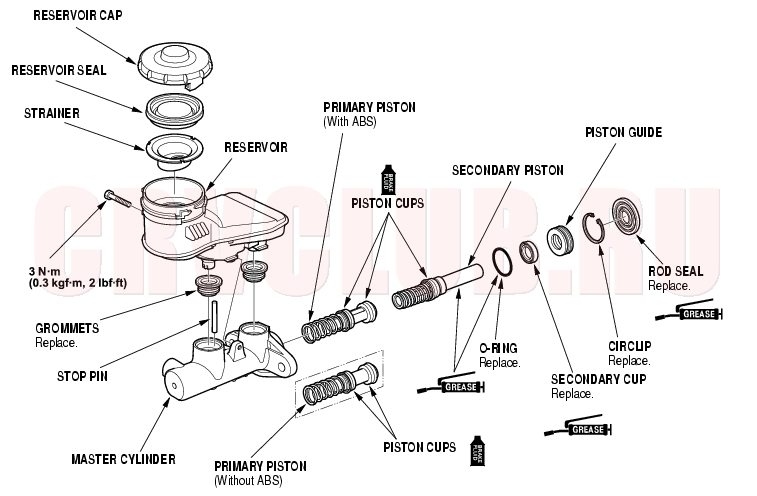
Master Cylinder Disassembly19A-22
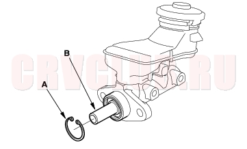
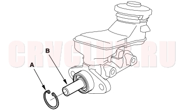
- Remove the rod seal from the master cylinder.
- Remove the circlip (A) while pushing in the secondary piston (B).
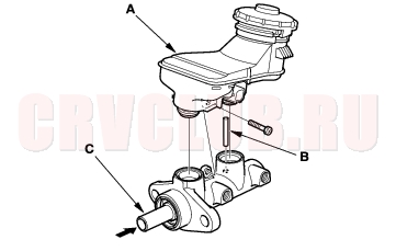
- Remove the reservoir (A).
- On vehicle's with ABS; remove the stop pin (B) while pushing in the secondary piston (C).
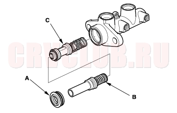
- Remove the piston guide (A), secondary piston (B) and primary piston (C).
- Remove the reservoir seal (A) from the reservoir cap (B).
- Remove the strainer(C) and grommets (D) from the reservoir (E).
NOTE: When reservoir and master cylinder body are separated, replace the grommets with new ones.
Master Cylinder Reassembly19A-23
If replacing the primary piston, secondary piston, or master cylinder body, check and adjust the pushrod clearance (see page 19A-26) before installing the master cylinder. Clean all the parts in brake fluid and air dry; blow out all passages with compressed air. Before reassembling, check that all the parts are free of dust and other foreign particles. Replace parts with new ones whenever specified to do so. Use only genuine DOT3 Honda brake fluid. Non-Honda brake fluid can cause corrosion and shorten the life of the system. Do not mix different brands of brake fluid as they may no be compatible. Replace the master cylinder if the bore is damaged or worn. Do not hone or attempt to refinish the bore. Coat the piston cups, pressure cup and master cylinder bore with clean brake fluid. Use recommended greases in the master cylinder seal set.
- Install the reservoir seal in the groove of the reservoir cap.
- Install the strainer, assembled reservoir cap, and new grommets on the reservoir.
Master Cylinder Reassembly (cont'd)19A-24
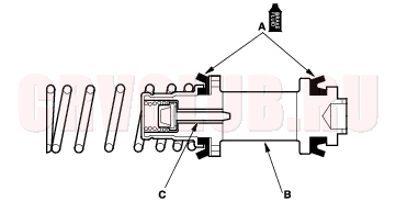
- Coat the cups (A) of a new primary piston (B) with clean brake fluid, then install the primary piston into the master cylinder.
- NOTE: On vehicle's with ABS, check that the valve stem (C) moves smoothly by lightly pushing it through the slot in the piston. Install the piston so the slot in the piston aligns with the stop pin hole in the master cylinder.
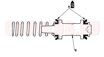
- Coat the cup (A) of a new secondary piston (B) with clean brake fluid.
- Apply recommended seal grease in the master cylinder seal set to the piston surface (C), then install the secondary piston into the master cylinder.
- Apply recommended seal grease in the master cylinder seal set to a new O-ring (A) and the secondary cup (B) in a new piston guide (C), then install the piston guide into the master cylinder. Note the direction.
19A-25
- On vehicle's with ABS; align the slot in the primary piston with the stop pin hole (A) by pushing the secondary piston (B) in, and install the stop pin (C).
- Install the reservoir (D) to the master cylinder.
- Install the new circlip (A) while pushing in the secondary piston (B). Be careful not to scratched damage on the piston surface with the circlip edges.
- Adjust the pushrod clearance (see page 19A-26) .
- Apply recommended seal grease in the master cylinder seal set to a new rod seal, and install the seal onto the master cylinder (see page 19A-21) .
Brake Booster Pushrod Clearance Adjustment19A-26
Special Tools Required
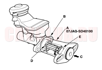
Pushrod adjustment gauge 07JAG-SD40100 Vacuum gauge 07404-5790301 Tube joint adapter 07410-5790501 NOTE: Master cylinder pushrod-to-piston clearance must be checked and adjustments made, if necessary, before installing the master cylinder.
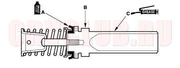
- Set the special tool (A) on the master cylinder body (B), push in the center shaft (C) until the top (D) of it contacts the end of the secondary piston (E) by turning the adjusting nut (F).
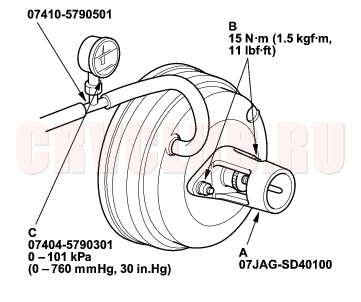
- Without disturbing the center shaft's position, install the special tool (A) backwards on the booster.
- Install the master cylinder nuts (B), and tighten to the specified torque.
- Connect the booster in-line with a vacuum gauge (C) 0 - 101 kPa (0 - 760 mmHg, 30 in.Hg) to the booster's engine vacuum supply, and maintain an engine speed that will deliver 66 kPa (500 mmHg, 20 in.Hg) vacuum.
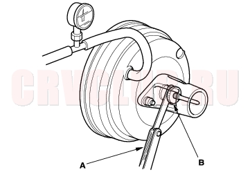
- With a feeler gauge (A), measure the clearance between the gauge body and the adjusting nut (B) as shown.
If the clearance between the gauge body and adjusting nut is 0.4 mm (0.02 in.), the pushrod-to-piston clearance is 0 mm. However, if the clearance between the gauge body, and adjusting nut is 0 mm, the pushrod-to-piston clearance is 0.4 mm (0.02 in.) or more. Therefore it must be adjusted and rechecked.
Clearance: 0 - 0.4 mm (0 - 0.02 in.)
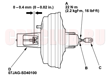
- If the clearance is incorrect, loosen the star locknut (A) and turn the adjuster (B) in or out to adjust.
- Adjust the clearance while the specified vacuum is applied to the booster.
- Hold the clevis (C) while adjusting.
- Tighten the star locknut securely.
- Remove the special tool (D).
19A-27
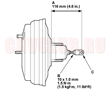
- Check the pushrod length (A) as shown if the booster is removed. If the length is incorrect, loosen the pushrod locknut (B), and turn the clevis (C) in or out to adjust.
- Install the master cylinder (see page 19A-21) .
Brake Booster Inspection19A-27
Special Tools Required
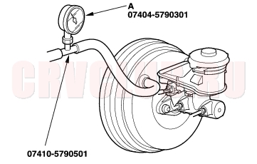
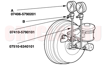
Vacuum gauge 07404-5790301 Pressure gauge 07406-5790201 Attachment 07410-5790101 Tube joint adapter 07410-5790501 Pressure gauge joint pipe 07510-6340101 Leak Test
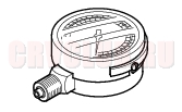
- Install the vacuum gauge (A) between the brake booster and check valve.
- Start the engine, adjust the engine speed with the accelerator pedal so that the vacuum gauge readings show 40.0 - 66.7 kPa (300 - 500 mmHg, 11.8 - 19.7 in.Hg), then stop the engine.
- Read the vacuum gauge.
If the vacuum reading decreases 2.7 kPa (20 mmHg, 0.8 in.Hg) or more after 30 seconds, check following parts for leaks.
Check valve Vacuum hose, pipe Seals Brake booster Master cylinder NOTE: Do not try to disassemble the brake booster. Replace the brake booster as an assembly with a new one. Brake Booster Inspection (cont'd)19A-28
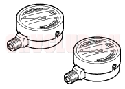
Function Test
- Install the vacuum gauge as same as the leak test.
- Connect the oil pressure gauges (A) to the master cylinder using the attachments (special tools) as shown.
- Bleed air through the valves (B).
- Start the engine and let it idle.
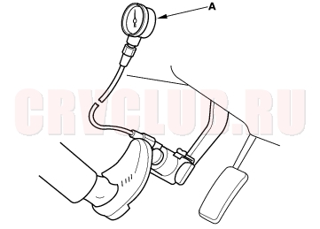
- Have an assistant depress the brake pedal with a 98 N (10 kgf, 22 lbf) and 294 N (30 kgf, 66 lbf) of pressure measuring with a commerciallly available pressure gauge (A).
- The following pressures should be obseved at the pressure gauges in each vacuum.
Booster Check Valve Test
- Disconnect the brake booster vacuum hose (check valve built in) (A) at the booster side.
- Start the engine, and let it idle. There should be vacuum available. If no vacuum is available, the check valve is not working properly. Replace the brake booster vacuum hose and check valve, and retest.
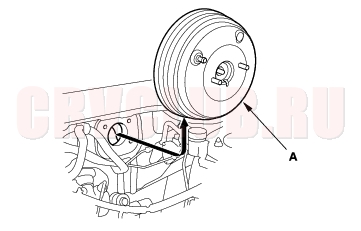
Brake Booster Replacement19A-29
- Remove the master cylinder (see page 19A-21) .
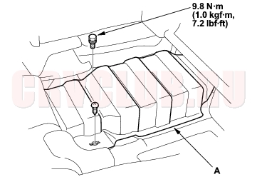
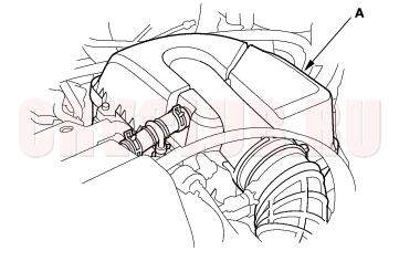
- Remove the air cleaner assembly (A).
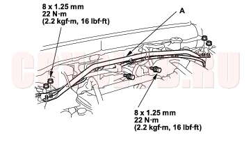
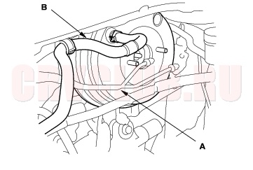
- Remove the master cylinder brake lines (A) from the brake line clip.
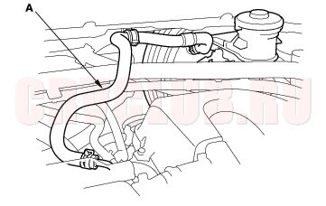
- Disconnect the vacuum hose (B) from the brake booster.
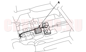
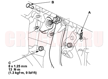
- Remove the clip (A) and the joint pin (B), and disconnect the yoke from the brake pedal.
- Remove the brake booster mounting nuts (C).
- Remove the brake booster (A) from the engine compartment.
NOTICE
Be careful not to damage the booster surfaces and threads of the booster stud bolts. Be careful not to bent or damage the brake lines.
- Install the brake booster in the reverse order of removal, and note these items:
- Adjust the pushrod clearance before installing the brake booster (see page 19A-26) .
- Use a new clip whenever installing.
- After installing the brake booster and master cylinder, fill the reservoir with new brake fluid, bleed the brake system (see page 19A-9) , and adjust the brake pedal height and free play (see page 19A-5) .
Rear Brake Pads Inspection and Replacement19A-30
Inspection
- Raise the rear of the vehicle, and make sure it is securely supported. Remove the rear wheels.
- Check the thickness of the inner (A) and outer pads (B). Do not include the thickness of the brake pad backing plate.
Brake pad thickness
Standard: 8.5 - 9.5 mm (0.33 - 0.37 in.)
Service limit: 1.6 mm (0.06 in.)
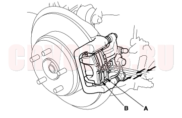
Replacement
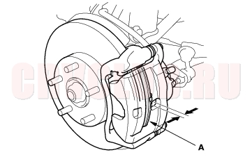
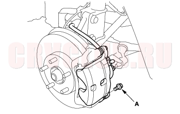
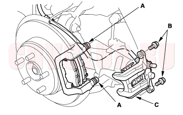
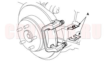
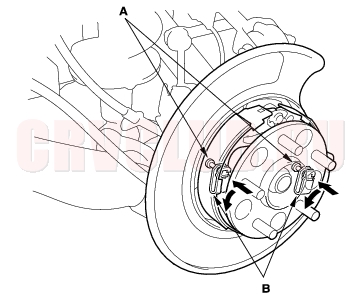
- Hold the pins (A) with a wrench, being careful not to damage the pin boots. Remove the caliper bolts (B) and remove the caliper (C) from the caliper bracket.
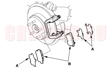
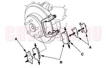
- Remove the pad shims (A) and pads (B).
19A-31
- Remove the pad retainers (A).
- Clean the caliper thoroughly; remove any rust, and check for grooves and cracks.
- Check the brake disc for damage and cracks.
- Install the pad retainers.
- Apply Dow Corning Molykote M77 grease to both sides of the pad shims (A), the back of the pads (B), and the other areas indicated by the arrows. Wipe excess grease off the shim. Contaminated brake discs and pads reduce stopping ability. Keep grease off the discs and pads.
- Install the brake pads and pad shims correctly. Install the pads with the wear indicators (C) on the inside.
If you are reusing the pads, always reinstall the brake pads in their original positions to prevent a momentary loss of braking efficiency.
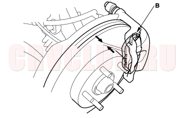
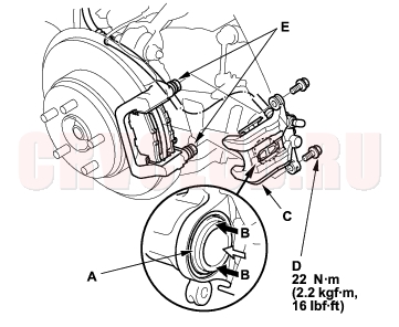
- Push in the piston (A) so that the caliper will fit over the pads.Check the brake fluid level. The brake fluid may overflow if the reservoir is too full. Make sure that the piston boot is in position to prevent damaging it when installing the caliper.
- Apply Dow Corning Molykote M77 grease to the piston edges (B) on their mating surfaces against the inner pad shim.
- Install the brake caliper (C) and caliper bolts (D), and torque them to the specified torque while holding the pin (E). Be careful not to damage the pin boots.
- Press the brake pedal several times to make sure the brake works then test-drive.
- NOTE: Engagement of the brake may require a greeter pedal stroke immediately after the brake pads have been replaced as a set. Several applications of the brake pedal will restore the normal pedal stroke.
- After installation, check for leaks at hose and line joints or connections, and retighten if necessary.
Rear Brake Disc Inspection19A-32
Runout
- Raise the rear of the vehicle, and make sure it is securely supported. Remove the rear wheels.
- Remove the brake pads (see page 19A-30) .
- Inspect the disc surface for damage and cracks. Clean the disc thoroughly and remove all rust.
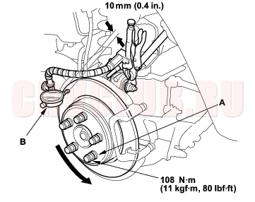
- Use wheel nuts and suitable flat washers (A) to hold the disc securely against the hub, then mount a dial indicator (B) as shown, and measure the runout at 10 mm (0.4 in.) from the outer edge of the disc.
Brake Disc Runout:
Service limit: 0.10 mm (0.004 in.)
Max. Refinishing Limit: 8.0 mm (0.31 in.)
NOTE: A new disc should be refinished if its runout is greater than 0.10 mm (0.004 in.). Thickness and parallelism
- Loosen the rear wheel nuts slightly, then raise the vehicle and make sure it is securely supported. Remove the rear wheels.
- Remove the brake pads (see page 19A-30) .
- Using a micrometer (A), measure disc thickness at eight points, approximately 45° apart and 10 mm (0.4 in.) in from the outer edge of the disc.
This is the maximum allowable difference between the thickness measurements.
Brake Disc thickness:
Standard: 8.9 - 9.1 mm (0.350 - 0.358 in.)
Max. Refinishing Limit: 8.0 mm (0.31 in.)
Brake Disc Parallelism: 0.015 mm
(0.0006 in.) max.
- If the smallest measurement is less than the max. Refinishing limit, replace the brake disc (see page 18-27) .
- If the disc is beyond the service limit for parallelism, refinish the brake disc with an on-car brake lathe. The Kwik-Lathe produced by Kwik-way Manufacturing Co. and the ''Front Brake Disc Lathe'' offered by Snap-on Tools Co. are approved for this operation.
Rear Brake Caliper Overhaul19A-33
Remove, disassemble, inspect, reassemble, and install the caliper, and note these items:
Do not spill brake fluid on the vehicle; it may damage the paint; if brake fluid gets on the paint, wash it off immediately with water. Clean all parts in brake fluid and air dry; blow out all passages with compressed air. Before reassembling, check that all parts are free of dirt and other foreign particles. Replace parts with new ones as specified in the illustration. Make sure no dirt or other foreign matter gets in the brake fluid. Make sure no grease or oil gets on the brake discs or pads. When reusing pads, always reinstall them in their original positions to prevent loss of braking efficiency. Do not reuse drained brake fluid. Always use Genuine Honda DOT 3 Brake Fluid. Non-Honda brake fluid can cause corrosion and shorten the life of the system. Coat the piston, piston seal groove, and caliper bore with clean brake fluid. Replace all rubber parts with new ones. After installing the caliper, check the brake hose and line for leaks, interference, and twisting.
Parking Brake Drum Inspection19A-34
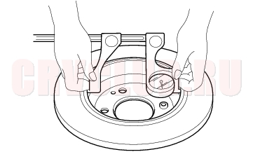
- Raise the rear of the vehicle, and make sure it is securely supported. Remove the rear wheels.
- Release the parking brake, and remove the rear brake caliper and disc/drum (see page 18-27) .
19A-35
- Check the parking brake linings (A) for cracking, glazing, wear, and contamination.
- Measure the parking brake lining thickness (B). Measurement does not include brake shoe thickness.
Parking brake lining thickness:
Standard: 3.2 mm (0.126 in.)
Service limit: 1.0 mm (0.04 in.)
- If the brake lining thickness is less than the service limit, replace all the parking brake shoes as a set.
- Check the bearings in the hub unit for smooth operation.
- Measure the inside diameter of the parking brake drum with inside vernier calipers.
Parking brake drum inside diameter:
Standard: 169.9 - 170.0 mm (6.689 - 6.693 in.)
Service limit: 171.0 mm (6.732 in.)
- If the inside diameter of the parking brake drum is more than service limit, replace the rear brake disc/drum.
- Check the parking brake drum for scoring, grooves, and cracks.
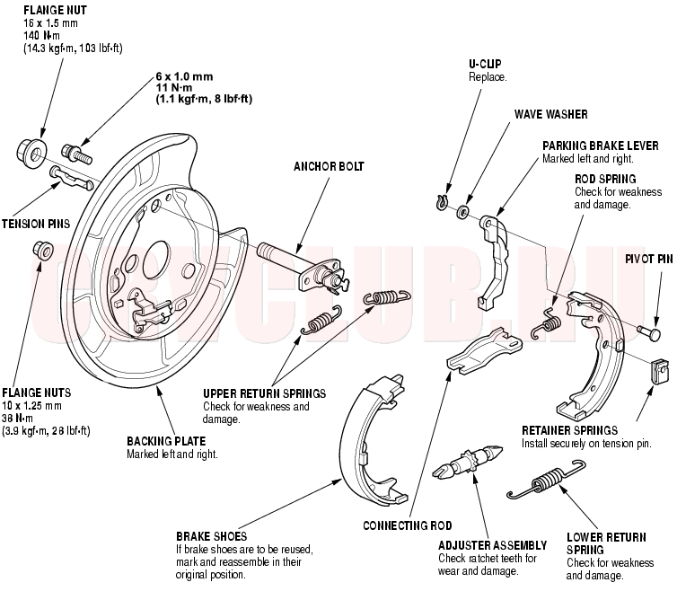
Parking Brake Shoes Replacement19A-36
Disassembly
- Raise the rear of the vehicle, and make sure it is securely supported. Remove the rear wheels.
- Release the parking brake and remove the rear brake caliper and brake disc/drum (see page 18-27) .
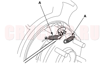
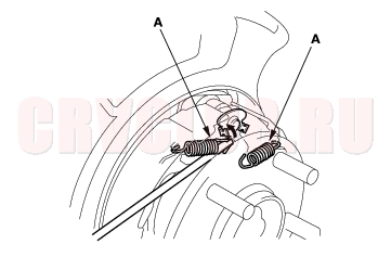
- Disconnect and remove the upper return springs (A).
- Remove the tension pins (A) by pushing the retainer springs (B) and turning the pins.
- Disconnect the rod spring (A), and remove the connecting rod (B).
- Lower the parking brake shoe assembly.
- Remove the forward brake shoe by removing the lower return spring (A) and adjuster assembly (B).
19A-37
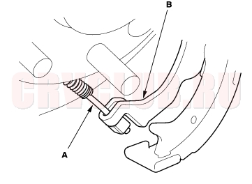
- Remove the rearward brake shoe by disconnecting the parking brake cable (A) from the parking brake lever (B).
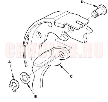
- Remove the U-clip (A), wave washer (B), parking brake lever (C) and pivot pin (D) from the brake shoe.
Reassembly
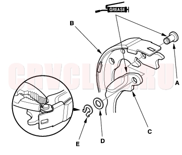
- Apply Molykote 44 MA grease to the sliding surface of the pivot pin (A), and insert the pin into the rearward brake shoe (B).
- Install the parking brake lever (C) and washer (D) on the pivot pin, and secure with a new U-clip (E).
- Install the wave washer with its convex side facing out.
- Pinch the U-clip securely to prevent the pivot pin from coming out from the brake shoe.
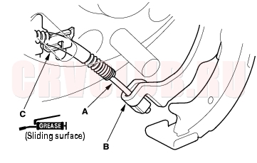
- Connect the parking brake cable (A) to the parking brake lever (B). Apply silicone grease to the cable contact surface (C) on the backing plate.
Parking Brake Shoes Replacement (cont'd)19A-38
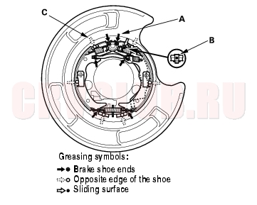
- Apply Molykote 44 MA grease to the shoe ends (A), sliding surfaces (B), and opposite edges of the parking brake shoe (C) as shown. Wipe off any excess. Don't get grease on the brake linings.
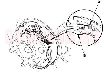
- Clean the threaded portions of the clevis (A), and coat the threads of the clevis with grease. Clean the sliding surface of the clevis (B), and coat the sliding surface of the clevis (B) with grease. Install the clevis (A) and (B) on the adjuster (C), and shorten the clevis (A) by turning the adjuster.
- Reinstall the brake shoe adjuster assembly (D), and hook the lower return spring (E) on the parking brake shoes.
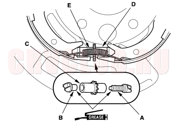
- Hook the rod spring (A) to the connecting rod (B) first with the spring end (C) pointing downward. Then hook the rod spring to the parking brake shoe, and install the connecting rod on the parking brake shoes.
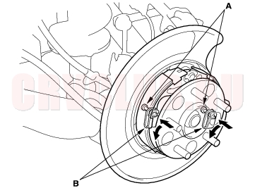
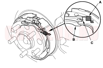
- Reinstall the tension pins (A) and retainer springs (B). Make sure the tension pin does not contact the parking brake lever.
19A-39
- Reinstall the upper return springs (A).
- Install the rear brake disc/drum and rear brake caliper (see page 18-28) .
- Do the major adjustment for parking brake (see page 19A-6) .
Lining Surface Break-in19A-39
NOTE:
Do brake linings surface break-in when replacing shoes with new linings and/or new rear brake disc/drum.
- Park the vehicle on a firm, level surface.
- Do the major parking brake adjustment.
- Do the minor parking brake adjustment.
- Drive the vehicle at no more than 31 mph
(50 km/h).
- Pull the parking brake lever two to four clicks while driving the vehicle for 400 m (1/4 mile).
- Stop the vehicle, and release the parking brake lever for 5 - 10 minutes to allow the drums to cool. Repeat steps 4 through 6 three more times.
- Do the major parking brake adjustment (see page 19A-6) .
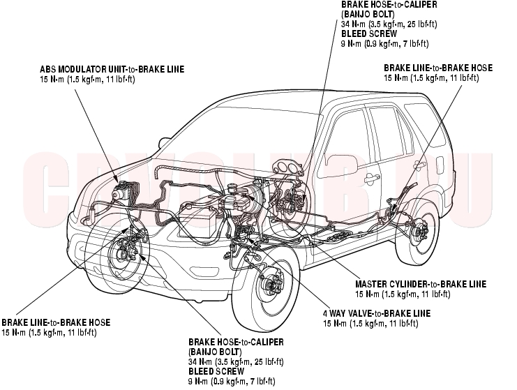
Brake Hoses and Lines Inspection19A-40
- Inspect the brake hoses, for damage, deterioration, leaks, interference, and twisting.
- Check the brake lines for damage, rusting, and leakage. Also check for bent brake lines.
- Check for leaks at hose and line joints or connections, and retighten if necessary.
- Check the master cylinder and ABS modulator unit (if equipped) for damage and leakage.
- NOTE: Replace the brake hose clip whenever the brake hose is serviced.
Brake Hose Replacement19A-41
Do not spill brake fluid on the vehicle; it may damage the paint; if brake fluid gets on the paint, wash it off immediately with water. To prevent dripping, cover disconnected line joints with rags or shop towels. Before reassembling, check that all parts are free of dust and other foreign particles. Replace parts with new ones whenever specified to do so.
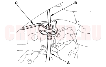
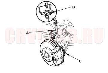
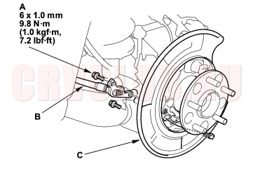
- Replace the brake hose (A) if the hose is twisted, cracked, or if it leaks.
- Disconnect the brake hose from the brake line (B) using a 10 mm flare nut wrench (C).
- Remove the flange bolt (A), and remove the brake hose brackets from the damper.
- Remove and discard the hose clip (B).
- Remove the banjo bolt (C), and remove the brake hose from the caliper.
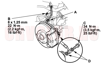
- Install the brake hose bracket (A) on the damper with the flange bolt (B) first, then connect the brake hose to the caliper with the banjo bolt (C) and new sealing washers (D).
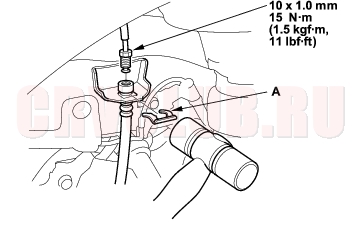
- Install the hose onto the hose bracket on the body with a new hose clip (A).
- Connect the brake line to the brake hose.
- After installing the brake hose, bleed the brake system (see page 19A-9) .
- Do the following checks:
- Check the brake hose and line joint for leaks, and tighten if necessary.
- Check the brake hoses for interference and twisting.
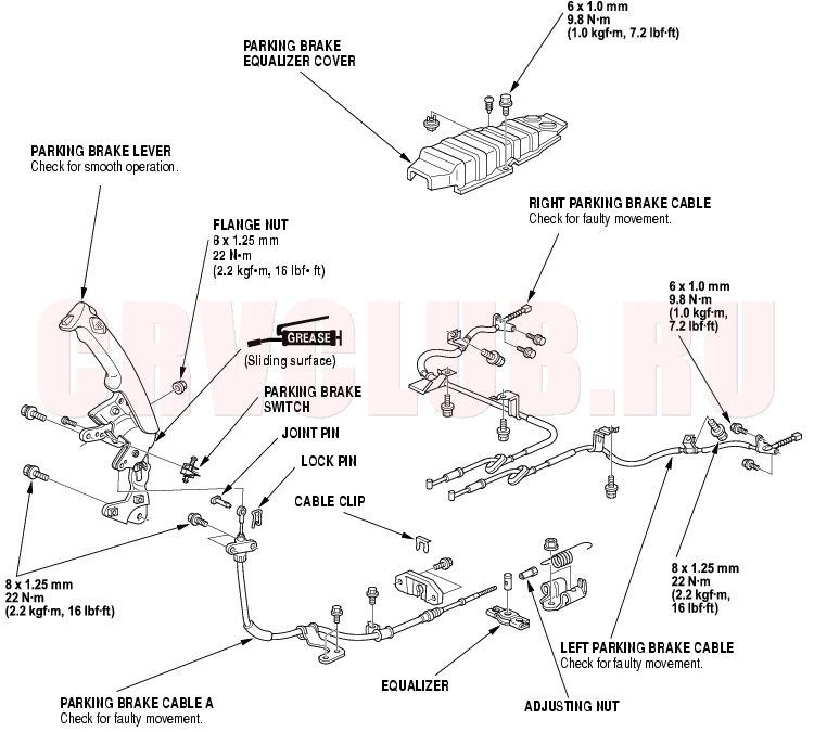
Parking Brake Cable Replacement19A-42
Exploded View
19A-43
The parking brake cables must not be bent or distorted. This will lead to stiff operation and premature failure. Refer to the Exploded View as needed during this procedure.
- Raise the rear of the vehicle, and make sure it is securely supported.
- Release the parking brake lever fully. Move the driver's seat (RHD: assistant seat) all the way forward.
- Pull back the carpet on the floor at the under the seat. Remove the screw and bolt for the parking brake equalizer cover (A).
- Remove the return spring (A).
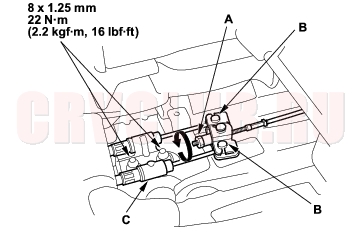
- Back off the adjusting nut (A) in the equalizer, and disconnect the parking brake cable ends (B) from the equalizer.
- Remove the cable guide base (C).
- Remove the rear brake shoes (see page 19A-36) , and disconnect the parking brake cable from the shoe.
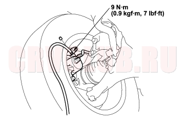
- Remove the flange bolts (A) and parking brake cable (B) from the backing plate (C).
- Reinstall the parking brake cable in revers order of removal, and note these item.
- Be careful not to bend or distort the cable.
- Do the major parking brake adjustment (see page 19A-6) .
|
Brakes19A-1
Conventional Brake Components19A-2 |