Intake Air System11-176
|
Fuel and Emissions11-1
Intake Air System11-176 |
Intake Air System11-176
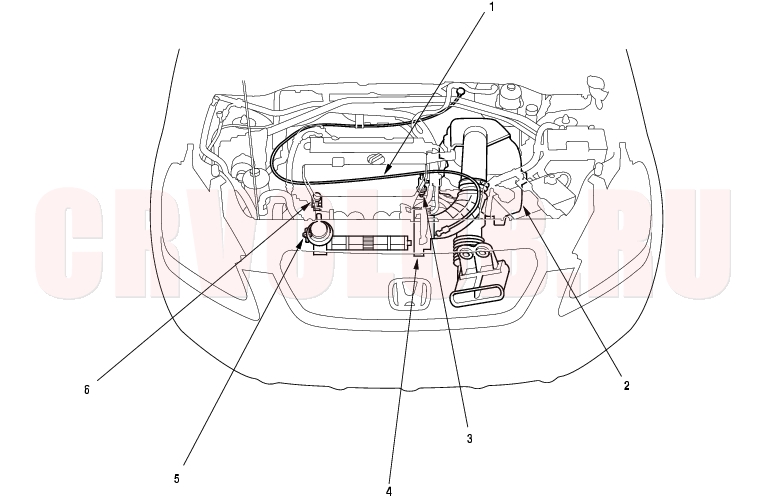
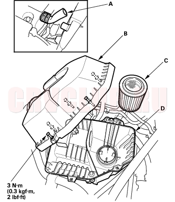
Component Location Index
*: The illustration shows LHD model.
Adjustment, page 11-183 ; Removal/Installation, page 11-184 Replacement, page 11-182 Replacement, page 11-182 Test, page 11-181 Test, page 11-180 ; Removal/Installation, page 11-185 ;
Disassembly/Reassembly, page 11-186Troubleshooting, page 11-177 ; Replacement, page 11-187 Troubleshooting, page 11-177
IMRC System Troubleshooting11-177
- Start the engine and allow it to idle.
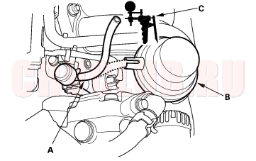
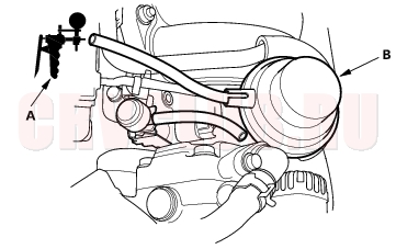
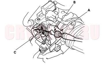
- Disconnect the vacuum hose (A) from Intake Manifold Runner Control (IMRC) actuator (B), and connect the vacuum pump/gauge (C) to the hose.
Is there vacuum?
Yes : Go to step 10.
No : Go to step 3.
Is there vacuum hose OK?
Yes : Go to step 4.
No : Repair the blockage or vacuum leak between the IMRC actuator and IMRC solenoid valve.

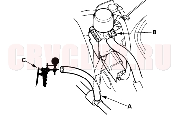
- Disconnect the lower vacuum hose (A) from IMRC solenoid valve (B), and connect the vacuum pump/gauge (C) to the hose.
Is there vacuum?
Yes : Go to step 5.
No : Repair the blockage or vacuum leak between the intake manifold and IMRC solenoid valve.
- Reconnect the lower vacuum hose to the IMRC solenoid valve, and connect the vacuum pump/gauge to the vacuum hose (actuator side).
- Disconnect the IMRC solenoid valve 2P connector.
Is there vacuum?
Yes : Go to step 7.
No : Replace the IMRC solenoid valve.
IMRC System Troubleshooting (cont'd)11-178
- Turn the ignition switch OFF.
- Disconnect the negative cable from the battery.
- Disconnect ECM/PCM connector B (24P).
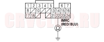
- Check for continuity between IMRC solenoid valve 2P connector terminal No. 2 and body ground.
Is there continuity?
Yes : Repair short in the wire between the ECM/PCM (B22) and the IMRC solenoid valve.
No : Substitute a known-good ECM/PCM and recheck (see page 11-5). If symptom/indication goes away, replace the original ECM/PCM.
Is there vacuum?
Yes : Go to step 13.
No : Go to step 23.
- Turn the ignition switch OFF.
- Disconnect the IMRC solenoid valve 2P connector.
- Start the engine.
- Raise engie speed to 5,000 rpm (min-1), then measure voltage between IMRC solenoid valve 2P connector terminal No. 1 and No. 2.
Is there battery voltage?
Yes : Replace the IMRC solenoid valve.
No : Go to step 17.
Is there battery voltage?
Yes : Go to step 18.
No : Check the No. 4 ACG (10A) fuse in the under-dash fuse/relay box. If the fuse OK, repair open in the wire between the IMRC solenoid valve and No. 4 ACG (10A) fuse.
11-179
- Turn the ignition switch OFF.
- Disconnect the negative cable from the battery.
- Disconnect ECM/PCM connector B (24P).
- Connect IMRC solenoid valve 2P connector terminal No. 2 to body ground with a jumper wire.
Is there continuity?
Yes : Substitute a known-good ECM/PCM and recheck (see page 11-5). If symptom/indication goes away, replace the original ECM/PCM.
No : Repair open in the wire between the ECM/PCM (B22) and the IMRC solenoid valve.
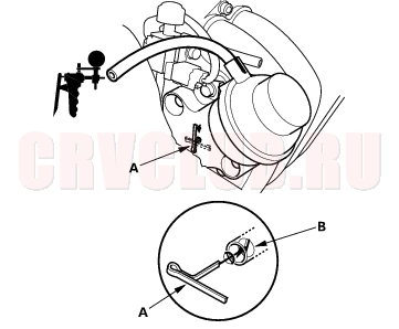
Does the IMRC actuator hold vacuum?
Yes : Go to step 24.
No : Replace the IMRC valve assembly.
Does the cotter pin move?
Yes : IMRC system is OK.
No : Replace the IMRC valve assembly.
Throttle Body Test11-180
With using a scan tool/Honda PGM Tester:
Do not adjust the throttle stop screw. It is preset at the factory. If the Malfunction Indicator Lamp (MIL) has been reported on, check for Diagnostic Trouble Codes (DLC) (see page 11-3) .
- With the engine off, check the throttle cable operation. The cable should operate without binding or sticking.
- If the cable operates OK, go to step 2.
- If the cable binds or sticks, check it and its routing. If the cable is faulty, reroute it or replace it, and adjust it (see page 11-183) , then go to step 2.
- Operate the throttle lever by hand to see if the throttle valve and/or shaft are too loose or too tight.
- If there is excessive play in the throttle valve shaft, or any binding in the throttle valve at the fully closed position or fully open, replace the throttle body.
- If the throttle valve and shaft are OK, go to step 3.
- Connect the scan tool/Honda PGM Tester to the Data Link Connector (DLC).
- Turn the ignition switch ON (II).
- Check the throttle position with the scan tool. The reading should be about 10% when the throttle is fully closed and about 90% when the throttle is fully opened.
- If the throttle position is correct, the throttle body is OK.
- If the throttle position is not correct, replace the throttle body.
Intake Air Bypass Control Thermal Valve Test11-181
- Start the engine. Then let it idle.
- NOTE: The engine coolant temperature must be below 65°C (149°F).
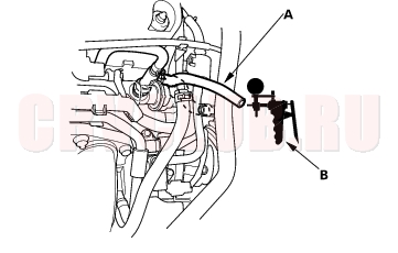
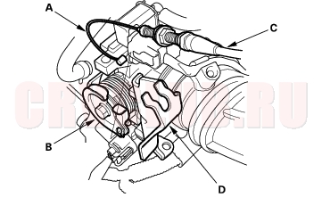
- Remove the vacuum hose (A) from the intake air duct, and connect a vacuum pump/gauge (B) to the hose.
- Raise and lower the engine speed, and make sure the vacuum gauge reading changes as the engine speed changes.
- If the vacuum reading does not change, check for these problems:
- Misrouted, leaking, broken, or clogged intake air bypass control system vacuum lines.
- A cracked or damage intake air bypass control thermal valve.
- Hold the engine at 3,000 rpm (min-1) with no load (in Park or neutral) until the radiator fan comes on, then let it idle.
- Raise and lower the engine speed, and make sure the vacuum gauge reading does not change as the rpm changes.
- If the vacuum reading changes, check for these problems:
- Misrouted, leaking, broken, or clogged intake air bypass control system vacuum lines.
- A cracked or damaged intake air bypass control thermal valve.
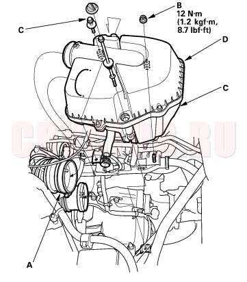
Air Cleaner Replacement11-182
- Remove the clamp (A), the nuts (B), and the bolts (C).
- Remove the air cleaner (D).
- Install the parts in the reverse order of removal.
Air Cleaner Element Replacement11-182
- Disconnect the PCV hose (A). Open the air cleaner housing cover (B).
- Remove the air cleaner (C) from the air clenaer housing (D).
- Install the parts in the reverse order of removal.
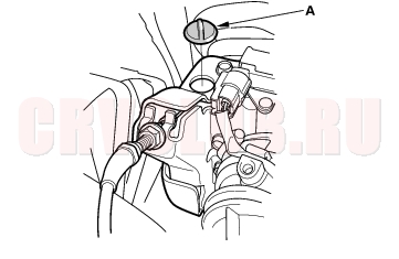
Throttle Cable Adjustment11-183
- Remove the throttle linkage cover grommet (A).
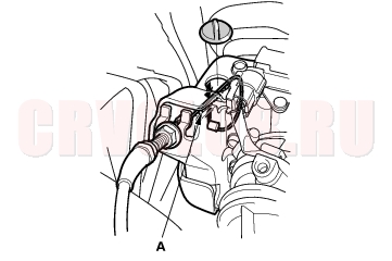
- Check cable free play at the throttle linkage. Cable deflection (A) should be 10 - 12 mm (3/8 - 1/2 in.).
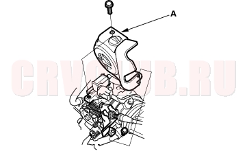
- If the deflection is not within spec (10 - 12 mm, 3/8 - 1/2 in.), remove the throttle linkage cover (A).
- Loosen the locknut (A), turn the adjusting nut (B) until the deflection (C) is as specified, then retighten the locknut.
- With the cable properly adjusted, check the throttle valve to be sure it opens fully when you push the accelerator pedal to the floor. Also check the throttle valve to be sure it returns to the idle position whenever you release the accelerator pedal.
Throttle Cable Removal/Installation11-184
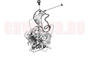
- Remove the throttle linkage cover (A).
- Fully open the throttle valve, then remove the throttle cable (A) from the throttle link (B).
- Remove the cable housing (C) from the cable bracket (D).
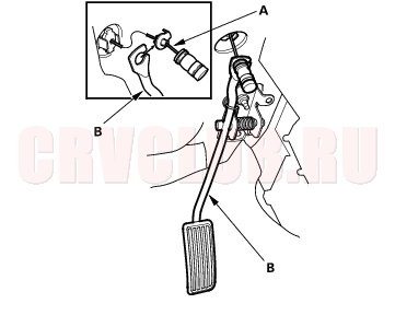
- Remove the throttle cable (A) from the accelerator pedal (B).
- Install in the reverse order of removal.
- After installing, start the engine. Hold the engine at 3,000 rpm (min-1) with no load (in Park or neutral) until the radiator fan comes on, then let it idle.
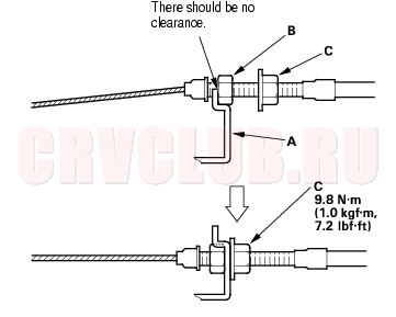
- Hold the cable, removing all slack from it.
- Set the locknut on the cable bracket (A).
Adjust the adjusting nut (B) so that its free play is
0 mm.
- Remove the cable from the throttle bracket (A). Reset the adjusting nut (B) and tighten the locknut (C).
- With the cable properly adjusted, check the throttle valve to be sure it opens fully when you push the accelerator pedal to the floor. Also check the throttle valve to be sure it returns to the idle position whenever you release the accelerator pedal.
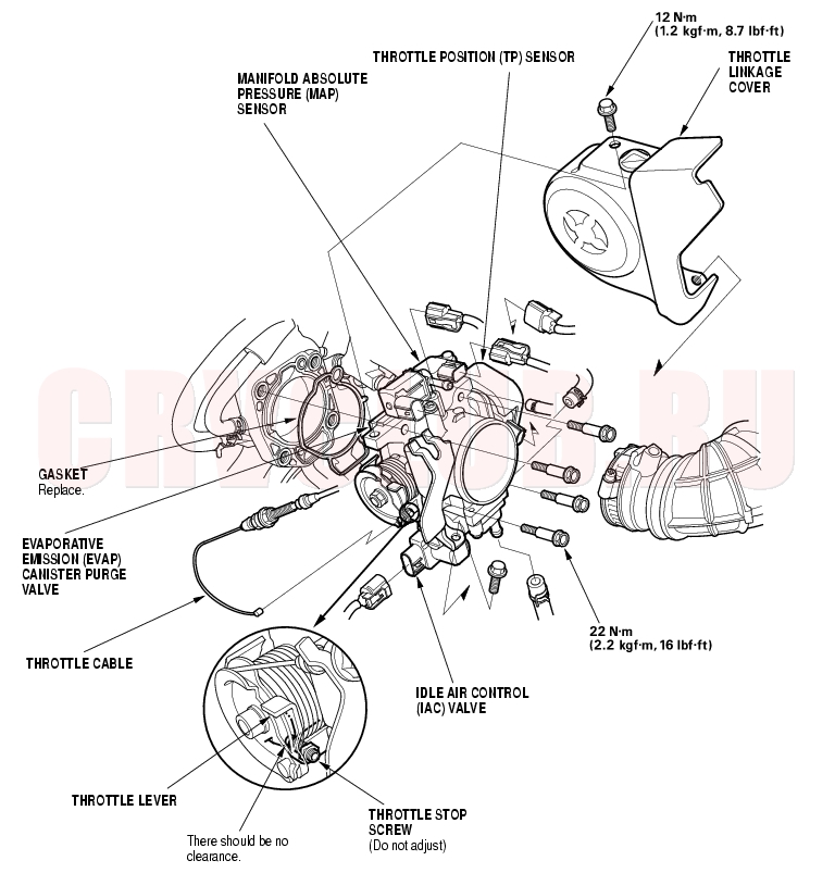
Throttle Body Removal/Installation11-185
Do not adjust the throttle stop screw. After reassembly, adjust the throttle cable (see page 11-183) . The Throttle Position (TP) sensor is not removable.
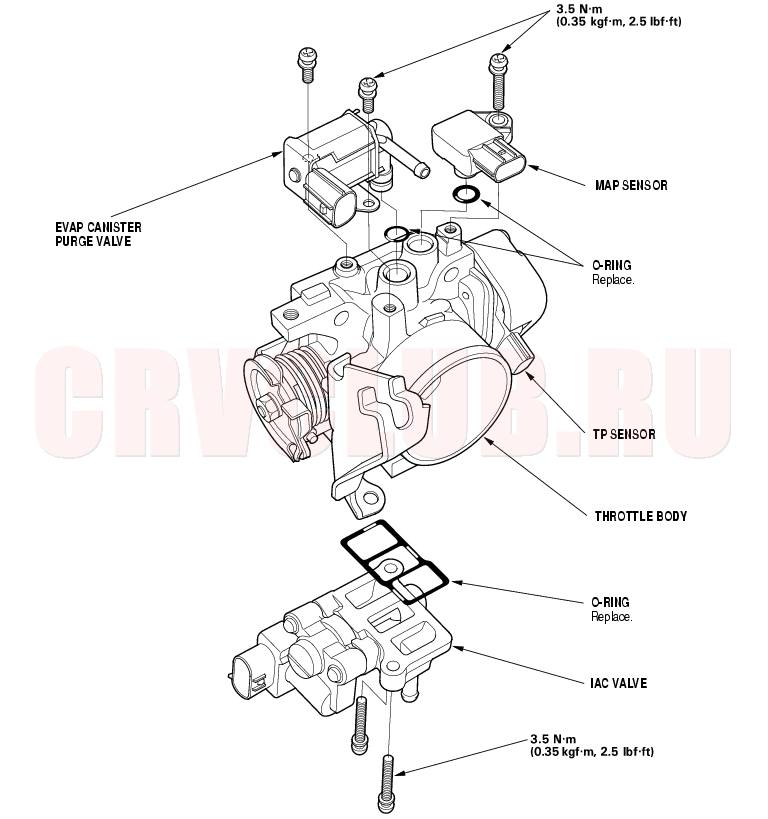
Throttle Body Disassembly/Reassembly11-186
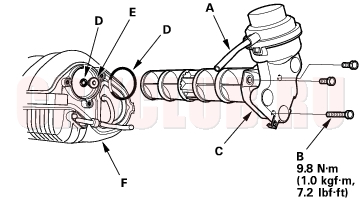
IMRC Valve Replacement11-187
- Remove the intake manifold (see page 09-2) .
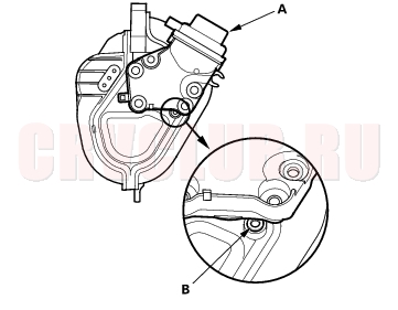
- Disconnect the vacuum hose (A).
- Remove the bolts (B).
- Remove the IMRC actuator assembly (C).
- NOTE:
- When installing the IMRC actuator, make sure the bearing (E) is firmly secure into place if necessary.
- Do not the IMRC assembly interfere with the intake manifold (F).
- When installing the IMRC actuator, replace the new O-rings (D).
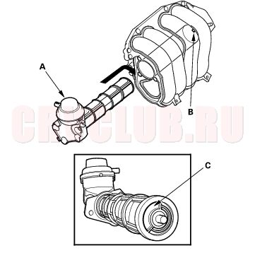
- Install the IMRC actuator assembly (A), then check the hole (B) appears.
- Turn the IMRC actuator assembly (A), and set the bolt holes.
NOTE: When turning the IMRC actuator assembly, make sure the stopper (B) and groove (C) are fit.
|
Fuel and Emissions11-1
Intake Air System11-176 |