Fuel Supply System11-149
|
Fuel and Emissions11-1
Fuel Supply System11-149 |
Fuel Supply System11-149
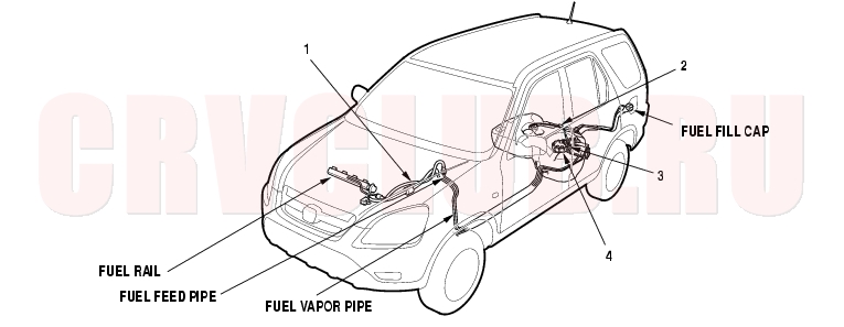
Component Location Index
KG, KS, KE, KR models:
Precautions, page 11-160 ; Removal, page 11-161 ; Installation, page 11-162 Replacement, page 11-169 Precautions, page 11-160 ; Removal, page 11-161 ; Installation, page 11-162 Troubleshooting, page 11-151 ; Replacement, page 11-167 Replacement, page 11-166 Test, page 11-173 Replacement, page 11-165
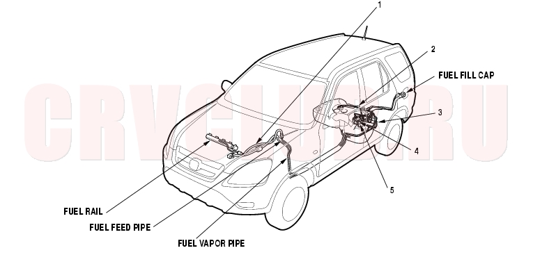
Except KG, KS, KE, KR, KZ models:
Precautions, page 11-160 ; Removal, page 11-161 ; Installation, page 11-162 Replacement, page 11-169 Replacement, page 11-166 Precautions, page 11-160 ; Removal, page 11-161 ; Installation, page 11-162 Troubleshooting, page 11-151 ; Replacement, page 11-167 Test, page 11-173 Replacement, page 11-165
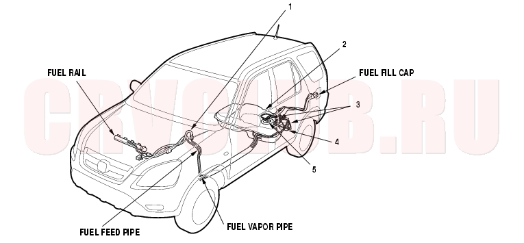
Component Location Index (cont'd)11-150
KZ model:
Precautions, page 11-160 ; Removal, page 11-161 ; Installation, page 11-162 Replacement, page 11-169 Precautions, page 11-160 ; Removal, page 11-161 ; Installation, page 11-162 Replacement, page 11-166 Troubleshooting, page 11-151 ; Replacement, page 11-167 Test, page 11-173 Replacement, page 11-165
*: The illustration shows LHD model.
Troubleshooting, page 11-102 Troubleshooting, page 11-151
Fuel Pump Circuit Troubleshooting11-151
If you suspect a problem with the fuel pump, check that the fuel pump actually runs; when it is on, you will hear some noise if you listen to the fuel fill port with the fuel fill cap removed. The fuel pump should run for 2 seconds when the ignition switch is first turned on. If the fuel pump does not make noise, check as follows:
NOTE: Information marked with an asterisk (*) applies to except KG, KS, KE, KR, KU, KN, KH, KY, KZ, FO, KQ, KK, KM models.
- Turn the ignition switch OFF.
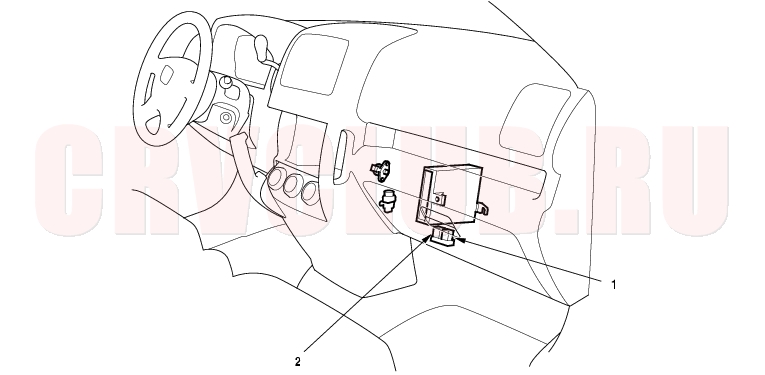
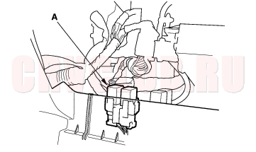
- Remove the glove box (see page 20-95) , PGM-FI main relay 2 (A).
*: The illustration shows LHD model.
- Turn the ignition switch ON (II).
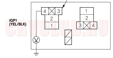
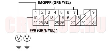
- Measure voltage between PGM-FI main relay 2 4P connector terminal No. 4 and body ground.
Is there battery voltage?
Yes : Go to step 5.
No : Repair open in the wire between the PGM-FI main relay 1 and the PGM-FI main relay 2.

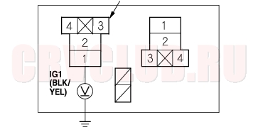
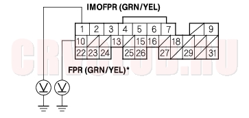
Is there battery voltage?
Yes : Go to step 6.
No : Repair open in the wire between the under-dash fuse/relay box and PGM-FI main relay 2.
- Turn the ignition switch OFF.
- Disconnect the negative cable from the battery.
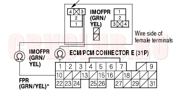
- Disconnect ECM/PCM connector E (31P).
- Check for continuity between PGM-FI main relay 2 4P connector terminal No. 3 and ECM/PCM connector terminal E1 (E10)*.
Is there continuity?
Yes : Go to step 10.
No : Repair open in the wire between the PGM-FI main relay 2 and the ECM/PCM (E1, E10*).
Fuel Pump Circuit Troubleshooting (cont'd)11-152
- Reinstall the PGM-FI main relay 2.
- Reconnect the negative cable to the battery.
- Turn the ignition switch ON (II).
- Measure voltage between ECM/PCM connector terminal E1 (E10)* and body ground.
Is there battery voltage?
Yes : Go to step 14.
No : Replace the PGM-FI main relay 2.
- Turn the ignition switch OFF.
- Disconnect the negative cable from the battery.
- Reconnect ECM/PCM connector E (31P).
- Reconnect the negative cable to the battery.
- Turn the ignition switch ON (II), and measure voltage between ECM/PCM connector terminal E1 (E10)* and body ground within the first 2 seconds after the ignition switch was turned ON (II).
Is there battery voltage?
Yes : Substitute a known-good ECM/PCM and recheck (see page 11-5). If symptom/indication goes away, replace the original ECM/PCM.
No : Go to step 19.
- Turn the ignition switch OFF.
- Fold the rear seats forward, and pull back the carpet to expose the access panel.
- Remove the access panel from the floor.
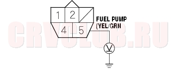
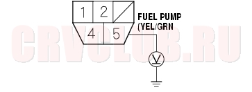
- Measure voltage between fuel pump 5P connector terminal No. 5 and body ground within the first 2 seconds after the ignition switch was turned ON (II).
Is there battery voltage?
Yes : Go to step 28.
No : Go to step 23.
11-153
- Turn the ignition switch ON (II).
- Measure voltage between fuel pump 5P connector terminal No. 5 and body ground within the first 2 seconds after the ignition switch was turned ON (II).
Is there battery voltage?
Yes : Replace the PGM-FI main relay 2.
No : Repair open in the wire between the PGM-FI main relay 2 and the fuel pump 5P connector.
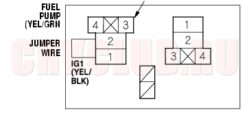
- Turn the ignition switch OFF.
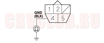
- Check for continuity between fuel pump 5P connector terminal No. 4 and body ground.
Is there continuity?
Yes : Replace the fuel pump.
No : Repair open in the wire between the fuel pump 5P connector and G551.
Fuel Pressure Relieving11-154
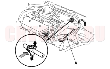
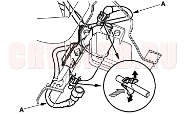
Before disconnecting fuel lines or hoses, release pressure from the system by loosening the fuel pulsation damper on top of the fuel rail.
- Make sure you have the anti-theft code for the radio,then write down the frequencies for the radio's preset buttons.
- Disconnect the negative cable from the battery.
- Remove the fuel fill cap and the engine cover.
- Use a wrench on the fuel pulsation damper (A).
- Place a rag or shop towel (B) over the fuel pulsation damper.
- Slowly loosen the fuel pulsation damper one complete turn.
- NOTE: Replace all washers whenever the fuel pulsation damper is loosened or removed.
Fuel Pressure Test11-154
Special Tools Required
Fuel pressure gauge 07406-0040002 Fuel pressure gauge attachment 07VAJ-0040100 Fuel pressure gauge set 07ZAJ-S5A0100
- Make sure you have the anti-theft code for the radio, then write down the frequencies for the radio's preset buttons.
- Disconnect the negative cable from the battery.
- Remove the fuel fill cap and the engine cover.
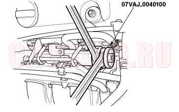
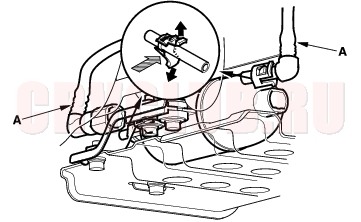
- Use a wrench on the fuel pulsation damper (A) at the fuel rail.
- Place a rag or shop towel (B) over the fuel pulsation damper.
- Slowly loosen the fuel pulsation damper one complete turn.
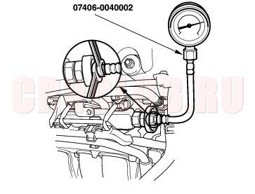
- Remove the fuel pulsation damper from its fitting, and attach the fuel pressure gauge attachment.
11-155
- Attach the fuel pressure gauge.
- Start the engine and let it idle.
- If the engine starts, go to step 11.
- If the engine does not start, go to step 10.
- Check to see if the fuel pump is running: listen to the fuel fill port with the fuel fill cap removed. The fuel pump should run for 2 seconds when the ignition switch is first turned ON (II).
- If the pump runs, go to step 11.
- If the pump does not run, perform the fuel pump circuit troubleshooting (see page 11-151)
- Read the pressure gauge. The pressure should be 330 - 380 kpa (3.4 - 3.9 kgf/cm2, 48 - 55 psi) (KZ model: 320 - 370 kpa (3.3 - 3.8 kgf/cm2, 47 - 54 psi)).
- If the pressure is OK, the test is complete.
- If the pressure is out of specification, replace the fuel pressure regulator (see page 11-165) and the fuel filter (see page 11-166) , then repeat the test.
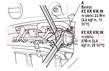
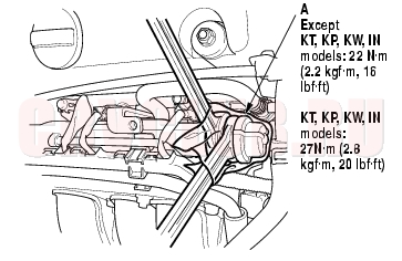
- Remove the pressure gauge, and reinstall the fuel pulsation damper with a new washer. Tighten the fuel pulsation damper to 22 N·m (2.2kgf·m, 16 lbf·ft) [KT, KP, KW, IN models: 27 N·m (2.8 kgf·m, 20 lbf·ft)].
NOTE: Disassemble and clean the fuel pressure gauge attachment thoroughly after use. Fuel Line Inspection11-156
Check the fuel system lines, hoses, and fuel filter for damage, leaks, and deterioration. Replace any damaged parts.
KG, KS, KE, KR models:
Except KG, KS, KE, KR, KZ models:
11-157
KZ model:
Fuel Line Inspection (cont'd)11-158
Check all clamps and retighten if necessary.
: Do not disconnect the hose from the pipe at these joints.
KG, KS, KE, KR models:
Except KG, KS, KE, KR, KZ models:
11-159
KZ model:
Fuel Tube/Quick-Connect Fittings Precaution11-160
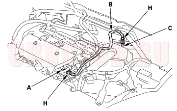
The fuel tube/quick-connect fittings connect the fuel rail (A) to fuel feed hose (B), the fuel feed hose (B) to the fuel line (C), and the fuel tube (D) to the fuel tank unit (E) and fuel tube (F) to the fuel filter (G). When removing or installing the fuel feed hose, fuel tank unit, or fuel tank, it is necessary to disconnect or connect the quick-connect fittings.
Pay attention to the following:
The fuel feed hose (B), fuel tube (D) and quick-connect fittings (H) are not heat-resistant; be careful not to damage them during welding or other heat-generating procedures. The fuel feed hose (B), fuel tube (D) and quick-connect fittings (H) are not acid-proof; do not touch them with a shop towel which was used for wiping battery electrolyte. Replace them if they came into contact with electrolyte or something similar. When connecting or disconnecting the fuel feed hose (B), fuel tube (D), and quick-connect fittings (H), be careful not to bend or twist them excessively. Replace them it damaged.
KG, KS, KE, KR models:
Except KG, KS, KE, KR, KZ models:
KZ model:
PH, FO, IN, MA models:
11-161
KZ model:
A disconnected quick-connect fitting can be reconnected, but the retainer on the mating pipe cannot be reused once it has been removed from the pipe. Replace the retainer when
replacing the fuel rail. replacing the fuel pipe. replacing the fuel pump. replacing the fuel filter. replacing the fuel gauge sending unit. it has been removed from the pipe. it is damaged.
Fuel Tube/Quick-Connect Fittings Removal11-161
- Relieve the fuel pressure (see page 11-154) .
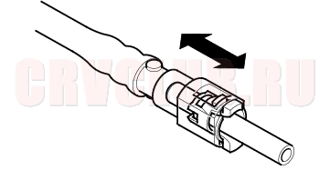
- Check the fuel quick-connect fitting for dirt, and clean if necessary.
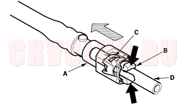
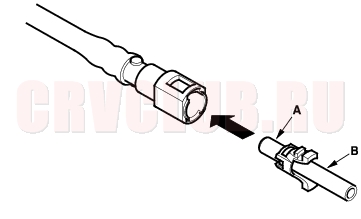
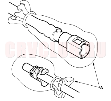
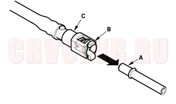
- Hold the connector (A) with one hand and squeeze the retainer tabs (B) with the other hand to release them from the locking pawls (C). Pull the connector off.
- NOTE:
- Be careful not to damage the pipe (D) or other parts. Do not use tools.
- If the connector does not move, keep the retainer tabs pressed down, and alternately pull and push the connector until it comes off easily.
- Do not remove the retainer from the pipe; once removed, the retainer must be replaced with a new one.
Fuel Tube/Quick-Connect Fittings Removal (cont'd)11-162
- Check the contact area (A) of the pipe (B) for dirt and damage.
- If the surface is dirty, clean it.
- If the surface is rusty or damaged, replace the fuel pump, fuel filter, or fuel feed pipe.
- To prevent damage and keep foreign matter out, cover the disconnected connector and pipe end with plastic bags (A).
NOTE: The retainer cannot be reused once it has been removed from the pipe.
Replace the retainer whenreplacing the fuel rail. replacing the fuel feed pipe. replacing the fuel pump. replacing the fuel filter. replacing the fuel gauge sending unit. it has been removed from the pipe. it is damaged.
Fuel Tube/Quick-Connect Fittings Installation11-162
- Check the contact area (A) of the pipe (B) for dirt and damage, and clean if necessary.
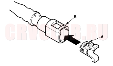
- Insert a new retainer (A) into the connector (B) if the retainer is damaged, or after
- replacing the fuel rail.
- replacing the fuel feed pipe.
- replacing the fuel pump.
- replacing the fuel filter.
- replacing the fuel gauge sending unit.
- removing the retainer from the pipe.
11-163
- Before connecting a new fuel tube/quick-connect fitting assembly (A), remove the old retainer (B) from the mating pipe.
KG, KS, KE, KR models:
Except KG, KS, KE, KR KZ models:
KZ model:
PH, FO, IN, MA models:
Fuel Tube/Quick-Connect Fittings Installation (cont'd)11-164
KZ model:
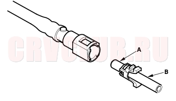
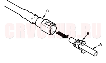
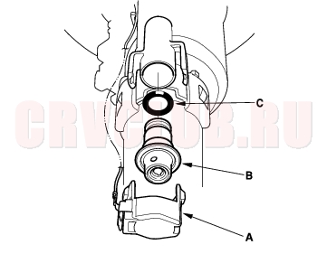
- Align the quick-connect fittings with the pipe (A), and align the retainer (B) locking pawls with the connector (C) grooves. Then press the quick-connect fittings onto the pipe until both retainer pawls lock with a clicking sound.
- NOTE: If it is hard to connect, put a small amount of new engine oil on the pipe end.
Connection with new retainer:
Reconnection to existing retainer:
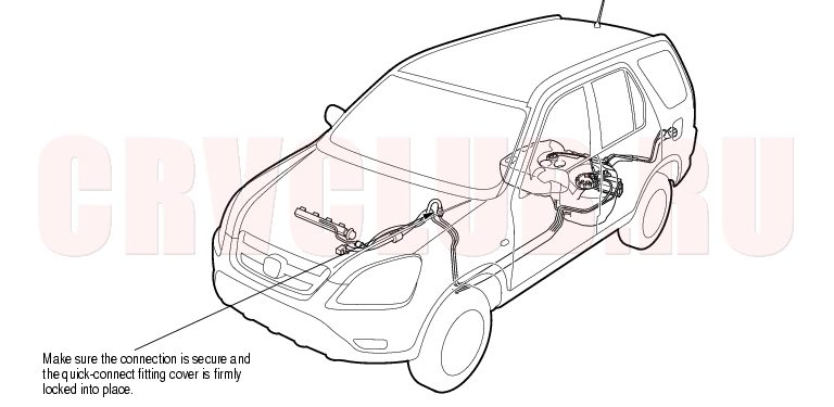
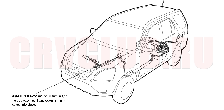
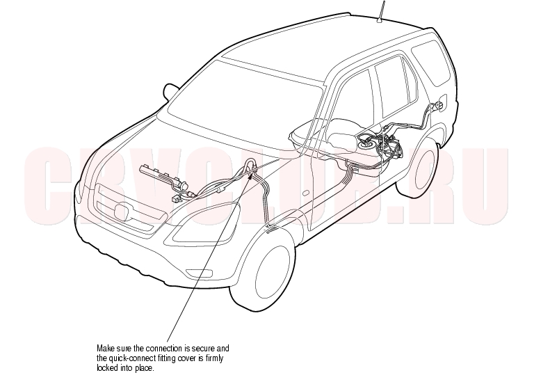
- Make sure the connection is secure and that the pawls are firmly locked into place; check visually and by pulling the connector.
- Reconnect the negative cable to the battery, and turn the ignition switch ON (II). The fuel pump will run for about 2 seconds, and fuel pressure will rise. Repeat two or three times, and check that there is no leakage in the fuel supply system.
Fuel Pressure Regulator Replacement11-165
Except KZ model:
- Remove the fuel pump (see page 11-167) .
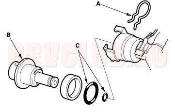
- Remove the clip (A).
- Remove the fuel pressure regulator (B).
- Install the part in the reverse order of removal with new O-rings (C).
KZ model:
- Remove the fuel pump (see page 11-167) .
- Remove the bracket (A).
- Remove the fuel pressure regulator (B).
- Install the part in the reverse order of removal with a new O-ring (C).
Fuel Filter Replacement11-166
The fuel filter should be replaced whenever the fuel pressure drops below the specified value (330 - 380 kPa (3.4 - 3.9 kgf/cm2, 48 - 55 psi), KZ model: 320 - 370 kPa, (3.3 - 3.8 kgf/cm2, 47 - 54 psi)) after making sure that the fuel pump and the fuel pressure regulator are OK.
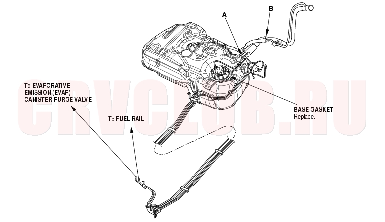
KG, KS, KE, KR models:
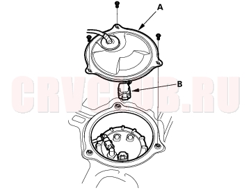
- Remove the fuel pump (see page 11-167) .
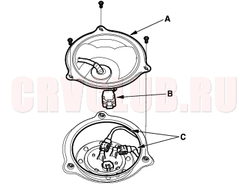
- Remove the fuel filter (A).
- Install the part in the reverse order of removal with a new base gasket (D) and new O-rings (E), then check these items:
- When connecting the wire harness, make sure the connection is secure and the terminal (B) is firmly locked into place.
- When installing the fuel gauge sending unit (C), make sure the connection is secure and the connector is firmly locked into place. Be careful not to bend or twist it excessively.
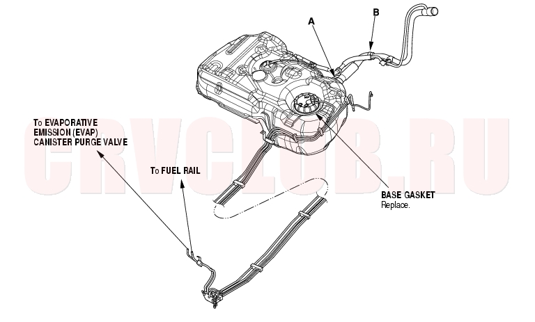
Except KG, KS, KE, KR models:
- Relieve fuel pressure (see page 11-154) .
- Disconnect the hose and quick-connect fittings (A) (see page 11-161) .
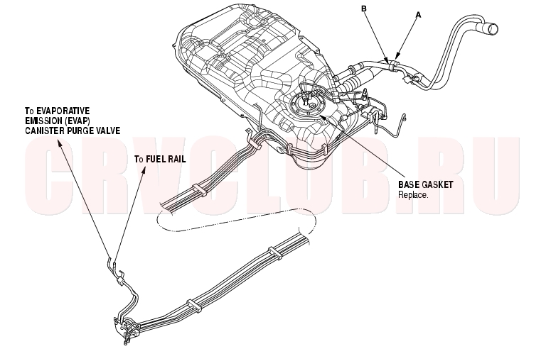
Except KZ model:
KZ model:
Fuel Pump/Fuel Gauge Sending Unit Replacement11-167
Special Tools Required
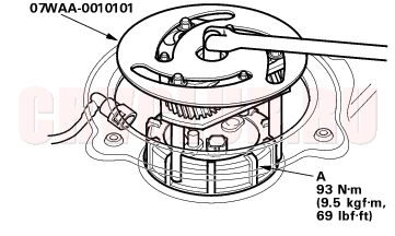
Adjustable ring wrench 07WAA-0010100
Except KZ model:
- Relieve the fuel pressure (see page 11-154) .
- Remove the fuel fill cap.
- Fold the rear seats forward, and pull back the carpet to expose the access panel.
- Remove the access panel (A) from the floor.
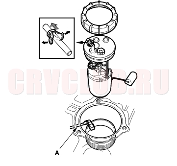
*: The illustration shows KG, KS, KE, KR models.
- Disconnect the fuel pump 5P connector (B).
- Disconnect the quick-connect fitting (C) from the fuel tank unit.
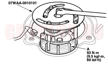
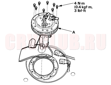
- Using the tool, loosen the fuel tank unit locknut (A).
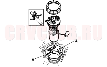
*: The illustration shows KG, KS, KE, KR models.
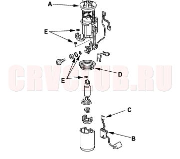
- Remove the locknut (A) and the fuel pump assembly.
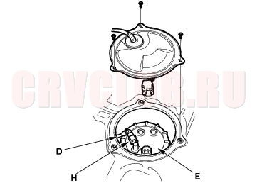
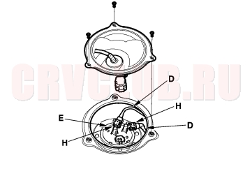
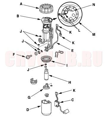
- Remove the strainer case (B), the fuel gauge sending unit (C), the case (D), the wire harness (E), and the fuel pressure regulator (F).
- When connecting the fuel pump assembly, make sure the connection is secure and the suction filter (G) is firmly connected to the fuel pump (H).
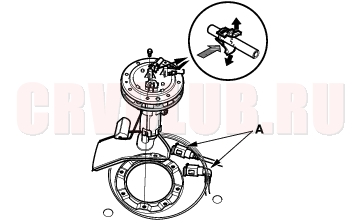
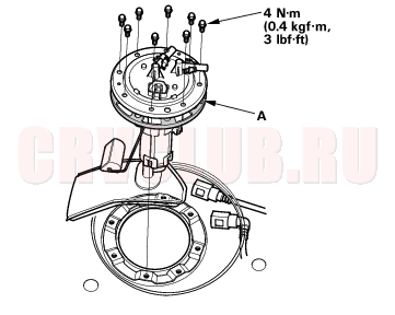
- Install the fuel pump assembly in the reverse order of removal with a new base gasket (I) and new O-rings (J), then check these items:
- When connecting the wire harness, make sure the connection is secure and the connector (K) is firmly locked into the place.
- When installing the fuel gauge sending unit, make sure the connection is secure and the connector is firmly locked into place. Be careful not to bend or twist it excessively.
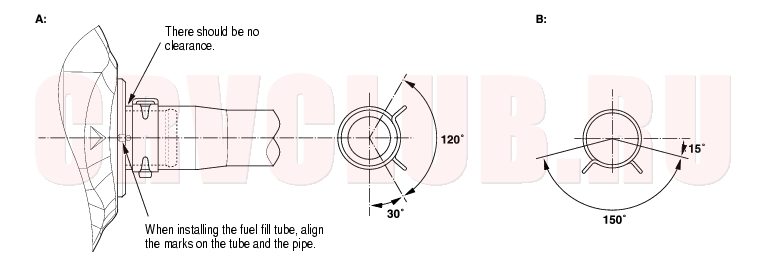
- When installing the fuel pump assembly align, the marks (L) on the fuel tank (M) and the fuel pump assembly (N).
Fuel Pump/Fuel Gauge Sending Unit Replacement (cont'd)11-168
KZ model:
- Relieve the fuel pressure (see page 11-154) .
- Remove the fuel fill cap.
- Fold the rear seats forward, and pull back the carpet to expose the access panel.
- Remove the access panel (A) from the floor.
- Disconnect the fuel pump 5P connector (B).
- Disconnect the quick-connect fittings (C) from the fuel tank unit.
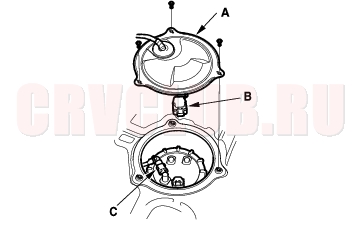
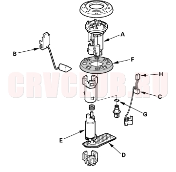
- Remove the fuel tank unit (A).
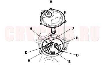
- Remove the strainer case (A), the fuel gauge sending unit (B), the wire harness (C).
- When connecting the fuel tank unit, make sure the connection is secure and the suction filter (D) is firmly connected to the fuel pump (E).
- Install the part in the reverse order of removal with a new base gasket (F) and new O-rings (G), then check these items:
- When connecting the wire harness, make sure the connection is secure and the connector (H) is firmly locked into the place.
- When installing the fuel gauge sending unit, make sure the connection is secure and the connector is firmly locked into place. Be careful not to bend or twist it excessively.
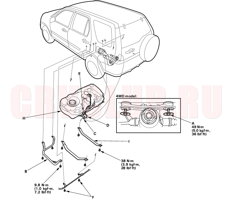
Fuel Tank Replacement11-169
Except KZ model:
- Drain the fuel tank: Remove the fuel pump assembly (see page 11-167) . Using a hand pump, hose and container suitable for gasoline, draw the fuel from the fuel tank.
- Jack up the vehicle, and support it with jackstands.
- 4WD model:
Remove the propeller shaft (see page 16-33) . Remove the rear differential mounting bolt (A), then support it with jackstands.
KG, KS, KE, KR models:
Fuel Tank Replacement (cont'd)11-170
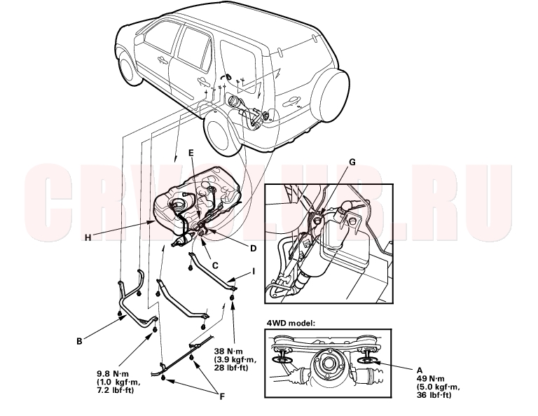
Except KG, KS, KE, KR models:
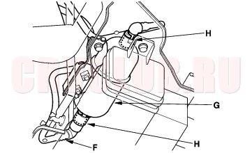
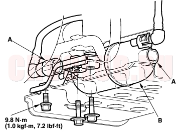
- Loosen the Evaporative Emission (EVAP) canister bracket bolt.
- Remove the fuel tank guard (B).
- Loosen the clamp (C).
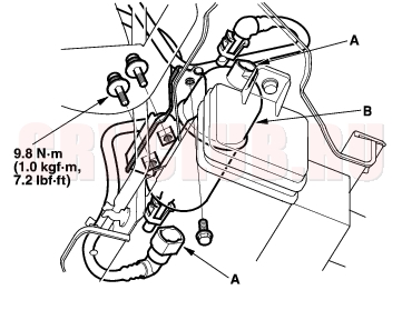
- Disconnect the fuel vapor hose (D), hoses (E) and wire stay bolts (F). Slide back the clamps, then twist the hoses as you pull to avoid damaging them.
- Except KG, KS, KE, KR models:
Remove the fuel filter bracket bolt (G).
- Place a jack, or other support, under the fuel tank (H).
- Remove the strap bolts, and the strap (I).
- Remove the fuel tank.
- Install the remaining parts in the reverse order of removal.
11-171
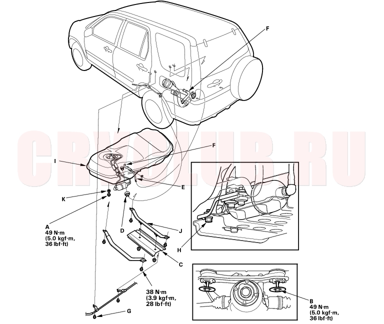
KZ model:
- Relieve the fuel pressure (see page 11-154) .
- Fold the rear seats forward, and pull back the carpet to expose the access panel.
- Remove the access panel, disconnect the quick connect fittings from the fuel pump.
- Jack up the vehicle, and support it with jackstands.
- Remove the drain bolt (A), and drain the fuel into an approved container.
- Remove the propeller shaft (see page 16-33) . Remove the rear differential mounting bolt (B), then support it with jackstands.
Fuel Tank Replacement (cont'd)11-172
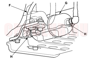
- Loosen the Evaporative Emission (EVAP) canister bracket bolt.
- Remove the fuel tank guard (C).
- Loosen the clamp (D).
- Disconnect the fuel vapor hose (E) and hoses (F) and wire stay bolts (G). Slide back the clamps, then twist the hoses as you pull to avoid damaging them.
- Remove the fuel filter bracket (H).
- Place a jack, or other support, under the fuel tank (I).
- Remove the strap bolts, and the strap (J).
- Remove the fuel tank.
- Install the drain bolt with a new washer (K), then coat the drain bolt with Noxrust 124B or equivalent. Allow the Noxrust or equivalent to dry for 20 minutes.
- Install the remaining parts in the reverse order of removal.
Fuel Gauge Sending Unit Test11-173
Special Tools Required
Adjustable ring wrench 07WAA-0010100
NOTE: For the fuel gauge system circuit diagram, refer to the Gauges Circuit Diagram (see page 22A-68) .
- Check the No. 10 METER (7.5A) fuse in the under-dash fuse/relay box before testing.
- Do the gauge drive circuit check (see page 22A-67) .
- If the fuel gauge needle sweeps from the minimum to maximum position and then returns to the minimum position, the gauge is OK. Go to step 3.
- If the fuel gauge needle does not sweep correctly, replace the gauge assembly and retest.
- Turn the ignition switch OFF.
- Remove the rear seat cushion (see page 20-114) .
- Remove the access panel (A) from the floor.
*: The illustration shows KG, KS, KE, KR, KZ models.
- Disconnect the fuel pump 5P connector (B).
- Measure voltage between the fuel pump 5P connector terminals No. 1 and No. 2 with the ignition switch ON (II). There should be battery voltage.
- If the voltage is OK, go to step 8.
- If the voltage is not as specified, check for:
- a short YEL/BLK to ground.
- an open in the YEL/BLK or BLK wire.
- poor ground (G551).
- Turn the ignition switch OFF. Remove the No. 9 BACK UP (10A) fuse from the under-hood fuse/relay box for at least 30 seconds, then reinstall it.
- Install a 12
resistor between the fuel pump 5P connector terminals No. 1 and No. 2, then turn the ignition switch ON (II).
Fuel Gauge Sending Unit Test (cont'd)11-174
- Check that the pointer of the fuel gauge indicates ''F''.
- If the pointer of the fuel gauge does not indicate ''F'', replace the gauge.
- If the gauge is OK, inspect the fuel gauge sending unit.
- NOTE: The pointer of the fuel gauge returns to the bottom of the gauge dial when the ignition switch is OFF, regardless of the fuel level.
- Relieve the fuel pressure (see page 11-154) .
- Remove the fuel fill cap.
- Disconnect the quick-connect fittings from the fuel pump.
- Except KZ model:
Using the tool, loosen the locknut (A), and remove the fuel pump assembly from the fuel tank.
*: The illustration shows KG, KS, KE, KR model.
- KZ model:
Remove the fuel pump assembly.
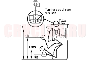
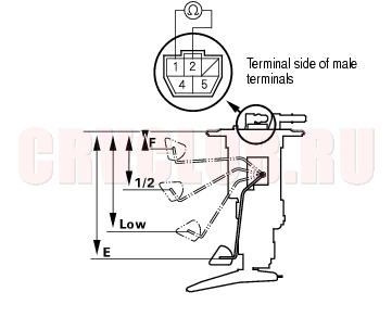
- Measure the resistance between the No. 1 and No. 2 terminals with the float at E (EMPTY), 1/2 (HALF FULL), and F (FULL) positions.
If you do not get the following readings, replace the fuel gauge sending unit (see page 11-167) .
Except KZ model:
Resistance ( 11 -13 67.6 -73.6 113.5 -121.2 130 -132
KZ model:
Resistance ( 11 -13 67.6 -73.6 110.8 -116.8 130 -132
NOTE: Remove the No. 9 BACK UP (10A) fuse from the under-hood fuse/relay box for at least 10 seconds after completing troubleshooting otherwise it may take up to 20 minutes for the fuel gauge to indicate the correct fuel level. Except KZ model:
KZ model:
Low Fuel Indicator Light Test11-175
- Do the fuel gauge sending unit test (see page 11-173) .
- If the system is OK, go to step 2.
- If the system has any malfunction, repair it.
- Turn the ignition switch OFF. Remove the No. 9 BACK UP (10A) fuse from the under-hood fuse/relay box for at least 30 seconds, then reinstall it.
- Turn the ignition switch ON (II) with the float at the E (EMPTY) position.
- If the low fuel indicator light is on, go to step 3.
- If the low fuel indicator light is not on, refer to the low fuel indicator Circuit Diagram (see page 22A-69) and check the circuit.
- Turn the ignition switch OFF. Remove the No. 9 BACK UP (10A) fuse from the under-hood fuse/relay box for at least 30 seconds, then reinstall it.
- Lift the float above the 1/2 position.
- If the low fuel indicator light goes off, the system is OK.
- If the low fuel indicator light is still on, refer to the low fuel indicator Circuit Diagram (see page 22A-69) and check the circuit.
|
Fuel and Emissions11-1
Fuel Supply System11-149 |