Exterior Lights 22A-79
|
Body Electrical22A-1
Exterior Lights 22A-79 |
Exterior Lights 22A-79
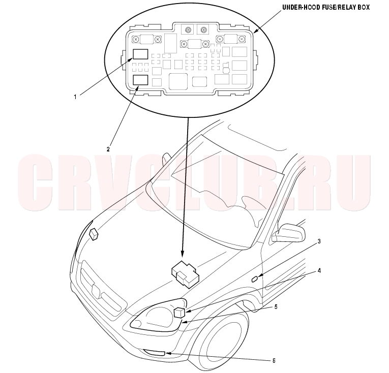
Component Location Index
NOTE: LHD type is shown, RHD type is similar.
Test, page 22A-62 Test, page 22A-62 Replacement, page 22A-109 Troubleshooting, page 22A-100 Replacement, page 22A-102 ; Adjustment, page 22A-103 ; Damaged Headlight Alignment Pin Procedure, page 22A-104 Replacement, page 22A-108 ; Adjustment, page 22A-109
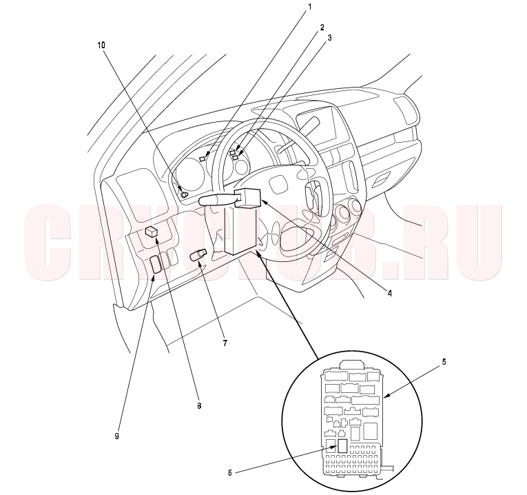
Component Location Index (cont'd) 22A-80
NOTE: LHD type is shown, RHD type is similar.
Bulb Replacement, page 22A-75 Bulb Replacement, page 22A-75 Test, page 22A-98 ; Replacement, page 22A-98 Test, page 22A-98 Test, page 22A-98 Test, page 22A-62 Test, page 22A-108 Test, page 22A-62 Test, page 22A-101
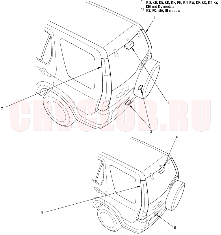
22A-81
Replacement, page 22A-105
Replacement, page 22A-105 Replacement, page 22A-105
Replacement, page 22A-105 Replacement, page 22A-105
Replacement, page 22A-105 Replacement, page 22A-105
Replacement, page 22A-105 Replacement, page 22A-106
Replacement, page 22A-105 Replacement, page 22A-107
Replacement, page 22A-105 Replacement, page 22A-106
Replacement, page 22A-105 Replacement, page 22A-107
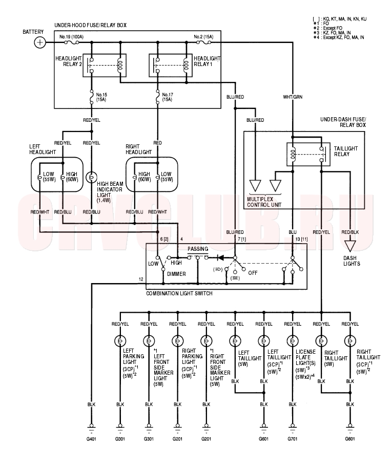
Circuit Diagram - With Daytime Running Lights 22A-82
22A-83
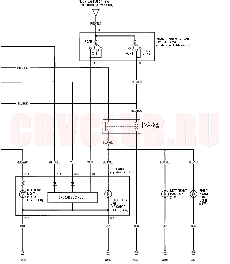
Circuit Diagram - Front/Rear Fog Lights 22A-84
22A-85
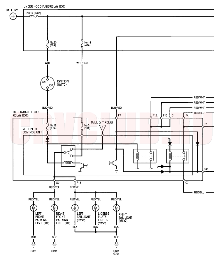
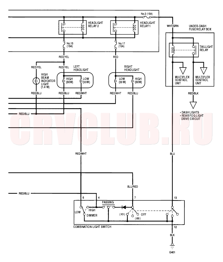
Circuit Diagram 22A-86
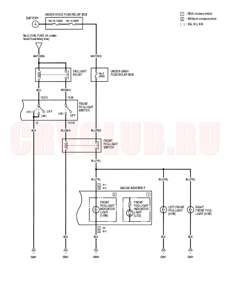
Circuit Diagram - Front Fog Lights 22A-87
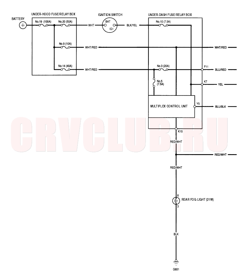
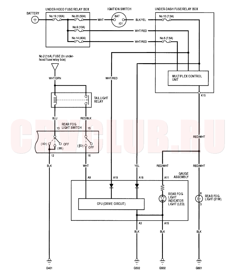
Circuit Diagram - Rear Fog Light 22A-88
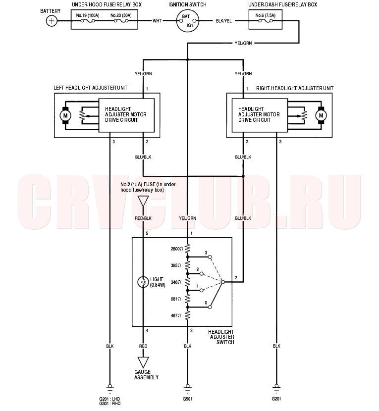
Circuit Diagram - Headlights Adjuster 22A-89
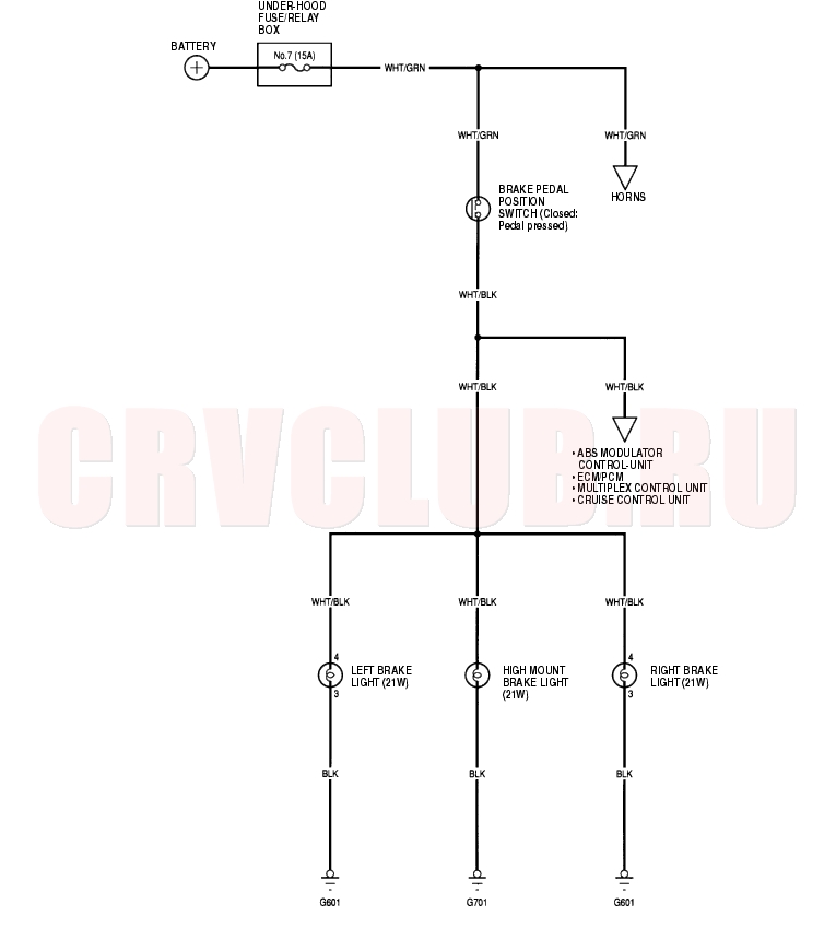
Circuit Diagram - Brake Lights 22A-90
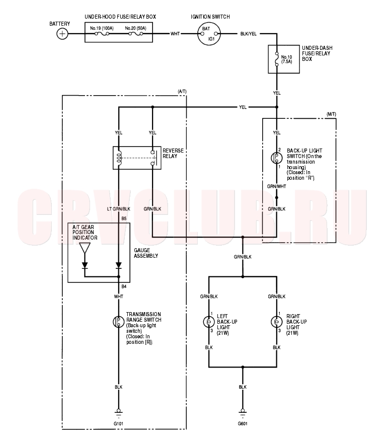
Circuit Diagram - Back-up Lights 22A-91
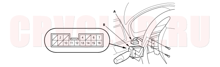
Combination Light Switch Test/Replacement 22A-92
- Remove the steering column covers (see page 17-24) .
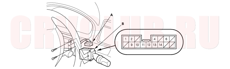
- Disconnect the 16P connector (A) from the combination light switch (B).
22A-93
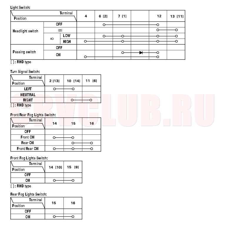
- Inspect the connector terminals to be sure they are all making good contact.
- If the terminals are bent, loose or corroded, repair them as necessary, and recheck the system.
- If the terminals look OK, check for continuity between the terminals in each switch position according to the tables.
- If the continuity is not specified, replace the switch.
Headlight Adjuster Unit Troubleshooting 22A-94
NOTE: Before testing, check for a blown No. 6 (7.5A) fuse in the under-dash fuse/relay box.
Is there continuity?
Yes : Go to step 3.
No : Check for these problems:

Repair open in the BLK wire between the headlight adjuster unit and body ground. Poor ground (G201, G301). Is there battery voltage?
Yes : Go to step 4.
No : Repair open in the YEL/GRN wire between the headlight adjuster unit and under-dash fuse/relay box.
- Using an ohmmeter, measure resistance between the No. 2 terminal and body ground in position 0 of the headlight adjuster switch.
Is there about 730
?
Yes : Check for frozen, stuck or improperly installed the headlight adjuster unit. If the mechanical check is OK, replace the headlight adjuster unit.
No : Check for these problems:
An open in the BLU/BLK wire between the headlight adjuster unit and headlight adjuster switch. A faulty headlight adjuster switch. Headlight Adjuster Switch Test 22A-95
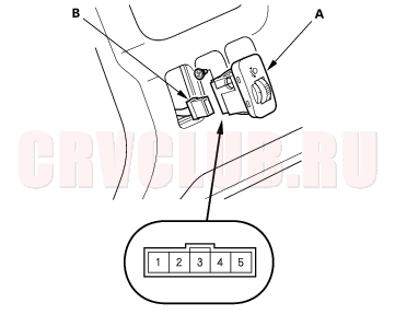
- Remove the dashboard lower cover (see page 20-88) .
- Carefully push out the headlight adjuster switch (A) from behind the dashboard.
- Disconnect the 5P connector (B) from the switch.
- Measure resistance between the No. 1 and No. 3 terminals and No. 1 and No. 2 terminals at positions 0, 1, 2, and 3 by moving the switch knob.
Between the No. 1 and No. 3 terminals:
About 4.7 k
Between the No. 1 and No. 2 terminals:
Knob position 0 1 2 3 Resistance
[About (k4.2 3.6 3.2 2.8
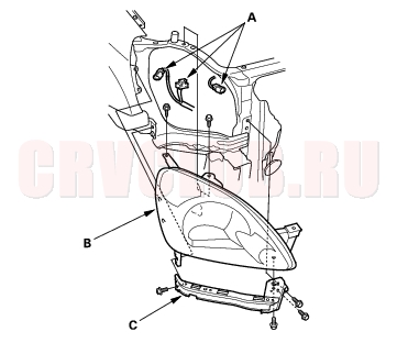
Headlight Replacement 22A-96
- Remove the front bumper (see page 20-130) .
- Disconnect the connectors (A) from the headlight (B).
Headlight: 60/55 W
Front Parking Light: 5 W or 3 CP
Front Turn Signal Light: 21 W
Front Turn Signal/Side Maker Light: 21 /5 W
- Remove the screw and mounting bolts, then remove the corner upper beam (C) and headlight assembly.
- Install in the reverse order of removal.
- After replacement, adjust the headlights to local requirements.
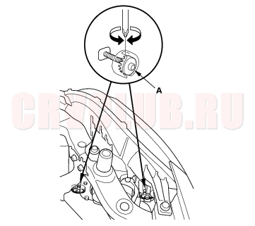
Headlight Adjustment 22A-96
Headlights become very hot during use; do not touch them or any attaching hardware immediately after they have been turned off.
Before adjusting the headlights:
Park the vehicle on a level surface. Make sure the tire pressures are correct. The driver or someone who weights the same should sit in the driver's seat. Adjust the headlights to local requirements by turning the adjusters (A).
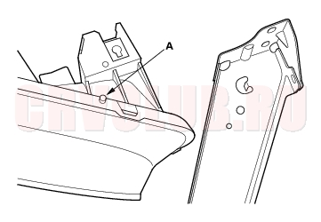
Damaged Headlight Alignment Pin Procedure 22A-97
If the alignment pin (A) was broken in a collision and the headlight assembly itself was not damaged, the headlight assembly can be reused.
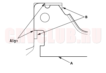
- Align the corner upper beam (A) with the guides (B) on the headlight housing.
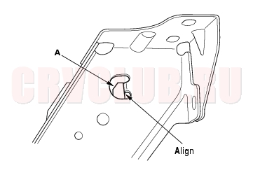
- Align the headlight housing with the flange (A) before tightening the bolts.
- Reinstall the headlight assembly, and adjust the headlights to local requirements (see page 22A-92) .
Taillight Replacement 22A-98
- Open the tailgate.
- Remove the rear side trim panel (see page 20-77) .
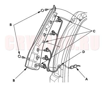
- Disconnect the 6P connector (A) from the taillight.
- Remove the mounting bolt covers from the taillight.
- Remove the mounting bolts from the taillight.
Brake/Taillight: 21/5 W
Back-up Light: 21 W
Rear Turn Signal Light: 21 W
Taillight: 5 W or 3 CP
Rear Fog Light: 21 W
- Pull the taillight away from the body to disengage the three clips (C).
- Remove the taillight harness grommet (D) from the body.
- Pull the harness and the 6P connector out of the body, and disconnect the connector. Remove the taillight.
- Turn the bulb socket 45° counterclockwise to remove the bulb socket.
- Install the taillight in the reverse order of removal and run water over it to make sure it does not leak.
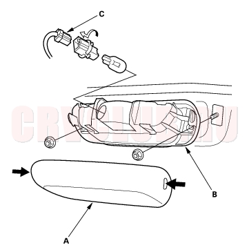
High Mount Brake Light Replacement 22A-98
High Mount Brake Light Bulb: 21 W
- Disconnect the 2P connector (C).
- Remove the mounting nuts and the housing.
- Install the high mount broke light in the reverse order of removal.
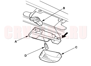
License Plate Light Replacement 22A-99
License Plate Light Bulb: 5 W
- Disconnect the 2P connector (B) from the light.
- Take the lens (C) off, then remove the bulb (D).
- Install the light in the reverse order of removal.
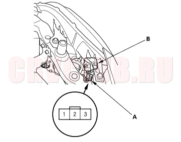
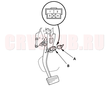
Brake Pedal Position Switch Test 22A-99
- Remove the driver's dashboard lower cover (see page 20-88) .
- Disconnect the 4P connector (A) from the brake pedal position switch (B).
- Check for continuity between the No. 1 and No. 2 terminals.
- There should be continuity when the brake pedal is pressed.
- There should be no continuity when the brake pedal is released.
- Check for continuity between the No. 3 and No. 4 terminals (with cruise control).
- There should be no continuity when the brake pedal is pressed.
- There should be continuity when the brake pedal is released.
- If necessary, adjust or replace the switch, or adjust the pedal height (see page 19A-5) .
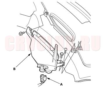
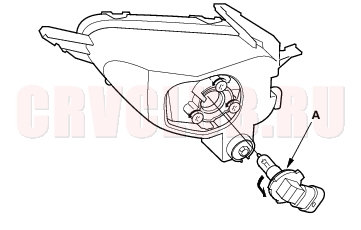
Front Fog Lights Replacement 22A-100
- Remove the front bumper (see page 20-130) .
- Disconnect the 2P connector (A) from the front fog light.
- Remove the screw and mounting bolts from the front fog light (B).
- Turn the bulb socket (A) 45° counterclockwise to remove the bulb.
Front Fog Light: 51 W
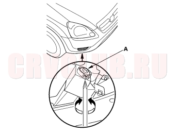
Front Fog Lights Adjustment 22A-100
Before adjusting the fog lights:
Park the vehicle on a level surface. Make sure the tire pressures are correct. The driver or someone who weights the same should sit in the driver's seat. Adjust the fog lights to local requirements by turning the adjuster (A).
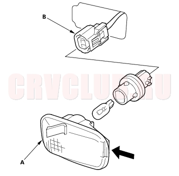
Side Turn Signal Lights Replacement 22A-101
NOTE: Be careful not to damage the fender.
Side Turn Signal Light: 5W
|
Body Electrical22A-1
Exterior Lights 22A-79 |