Gauges 22A-64
|
Body Electrical22A-1
Gauges 22A-64 |
Gauges 22A-64
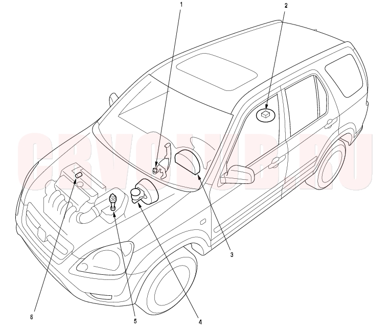
Component Location Index
NOTE: LHD type is shown, RHD type is similar.
page 19A-11 page 11-173 Self-diagnosis Procedure, page 22A-69 ; Outside, Air Temperature Indicator Test, page 22A-83 ; Gauge Bulb Replacement, page 22A-75 ; Replacement, page 22A-77 ; Coolant Temperature Gauge Troubleshooting, page 22A-77 page 19A-11 Troubleshooting, page 22A-78 ; Replacement, page 22A-82 page 08-4
22A-65
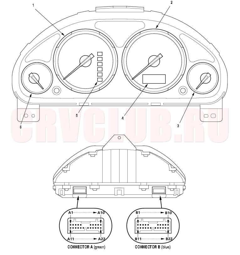
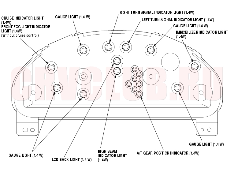
Gauge/Terminal Location Index
Vehicle Speed Signal Circuit Troubleshooting, page 22A-78 Troubleshooting, page 11-173 Troubleshooting, page 22A-77
Self-diagnostic Procedure 22A-66
The gauge assembly has a self-diagnosis function that checks these circuits:
The beeper drive circuit The indicator drive circuit The LCD segments The gauges drive circuit (Speedometer, Tachometer, Fuel gauge, Coolant temperature gauge) The communication line (the coolant temperature signal line between the gauge and the ECM/PCM) Entering the self-diagnosis function:
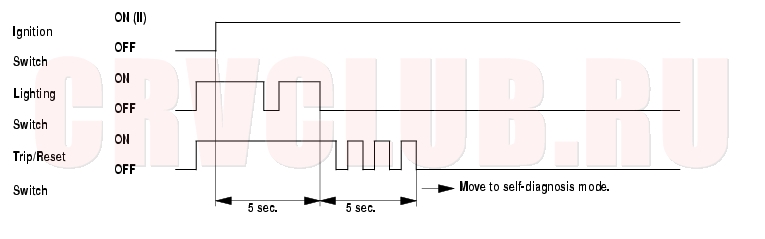
Before entering the self-diagnosis function, check the No. 9 (10A) fuse in the under-hood fuse/relay box and No. 10 (7.5A) fuse in the under-dash fuse/relay box.
- Push and hold the trip/reset button.
- Turn the headlights ON.
- Turn the ignition switch ON (II).
- With in 5 sec., turn the headlights OFF, then ON and OFF again.
- With in 5 sec., release the trip/reset button, then push and release the button four times.
While in the self-diagnosis mode, the dash lights brightness controller operates normally. While in the self-diagnosis mode, the trip/reset button is used to start the Beeper Drive Circuit Test and the Gauge Drive Circuit Check. If the vehicle speed exceeds 1.2 mph (2 km/h) or the ignition switch is turned OFF, the self-diagnosis mode ends.
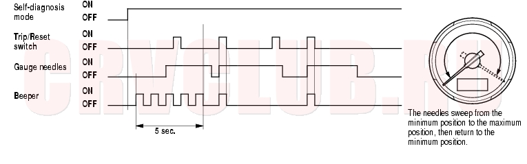
The Beeper Drive Circuit Check:
When entering the self-diagnosis mode, the beeper sounds five times.
The Indicator Drive Circuit Check:
When entering the self-diagnosis mode, these indicator lights blink:
Seat belt indicator light, Door indicator light, Brake system light, Charging system light, Low fuel indicator light, Tailgace indicator light.
A/T gear position Indicator (except [P], [R], [N])22A-67
The LCD Segments Check:
When entering the self-diagnosis mode, the odo/trip segments blinks five times.
The Gauge Drive Circuit Check:
When entering the self-diagnosis mode, the speedometer, the tachometer, the fuel gauge, and the coolant temperature gauge needles move from the minimum position to the maximum position, then return to the minimum position.
Note:
After the beeper stops sounding and the gauge needles return to the minimum position, pushing the trip/reset button starts the Beeper Drive Circuit Check (one beep), and the Gauge Drive Circuit Check again.
The check cannot be started until the gauge needles return the minimum position.
The Communication Line Check:
In the self-diagnosis mode, and after the odo/trip LCD Segments Check, the self-diagnosis starts the Communication Line Check.
If all segments comes on, the communication line is OK.
If the word "Error" is indicated, there is a malfunction in the communication line between the gauge assembly, the multiplex control unit, and the ECM/PCM. Go to Multiplex System Troubleshooting (see page 22A-261) .
Ending the self-diagnosis function:
Turn the ignition switch OFF.
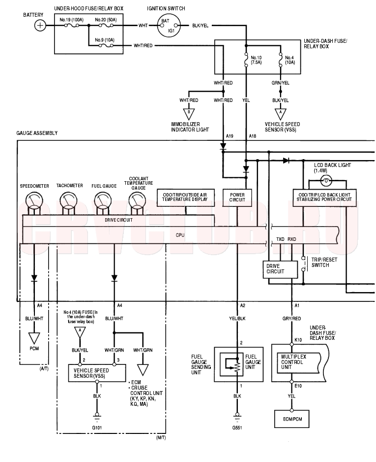
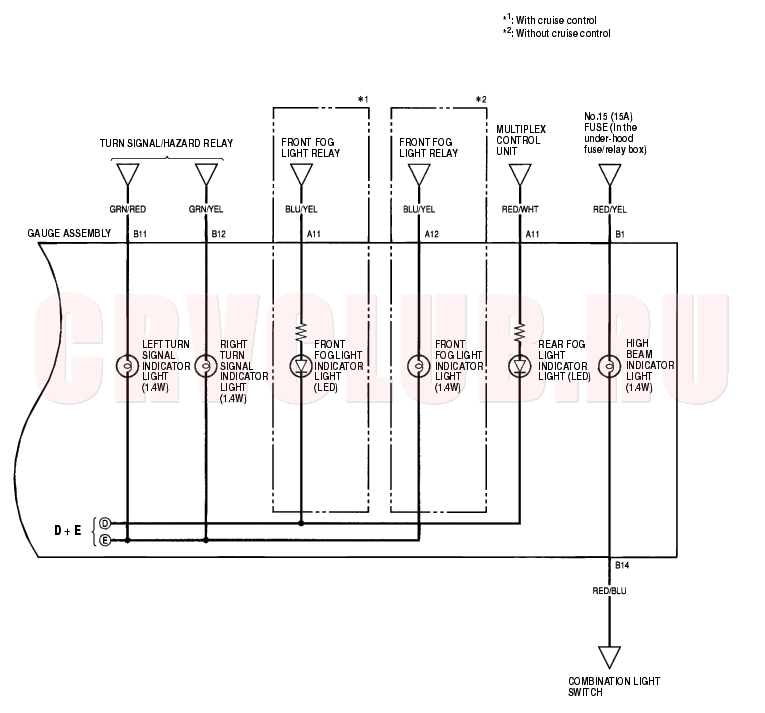
Note: If the vehicle speed exceeds 1.2 mph (2 km/h), the self-diagnosis function ends.Circuit Diagram 22A-68
Circuit Diagram (cont'd) 22A-69
To page 22A-73 To page 22A-73
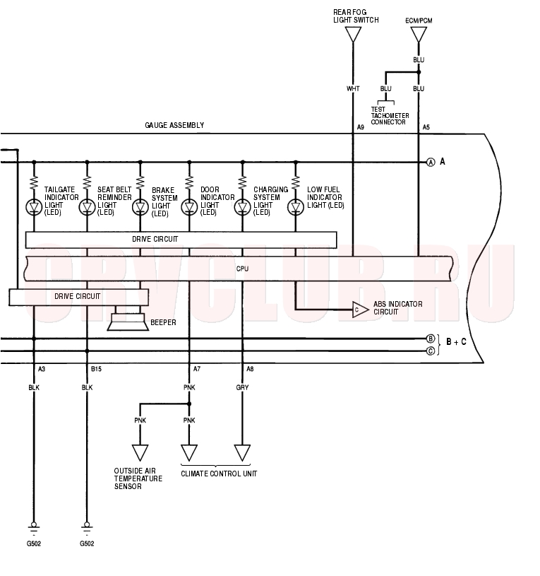
Circuit Diagram (cont'd) 22A-70
From page 22A-72 From page 22A-72
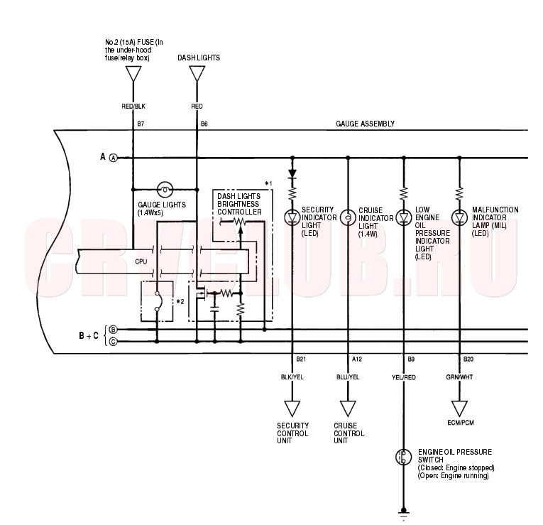
Circuit Diagram (cont'd) 22A-71
To page 22A-75
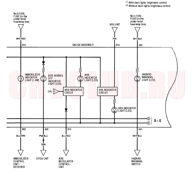
Circuit Diagram (cont'd) 22A-72
From page 22A-74
Gauge Bulb Replacement 22A-73
Gauge Assembly Replacement 22A-74
- Remove the driver's dashboard lower cover (see page 20-88) , then remove the instrument panel (see page 20-87) .
- Place a clean shop towel under the gauge assembly to prevent scratching the steering column or dashboard.
- Remove the three mounting screws from the gauge assembly (A).
- Disconnect the connectors (B), and remove the gauge assembly.
- Install the gauge assembly in the reverse order of removal.
Coolant Temperature Gauge Troubleshooting 22A-74
Before testing, check the No. 9 (10A) fuse in the under-hood fuse/relay box and the No. 10 (7.5A) fuse in the under-dash fuse/relay box.
Does the MIL come on and stay on?
Yes : Troubleshoot the cause of the ECM/PCM DTC (see page 11-62), and recheck.
No : Go to step 2.
- Check for a multiplex control unit DTC (see page 22A-261) .
Is a DTC indicated?
Yes : Troubleshooting the cause of the multiplex control unit DTC (see page 22A-261), and recheck.
No : Go to step 3.
- Do the communication line check with the self-diagnosis procedure (see page 22A-69) .
Is the word ''Error'' indicated on the odo/trip display?
Yes : The gauge cannot receive the signal from the multiplex control unit and the ECM/PCM. Check for an open in the GRY/RED wire (gauge connector terminal A1).
No : Go to step 4.
- Do the gauge drive circuit check with the self-diagnosis procedure (see page 22A-69) .
Does the temperature gauge needle sweep from the minimum position to the maximum, then return to the minimum position?
Yes : Go to step 5.
No : Replace the gauge assembly.

Did the symptom/indication go away?
Yes : Replace the ECM/PCM.
No : Substitute a known-good gauge assembly. If the symptom/indication goes away, replace the gauge assembly.
Vehicle Speed Signal Circuit Troubleshooting 22A-75
Special Tools Required:
M/T:
Before testing, inspect the No. 4 (10A) and No. 10 (7.5A) fuses in the under-dash fuse/relay box.
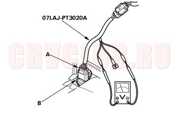
- Disconnect the 3P connector from the vehicle speed sensor (VSS) (A).
- Connect the test harness only to the engine wire harness.
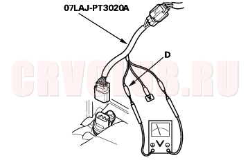
- Connect the RED test harness clip (B) to the positive probe of an ohmmeter. Cover the white (C) and green (D) test harness leads with protective tape (E).
- Check for continuity between the RED test harness clip and body ground.
Is there continuity?
Yes : Go to step 5.
No : Repair open in the BLK wire between the VSS and G101.
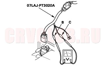
- Connect the WHT test harness clip (B) to the positive probe of a voltmeter, and connect the RED test harness clip (C) to the negative probe.
- Turn the ignition switch ON (II).
Is there battery voltage?
Yes : Go to step 7.
No : Repair open in the BLK/YEL wire between the VSS and the under-dash fuse/relay box.
- Disconnect the WHT test harness clip (B).
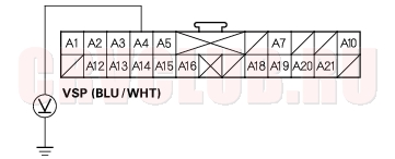
- Connect the GRN test harness clip (D) to the positive probe of a voltmeter.
Is there 5 V or battery voltage?
Yes : Go to step 9.
No : Repair short or open in the BLU/WHT [WHT/GRN] wire between the VSS and the ECM.
Vehicle Speed Signal Circuit Troubleshooting (cont'd) 22A-76
- Turn the ignition switch OFF.
- Connect the other test harness connector (A) to the VSS (B).
- Raise the front of the vehicle, and make sure it is securely supported.
- Put the vehicle in neutral with the ignition switch ON (II).
- Slowly rotate one wheel with the other wheel blocked.
Does the voltage pulse from 0 to about 5 V or battery voltage?
Yes : Go to step 14.
No : Replace the VSS.
- Touch the voltmeter positive probe to the gauge assembly A4 terminal, and connect the negative prove to body ground.
- Slowly rotate one wheel with the other wheel blocked.
Does the voltage pulse from 0 to about 5 V or battery voltage?
Yes : Replace the speedometer assembly.
No : Repair open in the BLU/WHT [WHT/GRN] wire between the VSS and the speedometer.
22A-77
A/T:
Before testing, check the No. 9 (10A) fuse in the under-hood fuse/relay box and the No. 10 (7.5A) fuse in the under-dash fuse/relay box.
Does the MIL come on and stay on?
Yes : Troubleshoot the PCM DTC (see page 11-62), and recheck.
No : Go to step 2.
- Check the multiplex control unit DTC (see page 22A-261) .
Is the DTC indicated?
Yes : Troubleshoot the DTC (see page 22A-261), and recheck.
No : Inspect the connector and socket terminals of the gauge assembly connectors. If the terminals look OK, substitute a known-good gauge assembly and reset. If the problem is fixed, replace the gauge assembly. If the problem is not fixed, replace the PCM.
VSS Replacement 22A-77
M/T only:
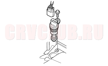
- Remove the air cleaner (see page 11-182) .
- Disconnect the 3P connector from the vehicle speed sensor (VSS).
- Remove the mounting bolt, then remove the VSS.
- Install the VSS in the reverse order of removal.
Outside Air Temperature Indicator Test 22A-78
NOTE: To test the outside air temperature sensor (see page 21-89) .
Troubleshooting:
If the indicator displays ''- - -'' for more than 2 seconds after selecting the outside air temperature display mode, check for an open in the wire between the gauge and the outside air temperature sensor.
Calibration:
The outside air temperature indicator's displayed temperature can be recalibrated ± 3° to meet the customer's expectations.
- Turn the ignition switch ON (II).
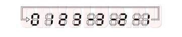
- Push and hold the trip/reset switch for 10 seconds. While you continue to hold the button, the display will scroll through temperature settings from +3° to -3° as shown.
- When the desired correction value appears on the display, release the buttons, and the recalibrated outside air temperature will be displayed.
- If the outside temperature indicator display is off by more than 3 degrees of the desired value, turn the ignition switch OFF and repeat steps 1-3.
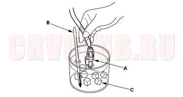
- NOTE: To recalibrate the display to the true temperature, remove the outside air temperature sensor (A), but leave it connected. Submerge the sensor and a thermometer (B) in a container of ice water (C). Select the calibration mode as described above, then recalibrate the display to the true temperature.
|
Body Electrical22A-1
Gauges 22A-64 |