Honda 2001 Body Electrical22A-1
Entry Light Control System 22A-111
Previous Page Next Page


Entry Light Control System 22A-111

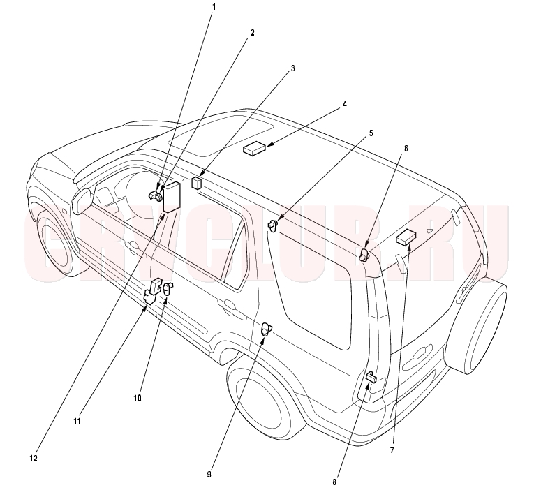
Component Location Index

NOTE: LHD type is shown, RHD type is similar.


1

IGNITION KEY SWITCH

Test, page 22A-123

2

IGNITION KEY LIGHT

Test, page 22A-124

3

KEYLESS RECEIVER UNIT

Input Test, page 22A-184

4

FRONT CEILING LIGHT

Test, page 22A-118 ; Replacement, page 22A-118

5

FRONT PASSENGER'S DOOR SWITCH

6

RIGHT REAR DOOR SWITCH

7

REAR CEILING LIGHT

Test, page 22A-118 ; Replacement, page 22A-118

8

TAILGATE SWITCH

Test, page 22A-120 ; Replacement, page 22A-120

9

LEFT REAR DOOR SWITCH

10

DRIVER'S DOOR SWITCH

11

DRIVER'S DOOR LOCK KNOB SWITCH

Test, page 22A-226

12

MULTIPLEX CONTROL UNIT

Input Test, page 22A-124


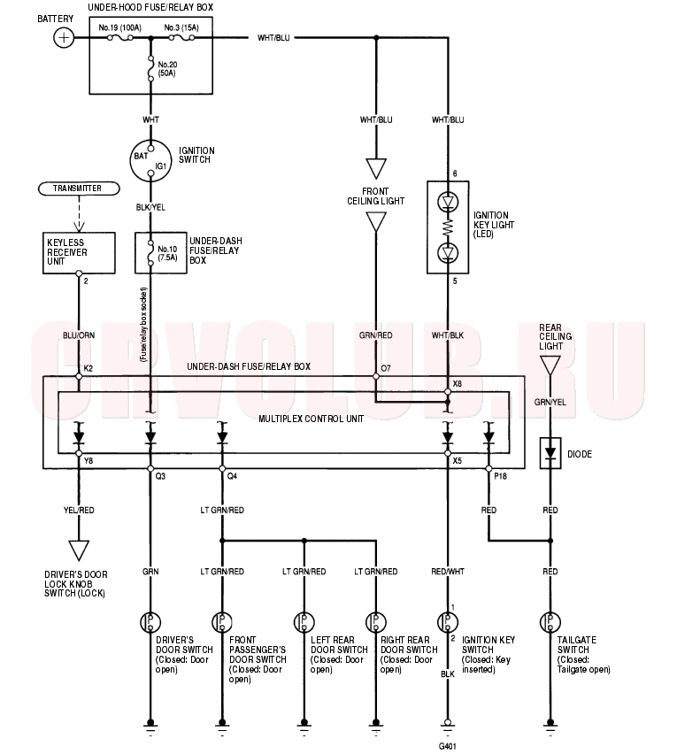
Circuit Diagram 22A-112


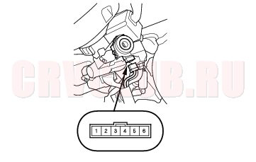
Ignition Key Switch Test 22A-113

NOTE: For more key-in beeper information, refer to the circuit diagram (see page 22A-122) and input test (see page 22A-124) .

When the ignition key is in the ignition switch, the key-in beeper circuit of multiplex control unit senses ground through the closed ignition key switch. When you open the driver's door, the beeper circuit senses ground through the closed door switch. When both switches are closed (driver's door and ignition), the key-in beeper in the gauge assembly is activated.

  1. Remove the steering column upper and lower covers (see page 17-24) .
  2. Disconnect the 6P connector.


  3. Check for continuity between the No. 1 and No. 2 terminals.
  4. There should be continuity with the key in the ignition switch.
  5. There should be no continuity with the key removed.
  6. If the continuity is not as specified, replace the steering lock assembly.

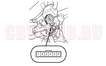
Ignition Key Light Test 22A-113

  1. Remove the steering column upper and lower covers (see page 17-24) .
  2. Disconnect the 6P connector.


  3. The LED should come on when power is connected to the No. 6 terminal and ground is connected to No. 5 terminal.

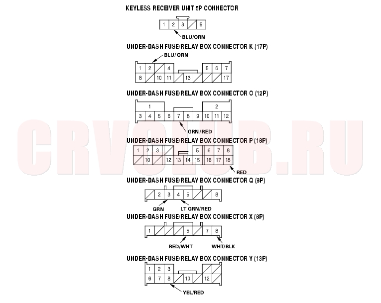
Control Unit Input Test 22A-114

  1. Before testing, troubleshoot the multiplex control system (see page 22A-269) .
  2. Remove the dashboard lower cover.
  3. Disconnect the under-dash fuse/relay box connectors.
  4. NOTE: All connectors are wire side of female terminals.


  5. Inspect the connector and socket terminals to be sure they are all making good contact.
  6. If the terminals are bent, loose or corroded, repair them as necessary, and recheck the system.
  7. If the terminals look OK, go to step 5.

22A-115

  1. With the connectors still disconnected, make these input tests at the connector.
  2. If any test indicates a problem, find and correct the cause, then recheck the system.
  3. If all the input tests prove OK, go to step 5.

    Cavity

    Wire

    Test condition

    Test: Desired result

    Possible cause if result is not obtained

    K2 BLU/ORN Under all conditions Check for continuity between the K2 terminal and the keyless receiver unit 5P connector No. 2 terminal: There should be continuity.
  4. An open in the wire
  5. X8 WHT/BLK Under all conditions Attach to ground: Ignition key light should come on.
  6. Blown No. 3 (15A) fuse in the under-hood fuse/relay box
  7. Faulty ignition key light
  8. An open in the wire


  9. Reconnect the connectors to the under-dash fuse/relay box, and make sure these input tests at the appropriate connectors on the under-dash fuse/relay box.
  10. If any test indicates a problem, find and correct the cause, then recheck the system.
  11. If all the input tests prove OK, the multiplex control unit must be faulty, replace the under-dash fuse/relay box assembly.

    Cavity

    Wire

    Test condition

    Test: Desired result

    Possible cause if result is not obtained

    P18 RED Tailgate lid open Check for voltage to ground: There should be 1 V or less.
  12. Faulty tailgate switch
  13. An open in the wire
  14. Tailgate closed Check for voltage to ground: There should be 5 V or more.
  15. Faulty tailgate switch
  16. Short to ground
  17. Q3 GRN Driver's door open Check for voltage to ground: There should be 1 V or less.
  18. Faulty driver's door switch
  19. An open in the wire
  20. Driver's door closed Check for voltage to ground: There should be 5 V or more.
  21. Faulty driver's door switch
  22. Short to ground
  23. Q4 LT GRN/ RED Front passenger's door open Check for voltage to ground: There should be 1 V or less.
  24. Faulty front passenger's door switch
  25. An open in the wire
  26. Front passenger's door closed Check for voltage to ground: There should be 5 V or more.
  27. Faulty front passenger's door switch
  28. Short to ground
  29. Left (right) rear door open Check for voltage to ground: There should be 1 V or less.
  30. Faulty left (right) rear door switch
  31. An open in the wire
  32. Left (right) rear door closed Check for voltage to ground: There should be 5 V or more.
  33. Faulty left (right) rear door switch
  34. Short to ground
  35. X5 RED/WHT Ignition key inserted into the ignition switch Check for voltage to ground: There should be 1 V or less.
  36. Poor ground (G401)
  37. Faulty ignition key switch
  38. An open in the wire
  39. Ignition key removed from the ignition switch Check for voltage to ground: There should be 5 V or more.
  40. Faulty ignition key switch
  41. Short to ground
  42. Y8 YEL/RED Driver's door lock knob switch locked Check for voltage to ground: There should be 1 V or less.
  43. Poor ground (G501)
  44. Faulty driver's door lock knob switch
  45. An open in the wire
  46. Driver's door lock knob switch unlocked Check for voltage to ground: There should be 5 V or more.
  47. Faulty driver's door lock knob switch
  48. Short to ground
  49. O7 GRN/RED Ceiling light switch in middle position, all door closed Attach to ground: Ceiling light(s) should come on.
  50. Blown No. 3 (15A) fuse in the under-hood fuse/relay box
  51. Blown bulb
  52. Faulty ceiling light
  53. An open in the wire


Honda 2001 Body Electrical22A-1
Entry Light Control System 22A-111
Previous Page Next Page