Multiplex Control System 22A-227
|
Body Electrical22A-1
Multiplex Control System 22A-227 |
Multiplex Control System 22A-227
Component Location Index
NOTE: LHD type is shown, RHD type is similar.
Test, page 22A-124 Troubleshooting, page 22A-261 ; Input Test, page 22A-269 Test, page 22A-118
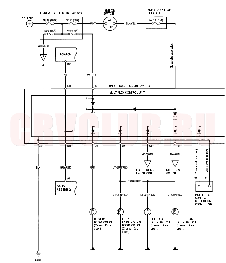
Circuit Diagram 22A-228
To page 22A-258
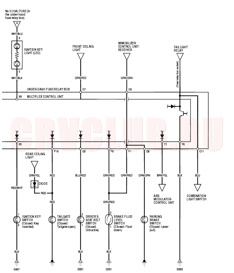
Circuit Diagram (cont'd) 22A-229
System Description 22A-230
The multiplex Control System has four internal functions:
Multiplexing (send multiple signals over shared wires) Wake up/sleep (runs at full power only on demand to reduce battery draw) Fail-safe (fixes or ignores faulty signals) Self-diagnosis (Mode 1 for system DTCs, Mode 2 for input lines) The system controls the function of these circuits:
Entry light control (ignition key light and ceiling light) Wiper/washer (intermittent wipe and park functions) Interlock system Keyless/power Door Lock Meter assembly, temperature gauge, and indicator lights HVAC (Compressor and fan control) Key-in reminder Lights-on reminder Seat belt reminder Daytime running lights Rear fog light Multiplex Communication
To reduce the number of wire harnesses, digital signals are sent via shared multiplex communication lines rather than sending normal electrical signals through individual wires.
The input signals from each switch are converted to digital signals at the central processing unit (CPU). The digital signals are sent from the transmitting unit to the receiving unit as serial signals. The transmitted signal is converted to a switch signal at the receiving unit, and it operates the related component or monitors a switch. There are exclusive communication lines between the ECM/PCM, the gauge assembly, and the under-dash fuse/relay box. Wake-up and Sleep
The multiplex control system has ''wake-up'' and ''sleep'' functions to decrease parasitic draw on the battery when the ignition switch is OFF.
In the sleep mode, the multiplex control unit stops functioning (communication and CPU control) when it is not necessary for the system to operate. As soon as any operation is requested (for example, a door is unlocked), the related control unit in the sleep mode immediately wakes up and begins to function. When the ignition switch is turned OFF, and the driver's or front passenger's door is opened, then closed, there is about a 40 second delay before the control unit goes from the wake-up mode to the sleep mode. If any door is open, the sleep mode will not function. If a key is in the ignition switch, the sleep mode will not function. When in sleep mode, the draw is reduced from 70-80 mA to less than 10 mA. Fail-safe
To prevent improper operation, the multiplex control system has a fail-safe function. In the fail-safe mode, the output signal is fixed when any part of the system malfunctions (for example a faulty control unit or communication line).
Each control unit has a hardware fail-safe function that fixes the output signal when there is any CPU malfunction, and a software fail-safe function that ignores the signal from the malfunctioning control unit and allows the system to operate normally.Troubleshooting 22A-231
Special Tool Required:
MPCS Service Connector 07WAZ-0010100
- Check the No. 9 (10 A) fuse in the under-hood fuse/relay box and the No. 10 (7.5 A) fuse in the under-dash fuse/relay box.
Are the fuses OK?
Yes : Go to step 2.
No : Find and repair the cause of the blown fuse.

- Remove the driver's dashboard lower cover (see page 20-88) .
- Switch the ceiling light to the middle position. Close all doors. Turn the ignition switch ON (II).
- If the driver's seatbelt is unbuckled, the beeper will beep five times.
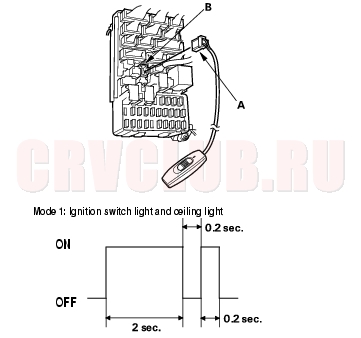
- Check self-diagnosis function Mode 1 for a diagnostic trouble code (DTC) by connecting the special tool (A) to the multiplex control inspection connector (B). After about 5 seconds, the ignition switch light and ceiling light should come on for 2 seconds, go out, then blink once for 0.2 second. This means that you are in Mode 1 of the self-diagnosis function.
Did the blinking lights confirm that you are in model?
Yes : Count the blinks, then go to step 5.
No : See if the SCS circuit is working properly. Go to step 6.
- If there is a DTC, it will blink, pause, then repeat the DTC as long as the ignition switch is ON (II).
Is there continuity?
Yes : Count the blinks, then go to step 8.
No : Go to step 9.
Is there continuity?
Yes : Go to step 9.
No : Go to step 7.
- Check for continuity between the connector J of under-dash fuse/relay box No. 4 terminal and body ground.
Is there continuity?
Yes : Faulty under-dash fuse/relay box. Replace and check for DTCs.
No : Repair the open in the wire, and recheck for DTCs.
Troubleshooting (cont'd) 22A-232
- About 1 second after you go into self-diagnosis mode 1, the ceiling light will indicate the DTC, and repeat it every 3 seconds. If there is more than one DTC, the system will indicate them in ascending order, beginning from the DTC with the lowest numerical value. Troubleshoot the DTCs as indicated below:
- DTC 1, 2, and 3 (ECM/PCM P0600) simultaneously: Check for a short to body ground in the YEL wire between multiplex control unit terminal E10 and ECM/PCM terminal E24, and in the GRY/RED wire between multiplex control unit terminal K10 and gauge assembly terminal A1. If both wires are OK, substitute a known-good multiplex control unit, gauge assembly, and ECM/PCM one at a time, in that order, and recheck for the DTCs after each substitution.
- DTC 2 and 5 simultaneously: Check for an open in the YEL wire between multiplex control unit terminal E10 and ECM/PCM terminal E24, If the wire is OK, substitute a known-good multiplex control unit, gauge assembly, and ECM/PCM one at a time, in that order, and recheck for the DTCs after each substitution.
- DTC 1, and 6 simultaneously: Check for an open in the GRY/RED wire between multiplex control unit terminal K10 and gauge assembly terminal A1, If the wire is OK, substitute a known-good multiplex control unit, gauge assembly, and ECM/PCM one at a time, in that order, and recheck for the DTCs after each substitution.
- DTC 1 only (no other DTCs present): Substitute a known-good multiplex control unit, and a gauge assembly one at a time, in that order, and recheck for the DTCs after each substitution.
- DTC 2 only (no other DTCs present): Substitute a known-good multiplex control unit and a ECM/PCM one at a time, in that order, and recheck for the DTCs after each substitution.
- DTC 3 only (no other DTCs present): Substitute a known-good multiplex control unit, and recheck for the DTC.
- DTC 5 only (no other DTCs present): Substitute a known-good gauge assembly, and recheck for the DTC.
- DTC 6 only (no other DTCs present): Update the ECM/PCM if it does not have the latest software, or substitute a known-good ECM/PCM, then recheck (see page 11-5) . If the symptom/indication goes away with a known-good ECM/PCM, replace the original ECM/PCM.
22A-233
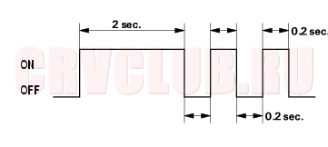
- From Mode 1, disconnect the special tool from the multiplex control inspection connector for about 5 to 10 seconds, then reconnect it. The ceiling light should come on for 2 seconds, then blink twice more at 0.2 second intervals. This means the system has gone from Mode 1 to Mode 2.
MODE 2: Ceiling Light Blinking Pattern
NOTE: To cancel Mode 2, disconnect the SCS service connector from the multiplex control inspection connector for more than 10 seconds or turn the ignition switch OFF.
- Look in the following table for the switches most closely related to the problem. While still in Mode 2, operate the switches and the control unit. If the circuit is OK, the spotlight and ceiling light should blink once. If the circuit is faulty, there will be no indication.
Does the ceiling light blink?
Yes : Go to step 12.
No : Go to step 11.
In each table below is a list of circuits that can be checked in Mode 2.
Does the spotlight and ceiling light blink for each circuit?
Yes : The additional circuits are OK. Repair the short or open in the circuit that failed the test in step 10.
No : Multiplex failed circuits can mean that the control unit has failed, but without triggering a DTC. Test a few more circuits. If they also fail, test the multiplex control unit inputs (see page 22A-269). If all the input test are OK, substitute a known-good control unit, gauge assembly, or ECM/PCM, one at a time, then recheck. If the system works properly, the original control unit is faulty; replace it. If there is still a malfunction, substitute a known-good control unit for the next most likely faulty control unit, then recheck. If the system works properly, that control unit is faulty; replace it.
Troubleshooting (cont'd) 22A-234
- Shift to the sleep mode:
Turn the ignition switch OFF, and remove the key.
If the control unit receivers no inputs from the inputs listed below, it will go into the sleep mode after about 20 seconds.
- Comfirm the sleep mode:
Check for voltage on the YEL and WHT/GRN wires. There should be battery voltage in the sleep mode. Check the parasitic draw at the battery while shifting into the sleep mode. Amperage should change from about 70 through 80 mA to less than 10 mA.
- Shift to the wake up mode:
- When the ignition switch is turned ON (II), the multiplex control unit, gauge assembly, and ECM/PCM wake up at the same time without ''talking'' to each other through the communication lines. When any switch in the multiplex system is turned on, it wakes up its related control unit which, in turn, wakes up the other units.
- After confirming the sleep mode, look in the following table for the switch most closely related to the problem. Operate that switch and see if its control unit wakes up.
- NOTE: If any control unit is faulty and will not wake up, several parts of the system will malfunction at the same time.
In the table below, the control unit is followed by a list of the switches and input signals that can wake it up.
Is the wake-up function OK?
Yes : Intermittent failure; the system is OK at this time.
No : Test the multiplex control unit inputs (see page 22A-269).
Multiplex Control Unit Input Test 22A-235
- Remove the dashboard under cover (see page 20-95) .
- Disconnect the under-dash fuse/relay box connectors C, E, F, J, K, O, P, Q, X and Y.
- NOTE: All connectors are wire side of female terminals.
- Inspect the connector and socket terminals to be sure they are all making good contact.
- If the terminals are bent, loose or corroded, repair them as necessary, and recheck the system.
- If the terminals look OK, go to step 4.
Multiplex Control Unit Input Test (cont'd) 22A-236
- Reconnect the connectors to the under-dash fuse/relay box, and make sure these input tests at the appropriate connectors on the under-dash fuse/relay box.
- If any test indicates a problem, find and correct the cause, then recheck the system.
- If all the input tests prove OK, the multiplex control unit must be faulty, replace the under-dash fuse/relay box assembly.
22A-237
|
Body Electrical22A-1
Multiplex Control System 22A-227 |