Keyless/Power Door Lock System 22A-158
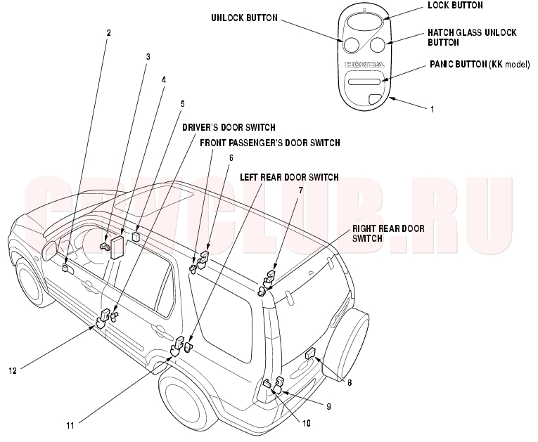
Component Location Index
NOTE: LHD type is shown, RHD type is similar.
|
1
|
TRANSMITTER
|
Test, page 22A-196
Programming, page 22A-197
|
|
7
|
RIGHT REAR DOOR LOCK ACTUATOR
|
Test, page 22A-193
|
|
2
|
DRIVER'S DOOR LOCK SWITCH
|
Test, page 22A-198
|
|
8
|
HATCH GLASS OPENER ACTUATOR
|
Test, page 22A-200
|
|
3
|
IGNITION KEY SWITCH
|
Test, page 22A-123
|
|
9
|
TAILGATE LOCK ACTUATOR
|
Test, page 22A-199
|
|
4
|
MULTIPLEX CONTROL UNIT
|
Input Test, page 22A-185
|
|
10
|
TAILGATE SWITCH
|
Test, page 22A-120
Replacement, page 22A-120
|
|
5
|
KEYLESS RECEIVER UNIT
|
Input Test, page 22A-184
|
|
11
|
LEFT REAR DOOR LOCK ACTUATOR
|
Test, page 22A-193
|
|
6
|
FRONT PASSENGER'S DOOR LOCK ACTUATOR
|
Test, page 22A-193
|
|
12
|
DRIVER'S DOOR LOCK ACTUATOR/KNOB SWITCH
|
Actuator Test, page 22A-193
Knob Switch Test, page 22A-226
|
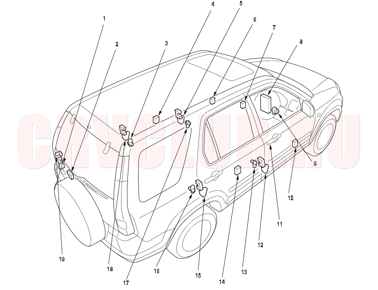
KE model:
|
1
|
TAILGATE LOCK ACTUATOR
|
Test, page 22A-199
|
|
10
|
DRIVER'S SUPER LOCKING CONTROL UNIT
|
Input Test, page 22A-191
|
|
TAILGATE KNOB SWITCH
|
Test, page 22A-231
|
|
11
|
DRIVER'S DOOR KEY CYLINDER SWITCH
|
Input Test, page 22A-230
|
|
2
|
HATCH GLASS OPENER ACTUATOR
|
Test, page 22A-200
|
|
12
|
DRIVER'S SUPER LOCKING ACTUATOR/KNOB SWITCH
|
Actuator Test, page 22A-193
Knob Switch Test, page 22A-226
|
|
3
|
LEFT REAR DOOR SWITCH
|
|
13
|
DRIVER'S DOOR SWITCH
|
|
4
|
LEFT REAR SUPER LOCKING CONTROL UNIT
|
Input Test, page 22A-191
|
|
14
|
RIGHT REAR SUPER LOCKING CONTROL UNIT
|
Input Test, page 22A-191
|
|
5
|
FRONT PASSENGER'S SUPER LOCKING ACTUATOR/KNOB SWITCH
|
Actuator Test, page 22A-193
Knob Switch Test, page 22A-226
|
|
15
|
RIGHT REAR SUPER LOCKING ACTUATOR/KNOB SWITCH
|
Actuator Test, page 22A-193
Knob Switch Test, page 22A-226
|
|
6
|
FRONT PASSENGER'S SUPER LOCKING CONTROL UNIT
|
Input Test, page 22A-191
|
|
16
|
RIGHT REAR DOOR SWITCH
|
|
7
|
KEYLESS RECEIVER UNIT
|
Input Test, page 22A-184
|
|
17
|
FRONT PASSENGER'S DOOR SWITCH
|
|
8
|
MULTIPLEX CONTROL UNIT
|
Input Test, page 22A-185
|
|
18
|
LEFT REAR SUPER LOCKING ACTUATOR/KNOB SWITCH
|
Actuator Test, page 22A-193
Knob Switch Test, page 22A-226
|
|
9
|
IGNITION KEY SWITCH
|
Test, page 22A-123
|
|
19
|
TAILGATE SWITCH
|
Test, page 22A-120
Replacement, page 22A-120
|
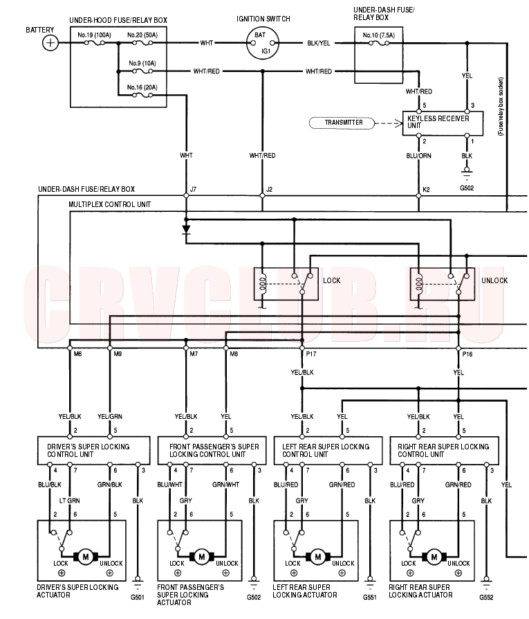
Circuit Diagram - With Super Locking 22A-160
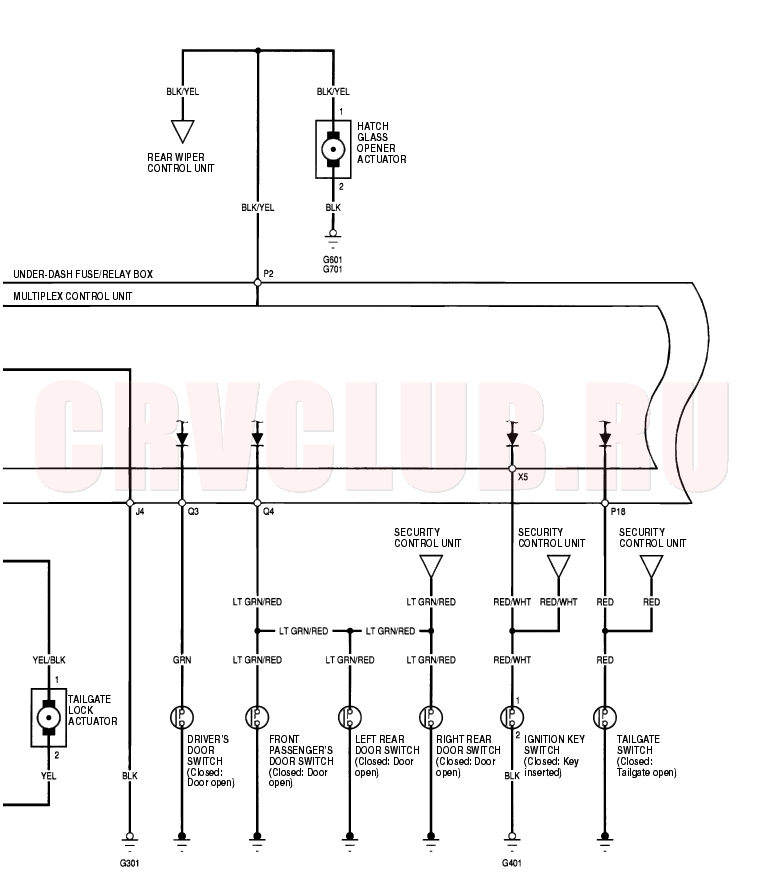
Circuit Diagram - With Super Locking (cont'd) 22A-162
Circuit Diagram - Without Super Locking 22A-163
Circuit Diagram - Without Super Locking (cont'd) 22A-164
Keyless Receiver Unit Input Test 22A-165
- Remove the heater control panel or climate control unit (see page 21-24)
.
- Disconnect the 5P connector (A) from the keyless receiver unit (B).
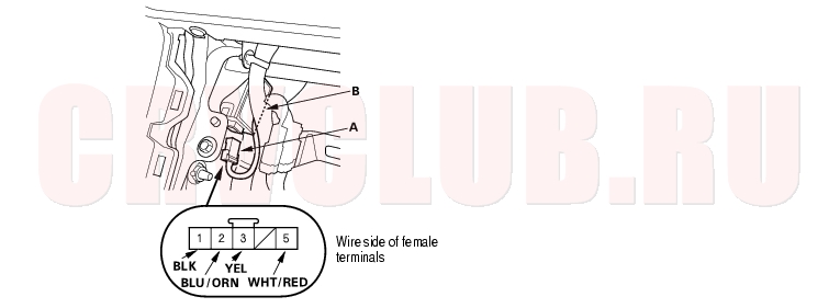
- Inspect the connector and socket terminals to be sure they are all making good contact.
- If the terminals are bent, loose or corroded, repair them as necessary, and recheck the system.
- If the terminals are OK, go to step 5.
- Reconnect the connector, and make these input tests at the connector.
- If any test indicates a problem, find and correct the cause, then recheck the system.
- If all the input tests prove OK, go to step 5.
|
|
|
|
Possible cause if result is not obtained
|
| 1
|
BLK
|
Under all conditions
|
Check for continuity to
ground:
There should be continuity.
|
- Poor ground (G502)
- An open in the wire
|
| 3
|
YEL
|
Ignition switch ON (II)
|
Check for voltage to ground:
There should be battery
voltage.
|
- Blown No. 10 (7.5A) fuse in the under-dash fuse/relay box
- An open in the wire
|
| Ignition switch OFF
|
Check for voltage to ground:
There should be no voltage.
|
- Short to power on No. 10 (7.5A) fuse circuit
|
| 5
|
WHT/RED
|
Under all conditions
|
Check for voltage to ground:
There should be battery
voltage.
|
- Blown No. 9 (10A) fuse in the under-hood fuse/relay box
- An open in the wire
|
- Disconnect the connector, and make this input test at the connector.
- If the test indicates a problem, find and correct the cause, then recheck the system.
- If the input test prove OK, replace the keyless receiver unit.
|
|
|
|
Possible cause if result is not obtained
|
| 2
|
BLU/ORN
|
Ignition switch OFF,
under-dash fuse/relay
box connector K (17P)
disconnected
|
Check for continuity between
the No. 2 terminal and the No.
2 terminal of the under-dash
fuse/relay box connector K
(17P).
There should be continuity.
|
- An open in the wire
- A short to ground in the wire
|
| Check for continuity between
the No. 2 terminal and body
ground:
There should be no
continuity.
|
Control Unit Input Test - Without Super Locking 22A-166
NOTE: For the hatch glass unlock button test, refer to the rear wiper control unit input test (see page 22A-246)
.
- Before testing, troubleshoot the multiplex control system (see page 22A-261)
.
- Remove the dashboard lower cover.
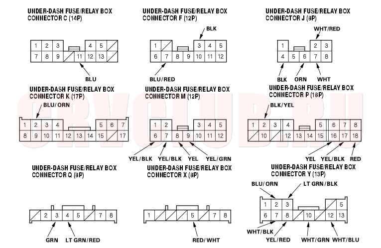
- Disconnect the under-dash fuse/relay box connectors.
- NOTE: All connectors are wire side of female terminals.
- Inspect the connector and socket terminals to be sure they are all making good contact.
- If the terminals are bent, loose or corroded, repair them as necessary, and recheck the system.
- If the terminals look OK, go to step 5.
- With the connectors still disconnected, make these input tests at the connector.
- If any test indicates a problem, find and correct the cause, then recheck the system.
- If all the input tests prove OK, go to step 6.
|
|
|
|
Possible cause if result is not obtained
|
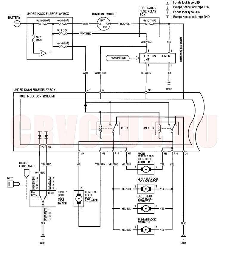
| J4
|
BLK
|
Under all conditions
|
Check for continuity to
ground:
There should be continuity.
|
- Poor ground (G301)
- An open in the wire
|
| J2
|
WHT/RED
|
Under all conditions
|
Check for voltage to ground:
There should be battery
voltage.
|
- Blown No. 9 (10A) fuse in the under-hood fuse/relay box
- An open in the wire
|
| J7
|
WHT
|
Under all conditions
|
Check for voltage to ground:
There should be battery
voltage.
|
- Blown No. 16 (20A) fuse in the under-hood fuse/relay box
- An open in the wire
|
| M7
|
YEL/BLK
|
Connect J7 terminal to
M6 [or M9] terminal, and
M9 [or M6] terminal to F3
terminal.
|
Check actuator operation:
The driver's door lock
actuator should lock [or
unlock].
|
- Blown No. 16 (20A) fuse in the under-hood fuse/relay box
- Faulty driver's door lock actuator
- An open in the wire
|
| M9
|
YEL/GRN
|
| M6
|
YEL/BLK
|
Connect J7 terminal to
M7 [or M8] terminal, and
M8 [or M7] terminal to F3
terminal.
|
Check actuator operation:
The front passenger's door
lock actuator should lock [or
unlock].
|
- Blown No. 16 (20A) fuse in the under-hood fuse/relay box
- Faulty front passenger's door lock actuator
- An open in the wire
|
| M8
|
YEL
|
| P16
|
YEL
|
Connect J7 terminal to
P17 [or P16] terminal,
and P16 [or P17] terminal
to F3 terminal.
|
Check actuator operation:
The both rear door lock
actuator should lock [or
unlock].
|
- Blown No. 16 (20A) fuse in the under-hood fuse/relay box
- Faulty left or right door lock actuator
- An open in the wire
|
| P17
|
YEL/BLK
|
| K2
|
BLU/ORN
|
Under all conditions
|
Check for continuity between
the K2 terminal and the
keyless receiver unit 5P
connector No. 2 terminal with
5P connector disconnected:
There should be continuity.
|
- An open in the wire
|
| Y2*
|
BLU/ORN
|
Under all conditions
|
Check for continuity between
the Y2 terminal and the
security control unit A17
terminal with the security
control unit 20P connector
disconnected:
There should be continuity.
|
- An open in the wire
|
| Y3*
|
LT GRN/
BLK
|
Under all conditions
|
Check for continuity between
the Y3 terminal and the
security control unit A6
terminal with the security
control unit 20P connector
disconnected:
There should be continuity.
|
- An open in the wire
|
- *: With security system
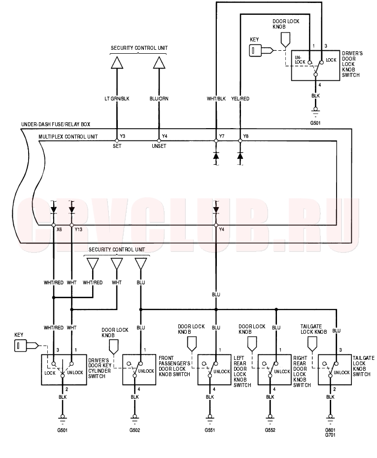
Control Unit Input Test - Without Super Locking (cont'd) 22A-168
- Reconnect all connections to the under-dash fuse/relay box, and make sure these input tests at the appropriate connectors on the under-dash fuse/relay box.
- If any test indicates a problem, find and correct the cause, then recheck the system.
- If all the input tests prove OK, the multiplex control unit must be faulty, replace the under-dash fuse/relay box assembly.
|
|
|
|
Possible cause if result is not obtained
|
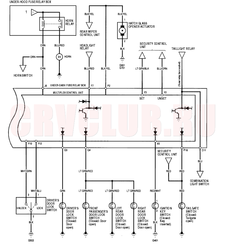
| P18
|
RED
|
Tailgate open
|
Check for voltage to ground:
There should be 1 V or less.
|
- Poor ground (G601 or G553)
- Faulty trunk or tailgate switch
- An open in the wire
|
| Tailgate closed
|
Check for voltage to ground:
There should be 5 V or more.
|
- Faulty trunk switch
- Short to ground
|
| Q3
|
GRN
|
Driver's door open
|
Check for voltage to ground:
There should be 1 V or less.
|
- Faulty driver's door switch
- An open in the wire
|
| Driver's door closed
|
Check for voltage to ground:
There should be 5 V or more.
|
- Faulty driver's door switch
- Short to ground
|
| Q4
|
LT GRN/
RED
|
Passenger's door open
|
Check for voltage to ground:
There should be 1 V or less.
|
- Faulty passenger's door switch
- An open in the wire
|
| Passenger's door closed
|
Check for voltage to ground:
There should be 5 V or more.
|
- Faulty passenger's door switch
- Short to ground
|
| X5
|
RED/WHT
|
Ignition key inserted into
the ignition switch
|
Check for voltage to ground:
There should be 1 V or less.
|
- Poor ground (G401)
- Faulty ignition key switch
- An open in the wire
|
| Ignition key removed
from the ignition switch
|
Check for voltage to ground:
There should be 5 V or more.
|
- Faulty ignition key switch
- Short to ground
|
| Y7
|
WHT/BLK
|
Driver's door lock knob
switch unlocked
|
Check for voltage to ground:
There should be less than 1
V.
|
- Poor ground (G501)
- Faulty driver's door lock knob switch
- An open in the wire
|
| Driver's door lock knob
switch locked
|
Check for voltage to ground:
There should be 5 V or more.
|
- Faulty driver's door lock knob switch
- Short to ground
|
| Y8
|
YEL/RED
|
Driver's door lock knob
switch locked
|
Check for voltage to ground:
There should be 1 V or less.
|
- Poor ground (G501)
- Faulty driver's door lock knob switch
- An open in the wire
|
| Driver's door lock knob
switch unlocked
|
Check for voltage to ground:
There should be 5 V or more.
|
- Faulty driver's door lock knob switch
- Short to ground
|
| Y10
|
WHT/GRN
|
Driver's door lock switch
unlocked
|
Check for voltage to ground:
There should be 1 V or less.
|
- Poor ground (G501)
- Faulty driver's door lock switch
- An open in the wire
|
| Driver's door lock switch
in neutral
|
Check for voltage to ground:
There should be 5 V or more.
|
- Faulty driver's door lock switch
- Short to ground
|
| Y12
|
WHT/BLU
|
Driver's door lock switch
locked
|
Check for voltage to ground:
There should be 1 V or less.
|
- Poor ground (G501)
- Faulty driver's door lock switch
- An open in the wire
|
| Driver's door lock switch
in neutral
|
Check for voltage to ground:
There should be 5 V or more.
|
- Faulty driver's door lock switch
- Short to ground
|
| P2
|
BLK/YEL
|
Press the keyless
transmitter hatch glass
unlock button
|
Check for voltage to ground:
There should be battery
voltage for a moment.
|
- Poor ground (G601, G701)
- Faulty hatch glass opener actuator
- An open in a wire
|
| C11
|
BLU
|
Under all conditions
|
Attach to ground:
Parking, side marker, license
plate lights and taillights
should come on.
|
- Blown No. 2 (15A) fuse in the under-hood fuse/relay box
- Faulty taillight relay
- Faulty under-dash fuse/relay box
- An open in the wire
|
| F7
|
BLU/RED
|
Under all conditions
|
Attach to ground:
Headlights should come on.
|
- Blown No. 15 or 17 (15A) fuse in the under-hood fuse/relay box
- Faulty headlight relay 1 or 2
- An open in the wire
|
| J6
|
ORN
|
Under all conditions
|
Attach to ground:
The horn should sound.
|
- Blown No. 7 (15A) fuse in the under-hood fuse/relay box
- Faulty horn relay
- Faulty horn
- An open in the wire
|
Control Unit Input Test - With Super Locking 22A-169
NOTE: For the hatch glass unlock button test, refer to the rear wiper control unit input test (see page 22A-246)
.
- Before testing, troubleshoot the multiplex control system (see page 22A-261)
.
- Remove the dashboard lower cover.
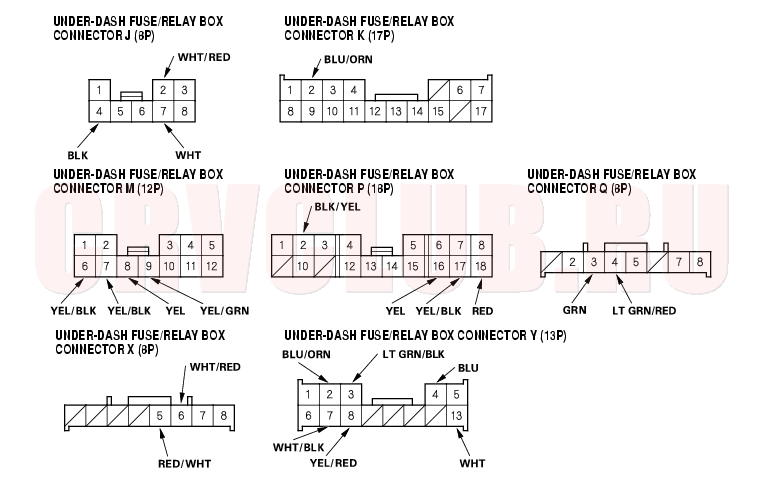
- Disconnect the under-dash fuse/relay box connectors.
- NOTE: All connectors are wire side of female terminals.
- Inspect the connector and socket terminals to be sure they are all making good contact.
- If the terminals are bent, loose or corroded, repair them as necessary, and recheck the system.
- If the terminals look OK, go to step 5.
Control Unit Input Test - With Super Locking (cont'd) 22A-170
- Reconnect the connectors, and make these input tests at the connector.
- If any test indicates a problem, find and correct the cause, then recheck the system.
- If all the input tests prove OK, go to step 6.
|
|
|
|
Possible cause if result is not obtained
|
| J2
|
WHT/RED
|
Under all conditions
|
Check for voltage to ground:
There should be battery
voltage.
|
- Blown No. 9 (10A) fuse in the under-hood fuse/relay box
- An open in the wire
|
| J7
|
WHT
|
Under all conditions
|
Check for voltage to ground:
There should be battery
voltage.
|
- Blown No. 16 (20A) fuse in the under-hood fuse/relay box
- An open in the wire
|
| K2
|
BLU/ORN
|
Under all conditions
|
Check for continuity between
the K2 terminal and the
keyless receiver unit 5P
connector No. 2 terminal with
the 5P connector
disconnected:
There should be continuity.
|
- An open in the wire
|
| M6
|
YEL/BLK
|
Connect J7 terminal to
M7 [or M8] terminal, and
M8 [or M7] terminal to F3
terminal.
|
Check actuator operation:
The front passenger's door
lock actuator should lock [or
unlock].
|
- Blown No. 16 (20A) fuse in the under-hood fuse/relay box
- Faulty actuator
- Faulty super locking control unit
- An open in the wire
|
| M8
|
YEL
|
| M7
|
YEL/BLK
|
Connect J7 terminal to
M6 [or M9] terminal, and
M9 [or M6] terminal to F3
terminal.
|
Check actuator operation:
The driver's door lock
actuator should lock [or
unlock].
|
- Blown No. 16 (20A) fuse in the under-hood fuse/relay box
- Faulty actuator
- Faulty super locking control unit
- An open in the wire
|
| M9
|
YEL/GRN
|
| P17
|
YEL/BLK
|
Connect J7 terminal to
P17 [or P16] terminal,
and P16 [or P17] terminal
to F3 terminal.
|
Check actuator operation:
The left rear door, right rear
door and tailgate lock
actuator should lock [or
unlock].
|
- Blown No. 16 (20A) fuse in the under-hood fuse/relay box
- Faulty actuator
- Faulty left rear or right rear super locking control unit.
- An open in the wire
|
| P16
|
YEL
|
| J4
|
BLK
|
Under all conditions
|
Check for continuity to
ground:
There should be continuity.
|
- Poor ground (G301)
- An open in the wire
|
- Reconnect all connector to the under-dash fuse/relay box, and make sure these input tests at the appropriate connectors on the under-dash fuse/relay box.
- If any test indicates a problem, find and correct the cause, then recheck the system.
- If all the input tests prove OK, the multiplex control unit must be faulty, replace the under-dash fuse/relay box assembly.
|
|
|
|
Possible cause if result is not obtained
|
| P18
|
RED
|
Tailgate open
|
Check for voltage to ground:
There should be 1 V or less.
|
- Poor ground (G601)
- Faulty tailgate latch switch
- An open in the wire
|
| Tailgate closed
|
Check for voltage to ground:
There should be 5 V or more.
|
| X5
|
RED/WHT
|
Ignition key inserted into
the ignition switch
|
Check for voltage to ground:
There should be 1 V or less.
|
- Poor ground (G401)
- Faulty ignition key switch
- An open in the wire
|
| Ignition key removed
from the ignition switch
|
Check for voltage to ground:
There should be 5 V or more.
|
| Q3
|
GRN
|
Driver's door open
|
Check for voltage to ground:
There should be 1 V or less.
|
- Faulty driver's door switch
- An open in the wire
|
| Driver's door closed
|
Check for voltage to ground:
There should be 5 V or more.
|
| Q4
|
LT GRN/
RED
|
Passengers door open
|
Check for voltage to ground:
There should be 1 V or less.
|
- Faulty passenger's door switch
- An open in the wire
|
| Passenger's door closed
|
Check for voltage to ground:
There should be 5 V or more.
|
| Y4
|
BLU
|
Front passenger's,
tailgate, left rear or right
rear door lock knob
switch unlocked
|
Check for voltage to ground:
There should be 1 V or less.
|
- Faulty front passenger's, tailgate, left rear or right rear door lock knob switch
- Poor ground (G502, G551, G552, G601, G701)
- An open in the wire
|
| X6
|
WHT/RED
|
Driver's door key cylinder
switch lock
|
Check for voltage to ground:
There should be 1 V or less.
|
- Faulty driver's door key cylinder switch
- Poor ground (G501)
- An open in the wire
|
| Driver's door key cylinder
switch in neutral
|
Check for voltage to ground:
There should be 5 V or more.
|
| Y13
|
WHT
|
Driver's door key cylinder
switch unlocked
|
Check for voltage to ground:
There should be 1 V or less.
|
| Driver's door key cylinder
switch in neutral
|
Check for voltage to ground:
There should be 5 V or more.
|
| Y7
|
WHT/BLK
|
Driver's door lock knob
switch unlocked
|
Check for voltage to ground:
There should be less than 1
V.
|
- Poor ground (G501)
- Faulty driver's door lock knob switch
- An open in the wire
|
| Driver's door lock knob
switch locked
|
Check for voltage to ground:
There should be 5 V or more.
|
- Faulty driver's door lock knob switch
- Short to ground
|
| Y8
|
YEL/RED
|
Driver's door lock knob
switch locked
|
Check for voltage to ground:
There should be 1 V or less.
|
- Poor ground (G501)
- Faulty driver's door lock knob switch
- An open in the wire
|
| Driver's door lock knob
switch unlocked
|
Check for voltage to ground:
There should be 5 V or more.
|
- Faulty driver's door lock knob switch
- Short to ground
|
| Y2
|
BLU/ORN
|
Under all conditions
|
Check for continuity between
the Y2 terminal and the
security control unit A17
terminal with the security
control unit 20P connector
disconnected:
There should be continuity.
|
- An open in the wire
|
| Y3
|
LT GRN/
BLK
|
Under all conditions
|
Check for continuity between
the Y3 terminal and the
security control unit A6
terminal with the security
control unit 20P connector
disconnected:
There should be continuity.
|
- An open in the wire
|
| P2
|
BLK/YEL
|
Press the keyless
transmitter hatch glass
unlock button
|
Check for voltage to ground:
There should be battery
voltage for a moment.
|
- Poor ground (G601, G701)
- Faulty hatch glass opener actuator
- An open in a wire
|
Super Locking Control Unit Input Test 22A-172
- Remove the each door panel (see page 20-6)
.
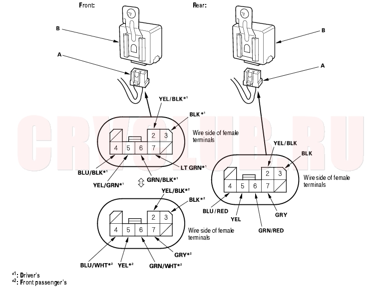
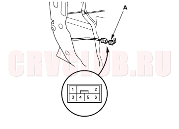
- Disconnect the 8 P connector (A) from the super locking control unit (B).
- Inspect the connector and socket terminals to be sure they are all making good contact.
- If the terminals are bent, loose or corroded, repair them as necessary, and recheck the system.
- If the terminals look OK, make the following input tests at the connector.
- If a test indicates a problem, find and correct the cause, then recheck the system.
- If all the input tests prove OK, the control unit must be faulty, replace it.
|
|
|
|
Possible cause if result is not obtained
|
| 3
|
BLK
|
Under all conditions
|
Check for continuity to
ground:
There should be continuity.
|
Poor ground (G501, G502, G551, G552)
An open in the wire
|
| 2
|
YEL/BLK
|
Connect the No. 2
terminal to the No. 7
terminal and the No. 6
terminal to the No. 3
terminal momentarily with
ignition switch ON (II)
|
Check actuator operation:
The actuator should lock.
|
Faulty door lock actuator
An open in the wire
|
| 7
|
LT GRN
[GRY]
|
| 5
|
YEL/GRN
[YEL]
|
Connect the No. 5
terminal to the No. 6
terminal and the No. 7
terminal to the No. 3
terminal momentarily with
ignition switch ON (II)
|
Check actuator operation:
The actuator should unlock.
|
| 6
|
GRN/BLK
[GRN/WHT
or GRN/
RED]
|
| 4
|
BLU/BLK
[BLU/WHT
or BLU/
RED]
|
Under all conditions
|
Check for continuity between
the No. 4 terminal and No. 2
terminal of the actuator.
There should be continuity.
|
An open in the wire
|
[ ]: Passenger's
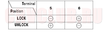
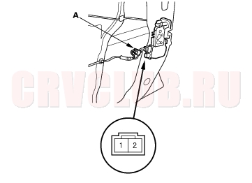
Door Lock Actuator Test 22A-174
Driver's Door without Super Locking:
- Remove the driver's door panel (see page 20-9)
.
- Disconnect the 2P connector (A) from the actuator.
- Check actuator operation by connecting power and ground according to the table. To prevent damage to the actuator, apply battery voltage only momentarily.
- If the actuator does not work as specified, replace it.
Driver's Door with Super Locking:
- Remove the driver's door panel (see page 20-9)
.
- Disconnect the 6P connector (A) from the actuator.
- Check actuator operation by connecting power and ground according to the table. To prevent damage to the actuator, apply battery voltage only momentarily.
- If the actuator does not work as specified, replace it.
Passenger's Door without Super Locking:
- Remove the passenger's door panel (see page 20-9)
.
- Disconnect the 2P connector (A) from the actuator.
- Check actuator operation by connecting power and ground according to the table. To prevent damage to the actuator, apply battery voltage only momentarily.
- If the actuator does not work as specified, replace it.
Passenger's Door with Super Locking:
- Remove the passenger's door panel (see page 20-9)
.
- Disconnect the 6P connector (A) from the actuator.
- Check actuator operation by connecting power and ground according to the table. To prevent damage to the actuator, apply battery voltage only momentarily.
- If the actuator does not work as specified, replace it.
Transmitter Test 22A-176
NOTE:
If the doors unlock or lock with the transmitter, but the LED on the transmitter does not come on, the LED is faulty; replace the transmitter.
If any door is open, you cannot lock the door with the transmitter.
If you unlocked the doors with the transmitter, but do not open any of the doors within 30 seconds, the doors relock automatically.
The doors do not lock or unlock with the transmitter if the ignition key is in the ignition switch.
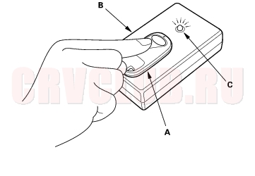
Using a keyless entry checker (07MAJ-SP00300):
Put the transmitter (A) on the keyless entry checker (B) and press the button.
If the ray indicator light (C) does not come on, check for:
a dead or low battery.
faulty transmitter.
If the ray indicator light comes on, the transmitter is OK.
NOTE: When the transmitter battery was replaced, aim the transmitter at the receiver, and press the transmitter button six times. The receiver is located behind the center lower panel. Confirm you can hear the sound of the door lock actuators when you press the sixth time.
Transmitter Programming 22A-176
Storing transmitter codes:
The codes of up to three transmitters can be programmed into the keyless receiver unit memory. (If a fourth code is stored, the code that was programmed first will be erased.)
NOTE: It is important to maintain the time limits between the steps. Make sure the doors and the tailgate are closed.
- Turn the ignition switch ON (II).
- Within 1 to 4 seconds, push the transmitter lock or unlock button.
- Within 1 to 4 seconds, turn the ignition switch OFF.
- Within 1 to 4 seconds, turn the ignition switch ON (II).
- Within 1 to 4 seconds, push the transmitter lock or unlock button.
- Within 1 to 4 seconds, turn the ignition switch OFF.
- Within 4 seconds, turn the ignition switch ON (II).
- Within 1 to 4 seconds, push the transmitter lock or unlock button.
- Within 1 to 4 seconds, turn the ignition switch OFF.
- Within 4 seconds, turn the ignition switch ON (II).
- Within 1 to 4 seconds, push the transmitter lock or unlock button.
- Confirm you can hear the sound of the door lock actuators. Within 1 to 4 seconds, push the transmitter lock or unlock button again.
- Within 10 seconds, press the transmitter lock or unlock buttons on the two additional transmitters. Confirm that you can hear the sound of the door lock actuators after each transmitter code is stored.
- Turn the ignition switch OFF, and remove the key.
- Confirm proper operation of the transmitters.
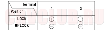
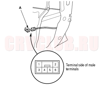
Door Lock Switch Test 22A-177
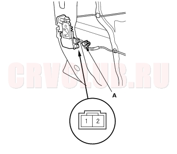
- Remove the door panel (see page 20-9)
.
- Remove the two mounting screws and the door lock switch.
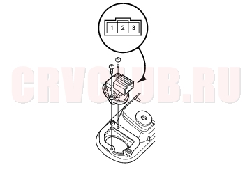
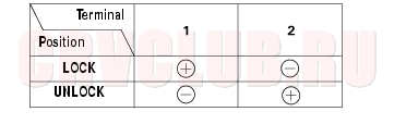
- Check for continuity between the No. 1 and No. 2 terminals:
- There should be continuity when the door lock switch is in the LOCKED position.
- There should be no continuity when the door lock switch is in the UNLOCKED position.
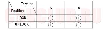
- Check for continuity between the No. 2 and No. 3 terminals:
- There should be continuity when the door lock switch is in the UNLOCKED position.
- There should be no continuity when the door lock switch is in the LOCKED position.
- If the continuity is not as specified, replace the door lock switch.
Tailgate Lock Actuator Test 22A-178
- Remove the tailgate lower trim panel (see page 20-80)
.
- Disconnect the 2P connector from the actuator.
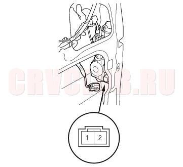
- Check actuator operation by connecting power and ground according to the table. To prevent damage to actuator, apply battery voltage only momentarily.
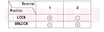
- If the actuator does not operate as specified, replace it.
Hatch Glass Opener Actuator Test 22A-178
- Remove the tailgate lower trim panel (see page 20-80)
.
- Disconnect the 2P connector from the actuator.
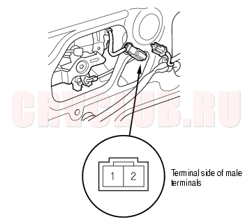
- Connect power to the No. 1 terminal and ground to the No. 2 terminals momentarily. The actuator should operate.
- If the actuator does not operate as specified, replace it.