ABS Components19B-2
|
Brakes19B-1
ABS Components19B-2 |
ABS Components19B-2
Special Tools
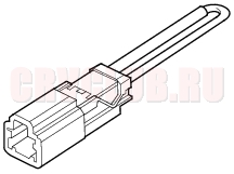
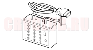
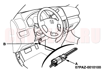
07PAZ-0010100 SCS Short Connector (EU model) 1 07WAJ-0010100 DLC Pin Box (Except EU model) 1
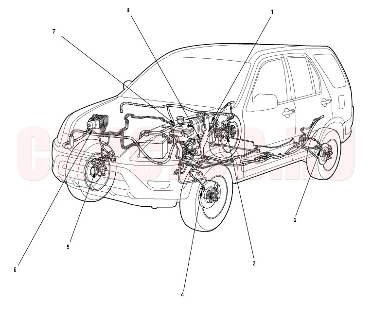
Component Location Index19B-3
Inspection, page 19B-38 Replacement, page 19B-39 Inspection, page 19B-38 Replacement, page 19B-39 Removal and installation, page 19B-36 Inspection, page 19B-38 Replacement, page 19B-39 Inspection, page 19B-38 Replacement, page 19B-39
General Troubleshooting Information19B-4
ABS Indicator
If the system is OK, the ABS indicator goes off 2 seconds after turning the ignition switch ON (II) without starting the engine, and then comes on again and goes off 2 seconds later after starting the engine. This occurs because the ABS control unit is turned on by the IG1 power source. The ABS indicator comes on when the ABS control unit detects a problem in the system. However, even though the system is operating properly, the indicator will come on under these conditions:
Only the drive wheels rotate One drive wheel is stuck The vehicle goes into a spin The ABS continues to operate for a long time. The vehicle is subjected to an electrical signal disturbance To determine the actual cause of the problem, question the customer about the problem, taking the above conditions into consideration.
When a problem is detected and the ABS indicator comes on, there are cases when the indicator stays on until the ignition switch is turned OFF, and cases when the indicator goes off automatically when the system returns to normal.
DTC 61, 62:
The ABS indicator goes off automatically when the system returns to normal.DTC 11, 13, 15, 17, 31, 32, 33, 34, 35, 36, 37, 38, 54, or 81:
The ABS indicator stays on until the ignition switch is turned OFF whether or not the system returns to normal.DTC 12, 14, 16, 18, 21, 22, 23, 24, 51, 52, or 53:
The ABS indicator goes off when the vehicle is driven again and the system is OK after the ignition switch is turned from OFF to ON (II).Diagnostic Trouble Code (DTC)
The memory can hold three DTCs. However, when the same DTC is detected more than once, the more recent DTC is written over the earlier one.
Therefore, when the same problem is detected repeatedly, it is memorized as a single DTC.The DTCs are indicated in the order they occurred, beginning with the most recent. The DTCs are memorized in the EEPROM (non-volatile memory). Therefore, the memorized DTCs are not cleared when the battery is disconnected, the ignition switch is turned off, or the system returns to normal. Perform the specified procedures to clear the DTCs. Self-diagnosis
Self-diagnosis can be classified into two categories:
Initial diagnosis:
Done right after the engine starts and until the ABS indicator goes offRegular diagnosis:
Done right after the initial diagnosis until the ignition switch is turned OFFWhen a problem is detected by self-diagnosis, the system does the following:
Turns the ABS indicator on Memorizes the DTC Stops ABS control Kickback
The pump motor operates when the ABS is functioning, and the fluid in the reservoir is forced out to the master cylinder, causing kickback at the brake pedal.
Pump Motor
The pump motor operates when the ABS is functioning. The ABS control unit checks the pump motor operation when the vehicle is started the first time after the ignition switch is turned ON (II). You may hear the motor operate at this time, but it is normal. 19B-5
How to Troubleshoot ABS DTCs
The troubleshooting flowchart procedures assume that the cause of the problem is still present and the ABS indicator is still on. Following the flowchart when the ABS indicator does not come on can result in incorrect diagnosis.
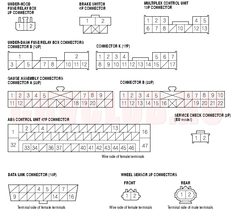
The connector illustrations show the female terminal connectors with a single outline and the male terminal connectors with a double outline.
- Question the customer about the conditions when the problem occured, and try to reproduce the same conditions for troubleshooting. Find out when the ABS indicator came on, such as during ABS control, after ABS control, when the vehicle was at a certain speed, etc.
- When the ABS indicator does not come on during the test-drive, but troubleshooting is done based on the DTC, check for loose connectors, poor terminal contact, etc., before you start troubleshooting.
- After troubleshooting, clear the DTC and test-drive the vehicle. Be sure the ABS indicator does not come on.
How to Retrieve ABS DTCs
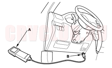
Honda PGM Tester Method:
- With the ignition switch OFF, connect the Honda PGM Tester (A) to the 16P Data Link Connector (DLC) (B) right side of the under-dash fuse/relay box.
- Turn the ignition switch ON (II), and follow the prompts on the PGM Tester to display the DTC(s) on the screen. After determining the DTC, refer to the DTC Troubleshooting Index.
- NOTE: See the Honda PGM Tester user's manual for specific instructions.
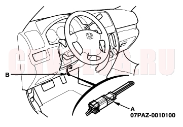
SCS Short Connector Method (EU Model):
- With the ignition switch OFF, connect the SCS short connector (A) to the service check connector (2P) (B) right side of the under-dash fuse/relay box.
- Turn the ignition switch ON (II) without pressing the brake pedal.
- NOTE: If you press the brake pedal when turning the ignition switch ON (II), the system shifts to the DTC clearing mode.
General Troubleshooting Information (cont'd)19B-6
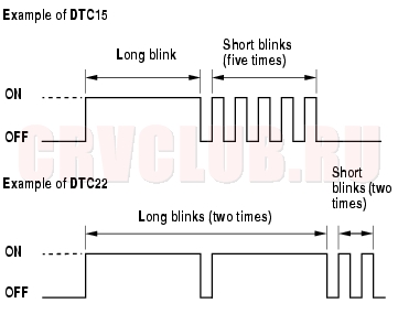
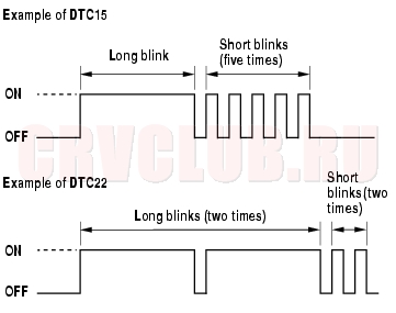
- The blinking frequency indicates the DTC. DTCs are indicated by a series of long and short blinks. One long blink equals 10 short blinks. Add the long and short blinks together to determine the DTC. After determining the DTC, refer to the DTC Troubleshooting Index.
If the DTC is not memorized, the ABS indicator will go off for 3.6 seconds, and then come back on. If the ABS indicator continues on, troubleshoot for ''ABS indicator does not go off'' (see step 1 on page 19B-33 ). The system will not indicate the DTC unless these conditions are met: The ignition switch is turned ON (II). The SCS circuit is shorted to body ground before the ignition switch is turned ON (II).
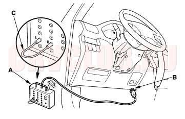
DLC Pin Box Method (Except EU Model):
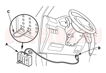
- With the ignition switch OFF, connect the DLC pin box (A) to the 16P Data Link Connector (DLC) (B) right side of the under-dash fuse/relay box.
- Insert the plugs of the jumper wire (C) to No. 4 and No. 9 plug holes of the DLC terminal box, then push the switch.
- Turn the ignition switch ON (II) without pressing the brake pedal.
- NOTE: If you press the brake pedal when turning the ignition switch ON (II), the system shifts to the DTC clearing mode.
19B-7
- The blinking frequency indicates the DTC. DTCs are indicated by a series of long and short blinks. One long blink equals 10 short blinks. Add the long and short blinks together to determine the DTC. After determining the DTC, refer to the DTC Troubleshooting Index.
If the DTC is not memorized, the ABS indicator will go off for 3.6 seconds, and then come back on. If the ABS indicator stays on, troubleshoot for ''ABS indicator does not go off'' (see step 1 on page 19B-33 ). The system will not indicate the DTC unless these conditions are met: The brake pedal is not pressed. The ignition switch is turned ON (II). The SCS circuit is shorted to body ground before the ignition switch is turned ON (II).
How to Clear ABS DTCs
Honda PGM Tester Method:
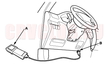
- With the ignition switch OFF, connect the Honda PGM Tester (A) to the 16P Data Link Connector (DLC) (B) under the driver's side of the dashboard.
- Turn the ignition switch ON (II), and clear the DTC(s) by following the screen prompts on the PGM Tester.
- NOTE: See the Honda PGM Tester user's manual for specific instructions.
General Troubleshooting Information (cont'd)19B-8
SCS Short Connector Method (Except EU Model):
- With the ignition switch OFF, connect the SCS short connector (A) to the service check connector (2P) (B) right side of the under-dash fuse/relay box.
- Press the brake pedal.
- Turn the ignition switch ON (II) while continuing to press the brake pedal.
- After the ABS indicator goes off, release the brake pedal.
- After the ABS indicator comes on, press the brake pedal again.
- After the ABS indicator goes off, release the brake pedal.
- You cannot clear the DTC unless these conditons are met:
- The vehicle speed is 6 mph (10 km/h) or less.
- The SCS circuit is shorted to body ground before the ignition switch is turned ON (II).
- The brake pedal is press before the ignition switch is turned ON (II).
- After a few seconds, the ABS indicator blinks twice and the DTC is cleared. If the indicator does not blink twice, repeat steps 1 thru 6. If the ABS indicator stays on after it blinks twice, check the DTC, because a problem was detected during initial diagnosis before shifting to DTC clearing mode.
- Turn the ignition switch OFF.
- Disconnect the SCS short connector from the service check connector.
19B-9
DLC pin Box Method (Except EU Model):
- With the ignition switch OFF, connect the DLC pin box (A) to the 16P Data Link Connector (DLC) (B) right side of the under-dash fuse/relay box.
- Insert the plugs of the jumper wire (C) to No. 4 and No. 9 plug holes of the DLC pin box, then push the switch.
- Press the brake pedal.
- Turn the ignition switch ON (II) while continuing to press the brake pedal.
- After the ABS indicator goes off, release the brake pedal.
- After the ABS indicator comes on, press the brake pedal again.
- After the ABS indicator goes off, release the brake pedal.
- You cannot clear the DTC unless these conditions are met:
- The vehicle speed is 6 mph (10 km/h) or less.
- The SCS circuit is shorted to body ground before the ignition switch is turned ON (II).
- The brake pedal is pressed before the ignition switch is turned ON (II).
- After a few seconds, the ABS indicator blinks twice and the DTC is cleared. If the indicator does not blink twice, repeat steps 1 thru 7. If the ABS indicator stays on after it blinks twice, check the DTC, because a problem was detected during initial diagnosis before shifting to DTC clearing mode.
- Turn the ignition switch OFF.
- Disconnect the DLC pin box from the DLC.
DTC Troubleshooting Index19B-10
Symptom Troubleshooting Index19B-11
ABS indicator does not come on ABS Indicator Circuit Troubleshooting (see page 19B-32) ABS indicator does not go off and no DTC is stored ABS Indicator Circuit Troubleshooting (see step 1 on page 19B-33 ) Brake system indicator does not come on Brake Sytem Indicator Circuit Troubleshooting (see page 19B- 34) Brake system indicator does not go off and no DTC is stored Brake Sytem Indicator Circuit Troubleshooting (see step 1 on page 19B-35 )
System Description19B-12
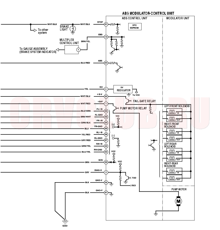
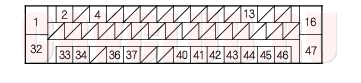
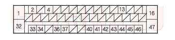
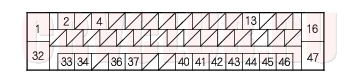
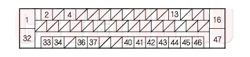
ABS Control Unit Inputs and Outputs for 47P Connector
19B-13
System Description (cont'd)19B-14
Features
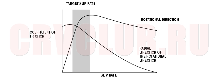
When the brake pedal is pressed during driving, the wheels can lock before the vehicle comes to a stop. In such an event, the maneuverability of the vehicle is reduced if the front wheels are locked, and the stability of the vehicle is reduced if the rear wheels are locked, creating an extremely unstable condition. The ABS precisely controls the slip rate of the wheels thereby ensuring the maneuverability and stability of the vehicle.
The ABS calculates the slip rate of the wheels based on the wheel speed, then it controls the brake fluid pressure to reach the target slip rate.Grip Force of Tire and Road Surface
19B-15
System Description (cont'd)19B-16
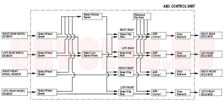
ABS Control Unit
Main Control
The ABS control unit detects the wheel speed based on the wheel sensor signal it received, then it calculates the vehicle speed based on the detected wheel speed. The control unit detects the vehicle speed during deceleration based on the rate of deceleration.
The ABS control unit calculates the slip rate of each wheel, and transmits the control signal to the modulator unit solenoid valve when the slip rate is high.
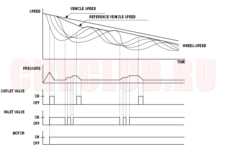
The pressure reduction control has three modes: pressure reducing, pressure retaining, and pressure intensifying.
Electronic Brake Distribution (EBD) Control
The electronic brake distribution (EBD) function helps control vehicle braking by adjusting the rear brake force before the ABS operates. Based on wheel sensor signals, the ABS control unit uses the modulator to control the rear brakes individually. When the rear wheel speed is less than the front wheel speed, the ABS control unit retains the current rear brake fluid pressure by closing the inlet valve in the modulator. As the rear wheel speed increases and approaches the front wheel speed, the control unit increases the rear brake fluid pressure by momentarily opening the inlet valve. This whole process is repeated very rapidly. While this is happening, there is kickback at the brake pedal.
During self-diagnosis. if the ABS control unit detects a problem that affects the EBD, it turns on the brake system indicator and the ABS indicator.
19B-17
Self-diagnosis Function
- The ABS control unit is equipped with a main CPU and a sub-CPU. Each CPU checks the other for problems.
- The CPUs check the circuit of the system.
- The ABS control unit turns on the ABS indicator when the unit detects a problem and the unit stops the system.
- The self-diagnosis can be classified into these two categories:
- Initial diagnosis
- Regular diagnosis
On-board Diagnosis Function
The ABS can be diagnosed with the Honda PGM Tester.
The ABS Checker cannot be used with this system. For air bleeding and checking wheel sensor signals, use the Honda PGM Tester. See the Honda PGM Tester user's manual for specific operating instructions.System Description (cont'd)19B-18
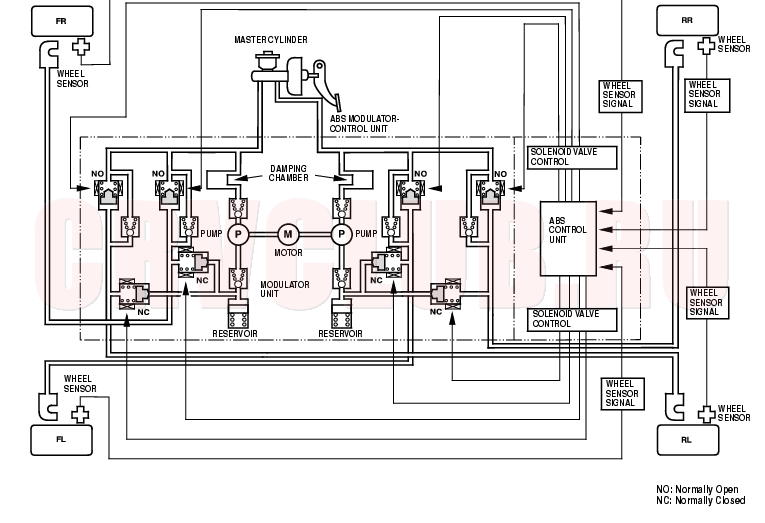
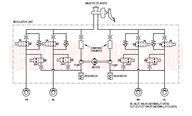
ABS Modulator
The ABS modulator consists of the inlet solenoid valve, outlet solenoid valve, reservoir, pump, pump motor, and the damping chamber. The modulator reduces the caliper fluid pressure directly. It is a circulating-type modulator because the brake fluid circulates through the caliper, reservoir, and the master cylinder. The hydraulic control has three modes: pressure intensifying, pressure retaining, and pressure reducing. The hydraulic circuit is an independent four channel-type, one channel for each wheel.
19B-19
Wheel Sensors
The wheel sensors are semiconductor type. The wheel sensors detect changes in magnetic polarity on the magnetic encoder in the wheel bearring. The ABS control unit calcurates the wheel speed based on signals received from the wheel sensor.
When the wheel speed drops sharply below the vehicle speed, the outlet valve opens momentarily to reduce the caliper fluid pressure. The pump motor starts at this time. As the wheel speed is restored, the inlet valve opens momentarily to increase the caliper fluid pressure.
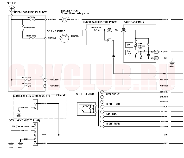
Circuit Diagram19B-20
19B-21
System Connectors19B-22
DTC Troubleshooting19B-23
DTC 11, 13, 15, 17: Wheel Sensor
(Open/Short to Body Ground/Short to Power)
- Disconnect the negative cable from the battery.
- Disconnect the ABS control unit 47P connector.
- Reconnect the battery cable.
- Start the engine.
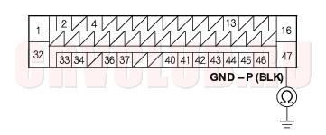
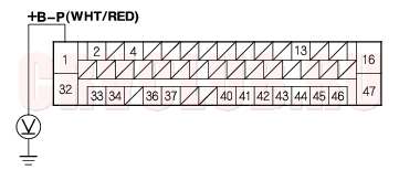
- Measure the voltage between body ground and the appropriate wheel sensor +B and GND terminals of the ABS control unit 47P connector individually (see table).
11 (Right-front) FR +B: No. 34 FR - GND: No. 33 13 (Left-front) FR +B: No. 45 FL - GND: No. 46 15 (Right-rear) RR +B: No. 43 RR - GND: No. 42 17 (Left-rear) RL +B: No. 36 RL - GND: No. 37
Is there battery voltage?
Yes : Repair short to power in the wiree between the ABS modulator-control unit and the appropriate wheel sensor.

No : Go to step 6.
- Turn the ignition switch OFF.
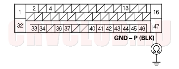
- Check for continuity between body ground and the appropriate wheel sensor +B and GND terminals of the ABS control unit 47P connector individually (see table).
11 (Right-front) FR +B: No. 34 FR - GND: No. 33 13 (Left-front) FR +B: No. 45 FL - GND: No. 46 15 (Right-rear) RR +B: No. 43 RR - GND: No. 42 17 (Left-rear) RL +B: No. 36 RL - GND: No. 37
Is there continuity?
Yes : Go to step 8.
No : Go to step 10.
DTC Troubleshooting (cont'd)19B-24
- Disconnect the wire harness 2P connector from the appropriate wheel sensor.
- Check for continuity between body ground and the appropriate wheel sensor +B and GND terminals of the ABS control unit 47P connector individually (see table).
11 (Right-front) FR +B: No. 34 FR - GND: No. 33 13 (Left-front) FR +B: No. 45 FL - GND: No. 46 15 (Right-rear) RR +B: No. 43 RR - GND: No. 42 17 (Left-rear) RL +B: No. 36 RL - GND: No. 37
Is there continuity?
Yes : Repair short to body ground in the wire between the ABS modulator-control unit and the wheel sensor.
No : Replace the wheel sensor.
- Measure the resistance between the appropriate wheel sensor +B and GND terminals of the ABS control unit 47P connector (see table), then measure the resistance between same terminals after changing positive tester prove and negative tester probe.
11 (Right-front) FR +B: No. 34 FR - GND: No. 33 13 (Left-front) FR +B: No. 45 FL - GND: No. 46 15 (Right-rear) RR +B: No. 43 RR - GND: No. 42 17 (Left-rear) RL +B: No. 36 RL - GND: No. 37
Is the resistance infinity at both sides?
Yes : Go to step 11.
No : Go to step 12.
19B-25
- Disconnect the wire harness 2P connector from the appropriate wheel sensor.
- Measure the resistance between the appropriate wheel sensor +B and GND terminals of the ABS control unit 47P connector (see table), then measure the resistance between same terminals after changing positive tester prove and negative tester probe.
11 (Right-front) FR +B: No. 34 FR - GND: No. 33 13 (Left-front) FR +B: No. 45 FL - GND: No. 46 15 (Right-rear) RR +B: No. 43 RR - GND: No. 42 17 (Left-rear) RL +B: No. 36 RL - GND: No. 37
Is the resistance infinity at both sides?
Yes : Repair open in the wire between the ABS modulator-control unit and the wheel sensor.
No : Replace the wheel sensor.
- Check for continuity between the appropriate wheel sensor +B and GND terminals of the ABS control unit 47P connector (see table), then check for continuity between same terminals after changing positive tester prove and negative tester probe.
11 (Right-front) FR +B: No. 34 FR - GND: No. 33 13 (Left-front) FR +B: No. 45 FL - GND: No. 46 15 (Right-rear) RR +B: No. 43 RR - GND: No. 42 17 (Left-rear) RL +B: No. 36 RL - GND: No. 37
Is there continuity at both sides?
Yes : Repair short in the wire between the ABS modulator-control unit and the wheel sensor.
No : Check for loose ABS control unit 47P connector. If necessary, substitute a known-good ABS modulator-control unit, and recheck.
DTC Troubleshooting (cont'd)19B-26
DTC 12, 14, 16, 18: Wheel Sensor (Electrical Noise/Intermittent Interruption)
NOTE: If the ABS indicator comes on because of electrical noise, the indicator goes off when you test-drive the vehicle at 19 mph (30 km/h).
- Check the appropriate wheel sensor and magnetic encoder (see page 19B-38) .
12 Right-front 14 Left-front 16 Right-rear 18 Left-rear
Are they OK?
Yes : Go to step 2.
No : Reinstall or replace the appropriate wheel sensor or magnetic encoder.
- Disconnect the negative cable from the battery.
- Disconnect the ABS control unit 47P connector.
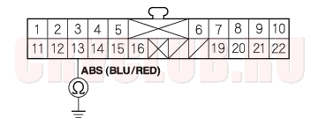
- Check for continuity between the appropriate wheel sensor GND terminal and other wheel sensor GND terminals (see table).
Is there continuity?
Yes : Repair short in the wire between the appropriate wheel sensor and the other wheel sensor.
No : Clear the DTC, and test-drive the vehicle. If the ABS indicator comes on and the same DTC is indicated, replace the ABS modulator-control unit.
19B-27
DTC 21, 22, 23, 24: Magnetic Encoder
- Clear the DTC (see step 1 on page 19B-7 ) .
- Test-drive the vehicle at 19 mph (30 km/h) or more.
Does the ABS indicator come on, and are DTCs 21, 22, 23, 24 indicated?
Yes : Go to step 3.
No : The system is OK at this time.
- Check the appropriate wheel sensor (see table) (see page 19B-38) .
21 Right-front 22 Left-front 23 Right-rear 24 Left-rear
Is the encoder OK?
Yes : Check for loose terminals in the ABS control unit 25P connector. If necessary, substitute a known-good ABS modulator-control unit, and recheck.
No : Replace the magnetic encoder.
DTC 31, 32, 33, 34, 35, 36, 37, 38: Solenoid
- Clear the DTC (see step 1 on page 19B-7 ).
- Turn the ignition switch ON (II).
- Verify the DTC.
Does the ABS indicator come on, and are DTCs 31, 32, 33, 34, 35, 36, 37, 38 indicated?
Yes : Check for loose terminals in the ABS control unit 47P connector. If necessary, substitute a known-good ABS modulator-control unit, and recheck.
No : The system is OK at this time.
DTC Troubleshooting (cont'd)19B-28
DTC 51: Motor Lock
Is the fuse OK?
Yes : Reinstall the fuse, and go to step 2.
No : Replace the fuse, and recheck.
- Disconnect the negative cable from the battery.
- Disconnect the ABS control unit 47P connector.
- Reconnect the battery cable.
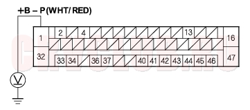
- Measure the voltage between the ABS control unit 47P connector terminal No. 1 and body ground.
Is there battery voltage?
Yes : Go to step 6.
No : Repair open in the wire between the No. 10 (30A) fuse and the ABS control unit.
Is there continuity?
Yes : Go to step 7.
No : Repair open in the wire between the ABS control unit and body ground (G202).
- Disconnect the negative cable from the battery.
- Reconnect the ABS control unit 47P connector.
- Reconnect the battery cable.
- Clear the DTC.
- Test-drive the vehicle at 6 mph (10 km/h) or more.
Does the ABS indicator come on, and is DTC 51 indicated?
Yes : Replace the ABS modulator-control unit.
No : The system is OK at this time.
19B-29
DTC 52: Motor Stuck OFF
Is the fuse OK?
Yes : Reinstall the fuse, and go to step 2.
No : Replace the fuse, and recheck.
- Disconnect the negative cable from the battery.
- Disconnect the ABS control unit 47P connector.
- Reconnect the battery cable.
- Measure the voltage between the ABS control unit 47P connector terminal No. 1 and body ground.
Is there battery voltage?
Yes : Go to step 6.
No : Repair open in the wire between the No. 10 (30A) fuse and the ABS control unit.
Is there continuity?
Yes : Check for loose terminals in the ABS control unit 47P connector. If necessary, substitute a known-good ABS modulator control unit, and recheck.
No : Repair open in the wire between the ABS control unit and body ground (G202).
DTC Troubleshooting (cont'd)19B-30
DTC 53: Motor Stuck ON
- Clear the DTC (see step 1 on page 19B-7 ).
- Test-drive the vehicle.
Does the ABS indicator come on and is DTC 53 indicated?
Yes : Replace the ABS modulator-control unit.
No : The system is OK at this time.
DTC 54: ABS Fail-safe Relay
- Clear the DTC (see step 1 on page 19B-7 ).
- Test-drive the vehicle.
Does the ABS indicator come on and is DTC 54 indicated?
Yes : Replace the ABS modulator-control unit.
No : Intermittent failure; the vehicle is OK at this time.
19B-31
DTC 61, 62: IG1 Voltage
- Clear the DTC (see step 1 on page 19B-7 ).
- Test-drive the vehicle at 6 mph (10 km/h) or more.
Does the ABS indicator come on?
Yes : Go to step 3.
No : The system is OK at this time.
Is DTC 61 or 62 indicated?
Yes : Check the charging system.
No : Perform the appropriate troubleshooting for the DTC.
DTC 81: Central Processing Unit (CPU) Diagnosis, and ROM/RAM Diagnosis
- Clear the DTC (see step 1 on page 19B-7 ).
- Test-drive the vehicle.
Does the ABS indicator come on and is DTC 81 indicated?
Yes : Replace the ABS modulator-control unit.
No : Intermittent failure; the vehicle is OK at this time.
ABS Indicator Circuit Troubleshooting19B-32
ABS indicator does not come on
Does the ABS indicator come on?
Yes : The system is OK at this time.
No : Go to step 2.
Does the brake system indicator come on?
Yes : Go to step 3.
No : Repair open in the indicator power source circuit.
Blown No. 10 (7.5A) fuse in the under-dash fuse/relay box. Open in the wire between the No. 10 (7.5A) fuse and the gauge assembly. Open circuit inside the fuse box.
- Turn the ignition switch OFF.
- Disconnect the negative cable from the battery.
- Disconnect the ABS control unit 47P connector.
- Reconnect the battery cable.
- Turn the ignition switch ON (II).
Does the ABS indicator come on?
Yes : Check for loose terminals in the ABS control unit 47P connector. If necessary, substitute a known-good ABS modulator-control unit, and recheck.
No : Go to step 8.
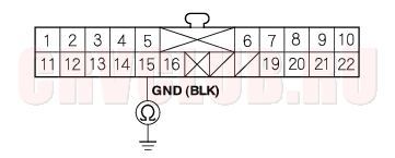
- Remove the gauge assembly (see page 22A-74) .
- Disconnect the gauge assembly connector B (22P).
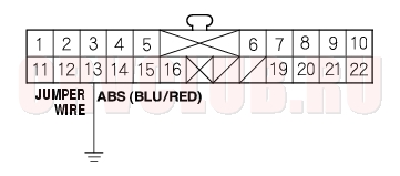
- Check for continuity between the gauge assembly connector B (22P) terminal No. 13 and body ground.
Is there continuity?
Yes : Repair short to body ground in the wire between the gauge assembly and the ABS control unit.
No : Go to step 11.
Is there continuity?
Yes : Check for loose terminals in the gauge assembly connectors. If the connector is OK, replace the gauge assembly.
No : Repair open in the wire between the gauge assembly and body ground (G502).
19B-33
ABS indicator does not go off
- Disconnect the negative cable from the battery.
- Disconnect the ABS control unit 47P connector.
- Reconnect the battery cable.
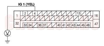
- Turn the ignition switch ON (II).
- Measure the voltage between the ABS control unit 47P connector terminal No. 4 and body ground.
Is there battery voltage?
Yes : Go to step 6.
No : Repair open in the wire between the No. 10 (7.5 A) fuse in the under-dash fuse/relay box and the ABS control unit.
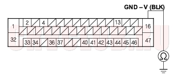
- Turn the ignition switch OFF.
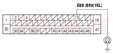
- Check for continuity between the ABS control unit 47P connector terminal No. 16 and body ground.
Is there continuity?
Yes : Go to step 8.
No : Repair open in the wire between the ABS control unit and body ground (G202).
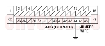
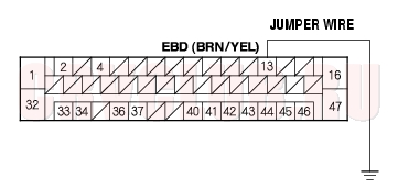
- Turn the ignition switch OFF.
- Connect the ABS control unit 47P connector terminal No. 44 and body ground with a jumper wire.
Does the ABS indicator go off?
Yes : Check for loose terminals in the ABS control unit 47P connector. If necessary, substitute a known-good ABS modulator-control unit, and recheck.
No : Go to step 10.
ABS Indicator Circuit Troubleshooting (cont'd)19B-34
- Turn the ignition switch OFF.
- Remove the jumper wire from the ABS control unit 47P connector.
- Remove the gauge assembly (see page 22A-74) .
- Turn the ignition switch ON (II).
- Connect the gauge assembly connector B (22P) terminal No. 13 and body ground with a jumper wire.
Does the ABS indicator go off?
Yes : Repair open in the wire between the gauge assembly and the ABS control unit.
No : Check for loose terminals in the gauge assembly connectors. If the connectors are OK, replace the gauge assembly.
Brake System Indicator Circuit Troubleshooting19B-34
Brake system indicator does not come on
- Disconnect the negative cable from the battery.
- Disconnect the multiplex control unit 13P connector and the ABS control unit 47P connector.
- Check for continuity between the ABS control unit 47P connector terminal No. 13 and body ground.
Is there continuity?
Yes : Repair short to body ground in the wire between the multiplex control unit and the ABS control unit.
No : Go to multiplex control system troubleshooting (see page 22A-235).
19B-35
Brake system indicator does not go off
Does the brake system indicator go off?
Yes : The system is OK at this time.
No : Go to step 3.
Is the level OK?
Yes : Go to step 4.
No : Refill the brake fluid, and recheck.
Does the ABS indicator stay on?
Yes : Read the ABS DTC (see page 19B-5), and do applicable troubleshooting for the DTC.
No : Go to step 5.
- Turn the ignition switch OFF.
- Disconnect the negative cable from the battery.
- Disconnect the ABS control unit 47P connector.
- Reconnect the battery cable.
- Connect the ABS control unit 47P connector terminal No. 13 and body ground with a jumper wire.
Does the brake system indicator go off?
Yes : Replace the ABS modulator-control unit.
No : Go to step 12.
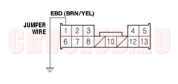
- Turn the ignition switch OFF.
- Connect the multiplex control unit 13P connector terminal No. 1 and body ground with a jumper wire.
Does the brake system indicator go off?
Yes : Repair open in the wire between the multiplex control unit and the ABS control unit.
No : Go to multiplex control system troubleshooting (see page 22A-235).
ABS Modulator-Control Unit Removal and Installation19B-36
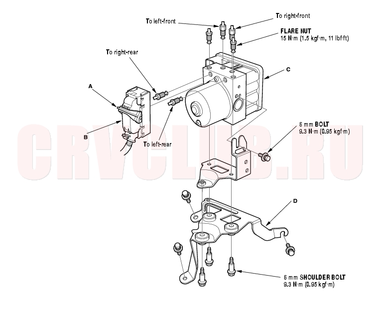
Do not spill brake fluid on the vehicle; it may damage the paint; if brake fluid gets on the paint, wash it off immediately with water. Be careful not to damage or deform the brake lines during removal and installation. To prevent the brake fluid from flowing, plug and cover the hose ends and joints with a shop towel or equivalent material. Removal
- Turn the ignition switch.
- Disconnect the negative cable from the battery.
- Pull up the lock (A) of the ABS control unit 47P connector (B), then disconnect the connector.
19B-37
- Disconnect the six brake lines.
- Remove the ABS modulator-control unit (C)/bracket (D) from the body.
- Remove the two 6 mm shoulder bolts and the 6 mm bolt from the bracket, then remove the ABS modulator-control unit from the bracket.
Installation
- Install the ABS modulator-control unit to the bracket, then tighten the two 6 mm shoulder bolts and the 6 mm bolt.
- Install the ABS modulator-control unit/bracket to the body.
- Align the connecting surface of the ABS control unit 47P connector.
- Push in the lock of the ABS control unit 47P connector, then connect the connector.
- Connect the six brake lines.
- Bleed the brake system, starting with the front wheels.
- Start the engine, and check that the ABS indicator and brake system indicator go off.
- Test-drive the vehicle, and check that the ABS indicator and brake system indicator do not come on.
Wheel Sensor Inspection19B-38
- Remove the knuckle.
- Front (see page 18-12) .
- Rear (see page 18-27) .
- Check the magnetic encoder after cleaning the encoder. If necessary, replace the encoder.
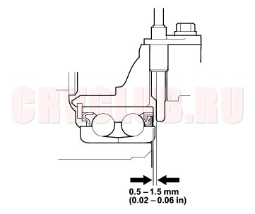
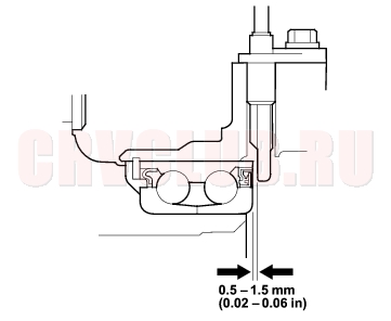
- Measure the air gap between the wheel sensor and the magnetic encoder all the way around while rotating the encoder.
Standard:
Front/Rear: 0.5 - 1.5 mm (0.02-0.06 in.)
- Install the knuckle.
- Front (see step 14 on page 18-15 ).
- Rear (see step 14 on page 18-30 ).
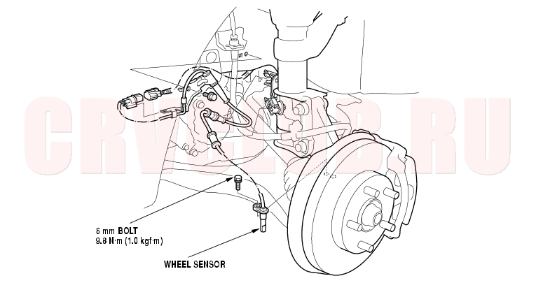
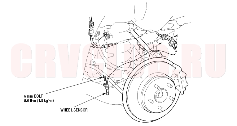
Wheel Sensor Replacement19B-39
NOTE: Install the sensors carefully to avoid twisting the wires.
|
Brakes19B-1
ABS Components19B-2 |