SRS23-14
|
Restraints23-1
SRS23-14 |
SRS23-14
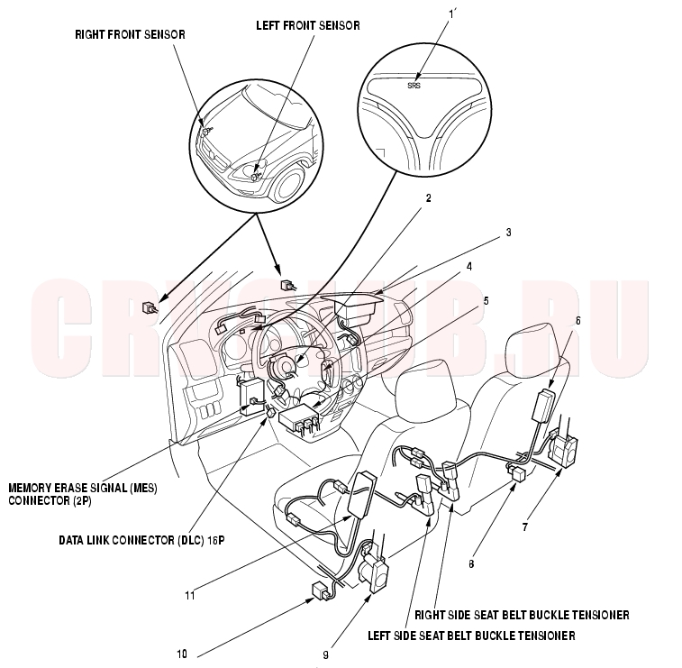
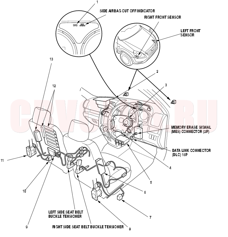
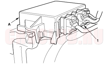
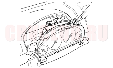
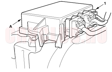
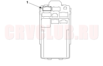
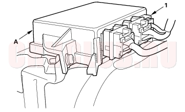
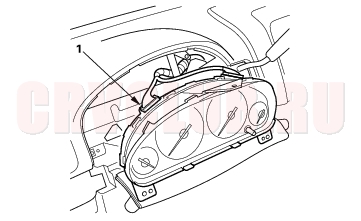
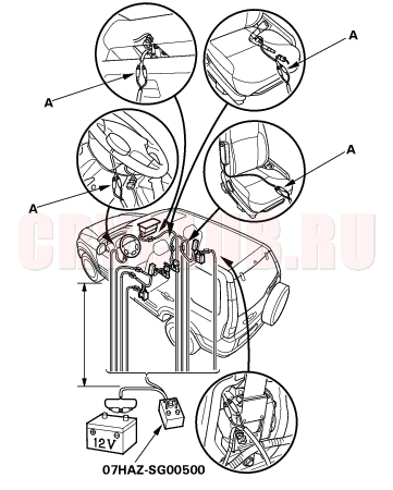
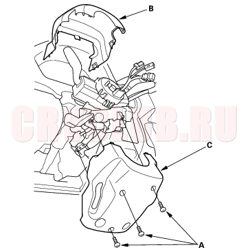
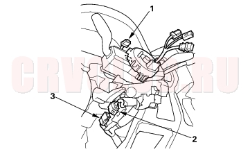
Component Location Index
LHD:
Troubleschooting, page 23-124
Replacement, page 23-4 Disposal, page 23-138 Replacement, page 23-141
Replacement, page 23-145 Replacement, page 23-136 Disposal, page 23-138
Replacement, page 23-4 Disposal, page 23-138 Replacement, page 23-135 Disposal, page 23-138
Replacement, page 23-145 Replacement, page 23-144
Replacement, page 23-137 Disposal, page 23-138 Replacement, page 23-137 Disposal, page 23-138
23-15
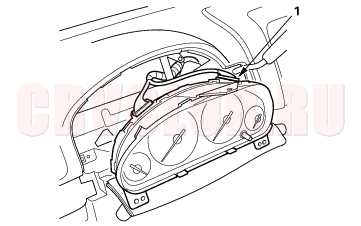
RHD
Troubleschooting, page 23-124 Replacement, page 23-4 Disposal, page 23-138 Replacement, page 23-136 Disposal, page 23-138 Initialization, page 23-30 Replacement, page 23-146 Replacement, page 23-141 Replacement, page 23-145 Replacement, page 23-135 Disposal, page 23-138 Replacement, page 23-4 Disposal, page 23-138 Replacement, page 23-144 Replacement, page 20-110 Replacement, page 23-137 Disposal, page 23-138 Replacement, page 23-137 Disposal, page 23-138 Replacement, page 23-145
Precautions and Procedures23-16
General Precautions
Please read the following precautions carefully before performing airbag system service. Observe the instructions described in this manual, or the airbags could accidentally deploy and cause damage or injuries.
Except when performing electrical inspections, always turn the ignition switch OFF, disconnect the negative cable from the battery, and wait at least 3 minutes before beginning work.
NOTE: The memory is not erased even if the ignition switch is turned OFF or the battery cables are disconnected from the battery.Use replacement parts which are manufactured to the same standards and quality as the original parts. Do not install used SRS parts from another vehicle. Use only new parts when making SRS repairs. Carefully inspect any SRS part before you install it.
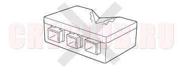
Do not install any part that shows signs of being dropped or improperly handled, such as dents, cracks or deformation.
Before removing any SRS parts (including the disconnection of connectors), always disconnect the SRS connector. Use only a digital multimeter to check the system. If it is not a Honda multimeter, make sure its output is 10 mA (0.01 A) or less when switched to the lowest value in the ohmmeter range. A tester with a higher output could cause accidental deployment and possible injury. Do not put objects on the front passenger's airbag. Steering-related Precautions
Cable Reel Alignment
Misalignment of the cable reel could cause an open in the wiring, making the SRS system and the horns inoperative. Center the cable reel whenever the following is performed (see step 6 on page 23-143 ).
Installation of the steering wheel Installation of the cable reel Installation of the steering column Other steering-related adjustment or installation Do not disassemble the cable reel. Do not apply grease to the cable reel. If the cable reel shows any signs of damage, replace it with a new one. For example, it does not rotate smoothly. 23-17
Airbag Handling and Storage
Do not disassemble an airbag. It has no serviceable parts. Once an airbag has been deployed, it cannot be repaired or reused.
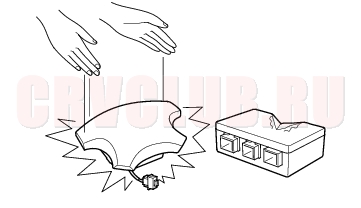
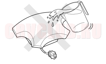
For temporary storage of airbag during service, observe the following precautions.
Store the removed airbag with the pad surface up. Never put anything on the airbag.
To prevent damage to the airbag assembly, keep free from any oil, grease, detergent, or water.
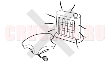
Store the removed airbag on a secure, flat surface away from any high heat source (exceeding 200°F/93°C).
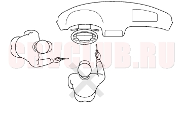
Never perform electrical inspections to the airbags, such as measuring resistance. Do not position yourself in front of the airbag assembly during removal, inspection, or replacement.
Refer to the scrapping procedures for disposal of a damaged airbag. Precautions and Procedures (cont'd)23-18
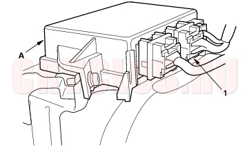
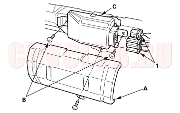
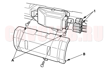
SRS Unit, Front Sensors and Side Impact Sensors
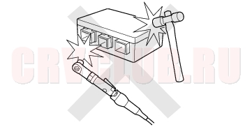
Be careful not to bump or impact the SRS unit, front sensors, or the side impact sensors whenever the ignition switch is ON (II), or for at least 3 minutes after the ignition switch is turned OFF. During installation or replacement, be careful not to bump (by impact wrench, hammer, etc.) the area around the SRS unit, front sensors, and the side impact sensor. The airbags could accidentally deploy and cause damage or injury.
After a collision in which any airbags or seat belt tensioners were deployed, replace the SRS unit, front sensors, and other related components (see page 23-134) . After a collision in which a side airbag was deployed, replace the side impact sensor on the deployed side and the SRS unit. After a collision in which the airbags or the side airbags did not deploy, inspect for any damage or any deformation on the SRS unit, front sensors, and the side impact sensors. If there is any damage, replace the SRS unit and/or the side impact sensors.
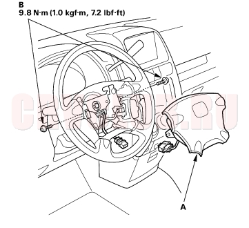
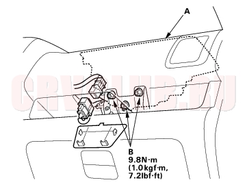
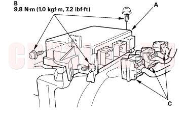
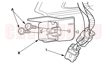
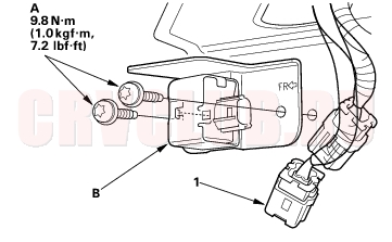
Do not disassemble the SRS unit or the side impact sensors. Turn the ignition switch OFF, disconnect the battery negative cable, and wait at least 3 minutes before beginning installation or replacement of the SRS unit, or disconnecting the connectors from the SRS unit. Be sure the SRS unit and side impact sensors are installed securely, with the mounting bolts torqued to 9.8 N·m (1.0 kgf·m, 7.2 lbf·ft) Do not spill water or oil on the SRS unit or the side impact sensors, and keep them away from dust. Store the SRS unit and the side impact sensors in a cool (less than 104°F/40°C) and dry (less than 80 % relative humidity, no moisture) area. 23-19
Wiring Precautions
Some of the SRS wiring can be identified by special yellow outer covering, and the SRS connectors can be identified by their yellow color.
Observe the instructions described in this section.
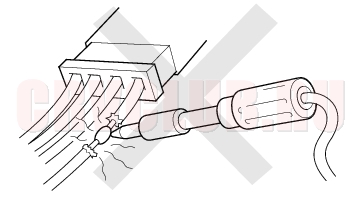
Never attempt to modify, splice, or repair SRS wiring.
If there is an open or damage in SRS wiring, replace the harness.
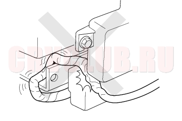
Be sure to install the harness wires so they do not get pinched or interfere with other parts.
Make sure all SRS ground locations are clean, and grounds are securely fastened for optimum metal-to-metal contact. Poor grounding can cause intermittent problems that are difficult to diagnose. Precautions for Electrical Inspections
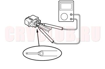
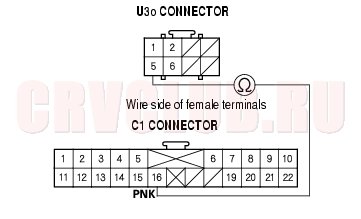
When using electrical test equipment, insert the probe of the tester into the wire side of the connector. Do not insert the probe of the tester into the terminal side of the connector, and do not tamper with the connector.
Use a U-shaped probe. Do not insert the probe forcibly.
Use specified service connectors in troubleshooting.
Using improper tools could cause an error in inspection due to poor metal-to-metal contact.Precautions and Procedures (cont'd)23-20
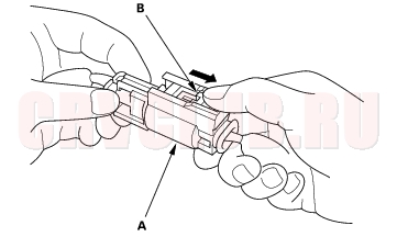
Spring-loaded Lock Connector
Some SRS system connectors have a spring-loaded lock.
Front Airbag Connectors:
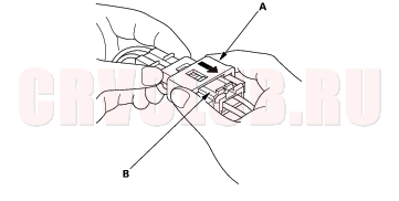
Disconnecting
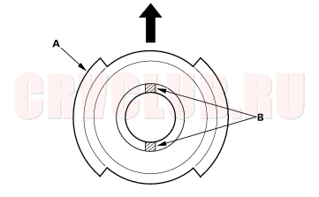
To release the lock, pull the spring-loaded sleeve (A) toward the stop (B) while holding the opposite half of the connector. Then pull the connector halves apart. Be sure to pull on the sleeve and not on the connector.
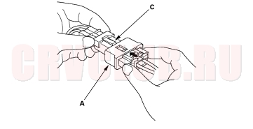
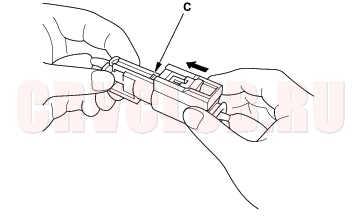
Connecting
- To reconnect, hold the pawl-side connector, and press on the back of the sleeve-side connector in the direction shown. As the two connector halves are pressed together, the sleeve (A) is pushed back by the pawl (C). Do not touch the sleeve.
- When the connector halves are completely connected, the pawl is released, and the spring-loaded sleeve locks the connector.
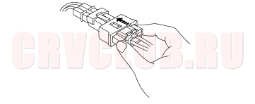
Side Airbag Connector:
Disconnecting
To release the lock, pull the spring-loaded sleeve (A) and the slider (B) while holding the opposite half of the connector. Then pull the connector halves apart. Be sure to pull on the sleeve and not on the connector half.
Connecting
Hold both connector halves, and press them firmly together until the projection (C) of the sleeve-side connector clicks.
23-21
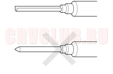
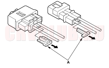
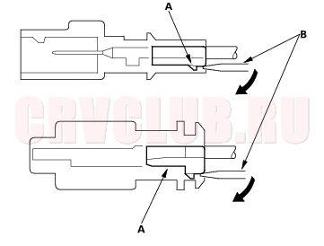
Backprobing Spring-loaded Lock Connectors
When checking voltage or resistance on this type of connector the first time, you must remove the retainer to insert the tester probe from the wire side.
NOTE: It is not necessary to reinstall the removed retainer; the terminals will stay locked in the connector housing.
To remove the retainer (A), insert a flat-tip screwdriver (B) between the connector body and the retainer, then carefully pry out the retainer. Take care not to break the connector.
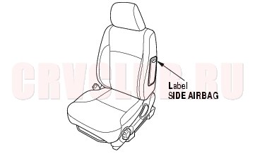
Seats with Side Airbags
Seats with side airbags have a ''SIDE AIRBAG'' label on the seat-back. Because the component parts (seat-back cover, cushion, etc.) of seats with and without airbags are different, make sure you install only the correct replacement parts.
When cleaning, do not saturate the seat with liquid, and do not spray steam on the seat. Do not repair a torn or frayed seat-back cover. Replace the seat-back cover. After a collision in which the side airbag was deployed, replace the side airbag with new parts. If the seat-back cushion is split, it must be replaced. If the seat-back frame is deformed, it must be replaced. Never put aftermarket accessories on the seat (covers, pads, seat heaters, lights, etc.). Precautions and Procedures (cont'd)23-22
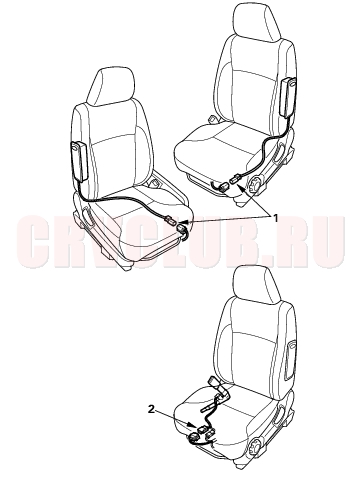
Disconnecting the Airbag Connectors, Side Airbag Connectors, Seat Belt Buckle Tensioner Connectors and Seat Belt Tensioner Connectors
Before removing a front airbag, side airbag or other SRS related devices (the SRS unit, the cable reel, the side impact sensors, the seat belt buckle tensioners and the seat belt tensioner connector), disconnecting connectors from related devices, or removing the dashboard or the steering column, disconnect the airbag connectors or the side airbag connectors to prevent accidental deployment.
Turn the ignition switch OFF and disconnect the negative cable from the battery, and wait at least 3 minutes before beginning the following procedures.
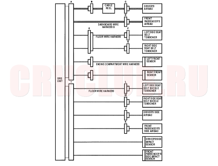
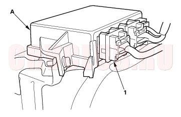
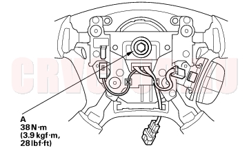
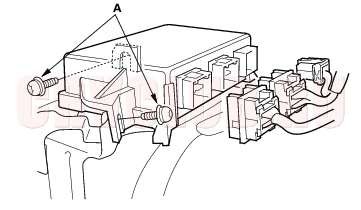
Before disconnecting the dashboard wire harness B 18P connector (A) from the SRS unit, disconnect the driver's airbag 2P connector (C), the front passenger's airbag 2P connector (D), the left side seat belt tensioner 2P connector (F), and the right side seat belt tensioner 2P connector (G). Before disconnecting the floor wire harness 18P connector (I) from the SRS unit, disconnect both side airbag 2P connectors (J, K) and both seat belt buckle tensioner 4P connector (L, M). Before disconnecting the cable reel 4P connector (B), disconnect the driver's airbag 2P connector (C). Before disconnecting the floor wire harness 4P connector (E), disconnect both seat belt tensioner 2P connectors (F, G).
23-23
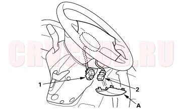
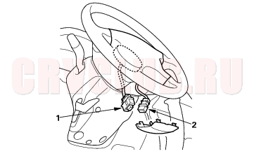
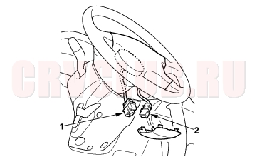
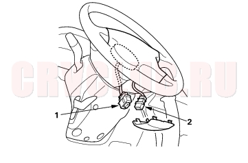
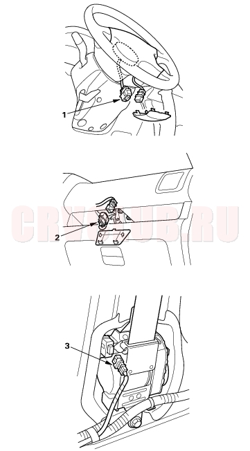
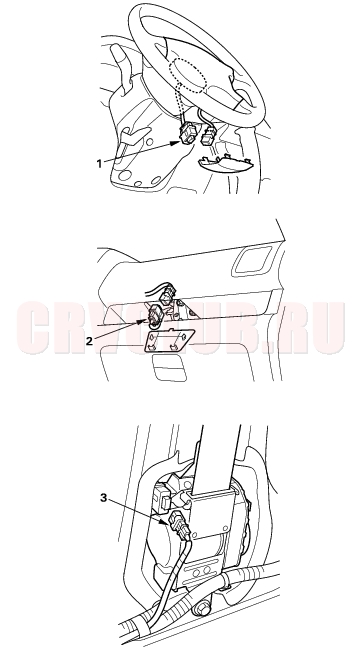
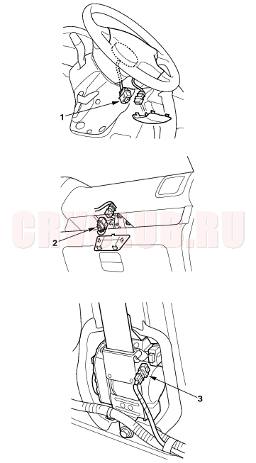
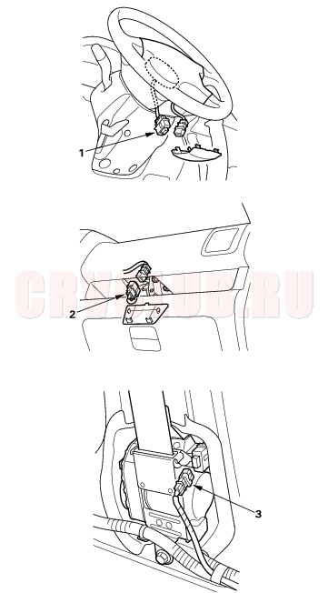
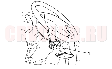
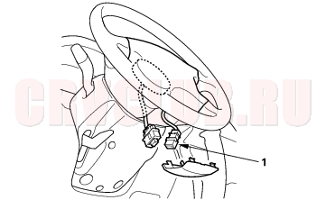
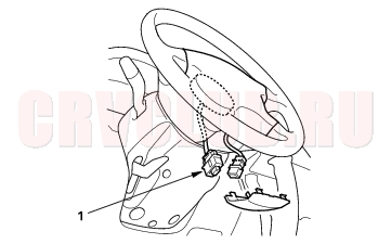
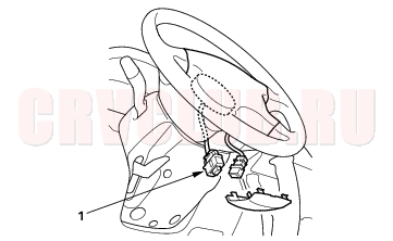
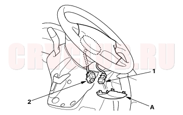
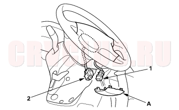
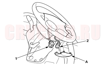
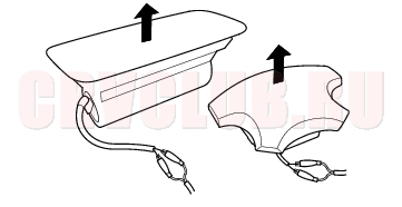
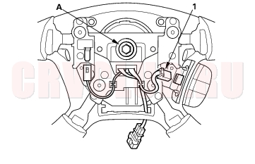
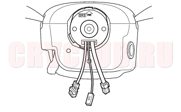
Driver's Airbag
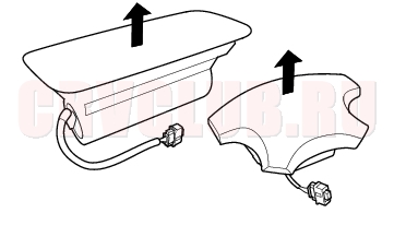
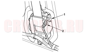
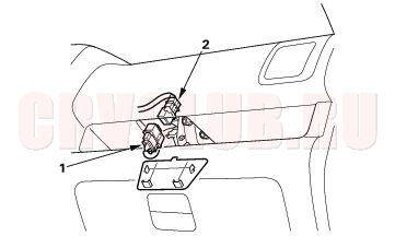
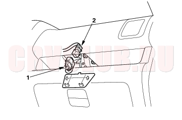
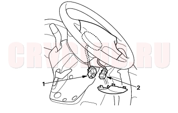
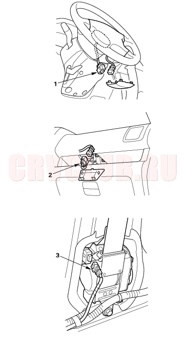
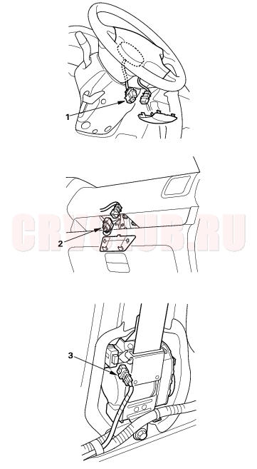
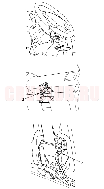
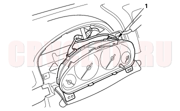
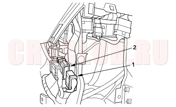
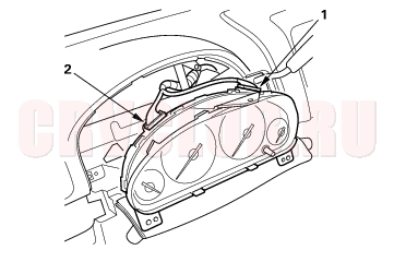
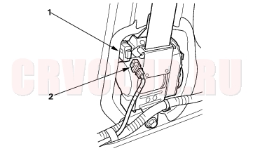
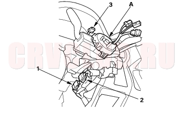
- Remove the access panel (A) from the steering wheel, then disconnect the driver's airbag 2P connector (1) from the cable reel 2P connector (2).
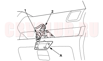
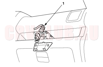
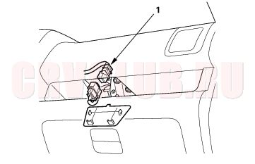
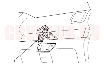
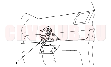
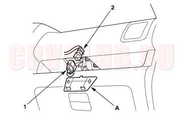
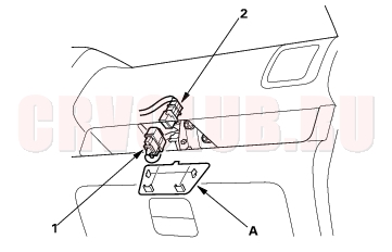
Front Passenger's Airbag
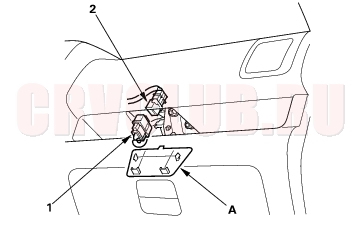
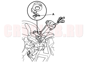
- Remove the access panel (A), then disconnect the front passenger's airbag 2P connector (1) from the dashboard wire harness B 2P connector (2).
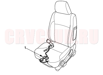
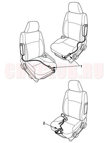
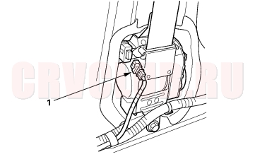
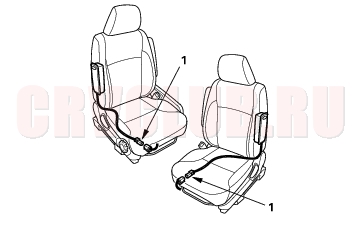
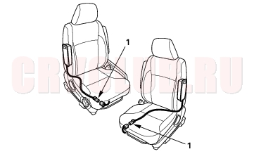
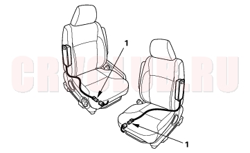
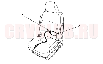
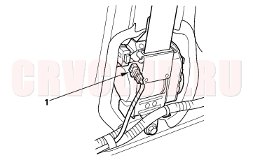
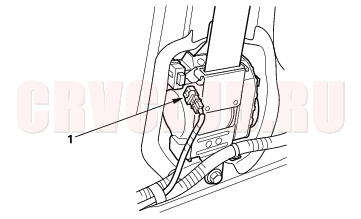
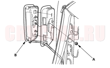
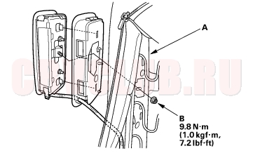
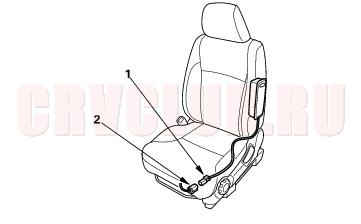
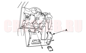
Side Airbag
Precautions and Procedures (cont'd)23-24
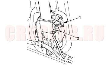
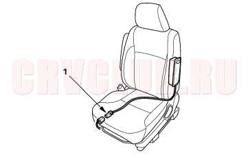
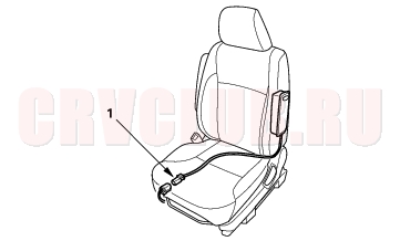
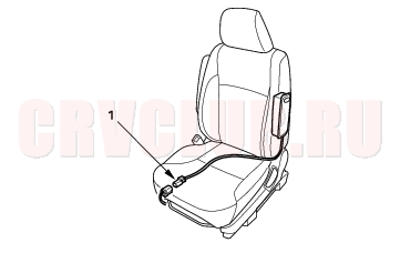
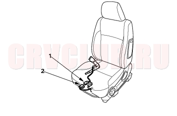
Seat Belt Tensioner
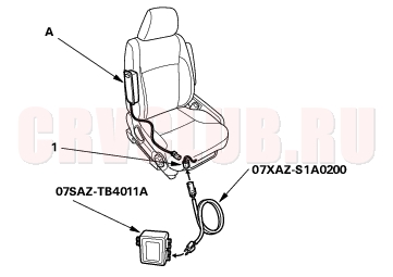
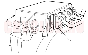
Seat Belt Buckle Tensioner
General Troubleshooting Information23-25
DTC (Diagnostic Trouble Codes)
The self-diagnostic function of the SRS system allows it to locate the causes of system problems and then store this information in memory. For easier troubleshooting, this data can be retrieved via a data link circuit.
When you turn the ignition switch ON (II), the SRS indicator will come on. If it goes off after 6 seconds, the system is normal. If there is an abnormality, the system locates and defines the problem, stores this information in memory, and turns the SRS indicator on. The data will remain in the memory even when the ignition switch is turned off or if the battery is disconnected. When you connect the Honda PGM Tester to the 16P data link connector (DLC) to short the SCS terminal, and turn the ignition switch ON (II), the SRS indicator will indicate the diagnostic trouble code (DTC) by the number of blinks. After reading and recording the DTC, proceed with the troubleshooting procedure for this code. Precautions
Use only a digital multimeter to check the system. If it's not a Honda multimeter, make sure it's output is 10 mA (0.01A) or less when switched to the smallest value in the ohmmeter range. A tester with a higher output could damage the airbag circuit or cause accidental airbag deployment and possible injury. Whenever the ignition switch is ON (II), or has been turned OFF for less than 3 minutes, be careful not to bump the SRS unit; the airbags could accidentally deploy and cause damage or injuries. Before you remove the SRS main harness, disconnect the driver's airbag connector, the front passenger's airbag connector, both side airbag connectors, both seat belt buckle tensioner connectors, and both seat belt tensioner connectors. Make sure the battery is sufficiently charged. If the battery is dead or low, measuring values won't be correct. Do not touch a tester probe to the terminals in the SRS unit or harness connectors, and do not connect the terminals with a jumper wire. Use only the backprobe set and the Honda PGM Tester. Backprobe spring-loaded lock type connectors correctly. Reading the DTC
When the SRS indicator is on, read the DTC using either of the following methods:
PGM Tester ''SRS'' Menu Method
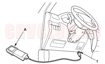
Connect the Honda PGM Tester (A) to the 16P Data Link Connector (DLC)(1), and follow the Tester's prompts in the
''SRS'' menu. If the Tester indicates no DTC, DTC 3-6 to 3-10, DTC 4-6 to 4-10, DTC 9-1, or DTC 9-2, double-check by selecting ''SCS'' on the display, and watching the SRS indicator.
General Troubleshooting Information (cont'd)23-26
''SCS'' Menu Method (retrieving the flash codes):
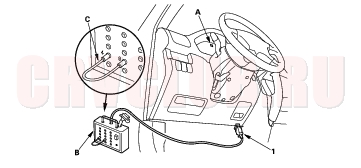
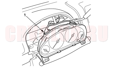
The SRS indicator (A) indicates the DTC by the number of blinks when the DTC pin box (B) is connected to the Data Link Connector (DLC)16P (1).
- Make sure the ignition switch is OFF, and wait for 10 seconds. Then connect the DLC pin box (A) to the Data Link Connector (DLC) 16P. If you don't wait 10 seconds, the SRS unit won't be completely reset or output DTCs.
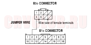
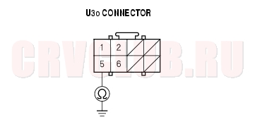
- Connect the DLC pin box terminals No. 4 and No. 9 with a jumper wire (C), and push the operation switch.
- Turn the ignition switch ON (II). The SRS indicator comes on for about 6 seconds, and then goes off. Then it will indicate the DTC.
- Read the DTC.
- Turn the ignition switch OFF, and wait for 10 seconds. Then disconnect the DLC pin box from the Data Link Connector (DLC) 16P.
- Proceed with the troubleshooting procedure for this DTC.
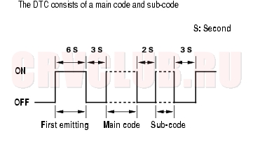
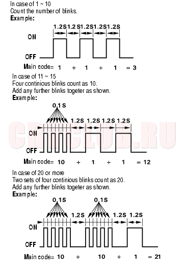
Patterns of DTC Indications:
Reading the main code:
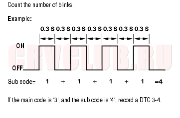
Reading the sub code:
23-27
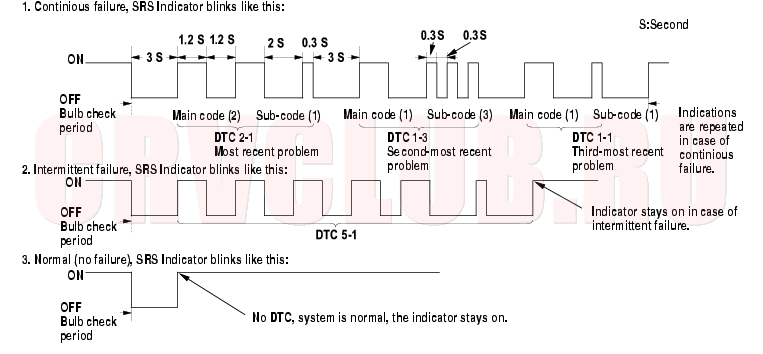
Including the most recent problem, up to three different DTCs can be indicated (see example 1 below). In case of a continuous failure, the DTC will be indicated repeatedly (see example 1 below). In case of an intermittent failure, the SRS indicator will indicate the DTCs one time, then it will stay on (see example 2 below). If both a continuous and an intermittent failure occur, both DTCs will be indicated as continuous failures. When the system is normal (no DTCs), the SRS indicator will stay on (see example 3). If the SRS indicator comes on continuously without a DTC, there may be a problem with the system. If the SRS indicator does not come on as indicated above, always check for an open or a short to ground in the SCS circuit before troubleshooting the system. Example of DTC Indications:
General Troubleshooting Information (cont'd)23-28
Reading the SRS Indicator Method (with service check connector (2P) models):
The SRS indicator indicates the DTC by the number of blinks when the SCS short connector is connected to the service check connector (2P).
- Make sure the ignition switch is OFF, and wait for 10 seconds. Then connect the SCS short connector (A) to the service check connector (2P) (B). If you don't wait 10 seconds, the SRS unit won't be completely reset or output DTCs.
- Turn the ignition switch ON (II). The SRS indicator comes on for about 6 seconds, and then goes off. Then it will indicate the DTC.
- Read the DTC.
- Turn the ignition switch OFF, and wait for 10 seconds. Then disconnect the SCS short connector from the service check connector (2P).
23-29
Erasing the DTC Memory
Special Tools Required
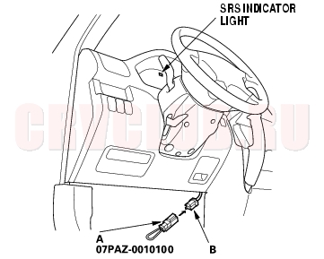
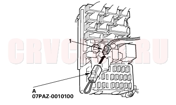
SCS short connector 07PAZ-0010100
To erase the DTC(s) from the SRS unit, use a Honda PGM Tester (see the Honda PGM Tester SRS vehicle System Supplement) or the following procedure.
- Make sure the ignition switch is OFF.
- Connect the SCS short connector (A) to the MES connector (2P) (1). Do not use a jumper wire.
- Turn the ignition switch ON (II).
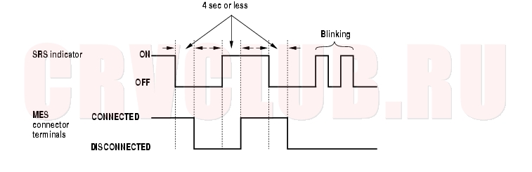
- The SRS indicator will come on for about 6 seconds, and then go off. Remove the SCS short connector from the MES connector (2P) within 4 seconds after the indicator goes off.
- The SRS indicator will come on again. Reconnect the SCS short connector to the MES connector (2P) within 4 seconds after the indicator comes on.
- When the SRS indicator goes off, remove the SCS short connector from the MES connector (2P) within 4 seconds.
- The SRS indicator will blink two times indicating that the memory has been erased.
- Turn the ignition switch OFF, and wait for 10 seconds.
- Turn the ignition switch ON (II) again. The SRS is OK if the SRS indicator comes on for 6 seconds and then goes off.
Troubleshooting Intermittent Failures
If there was a malfunction, but it doesn't recur, it will be stored in the memory as an intermittent failure, and the SRS indicator will come on.
After checking the DTC, troubleshoot as follows:
- Read the DTC (see "Reading the DTC" ).
- Erase the DTC memory (see "Erasing the DTC Memory" ).
- With the shift lever in Park or neutral, start the engine, and let it idle.
- The SRS indicator will come on for about 6 seconds and then go off.
- Shake the wire harness and the connectors, take a test drive (quick acceleration, quick braking, cornering), turn the steering wheel fully left and right, and hold it there for 5 to 10 seconds. If the problem recurs, the SRS indicator will come on.
- If you can't duplicate the intermittent failure, the system is OK at this time.
General Troubleshooting Information (cont'd)23-30
Initializing the OPDS (Occupant Position Detection System) Unit
Special Tools Required
SCS short connector 07PAZ-0010100
When a seat-back cover, seat-back cushion, and/or OPDS unit is replaced, initialize the OPDS by following the procedure below.
NOTE: Make sure the passenger's seat is dry. Set the seat-back in the normal position, and make sure there is nothing on the front passenger's seat.
- Make sure the ignition switch is OFF.
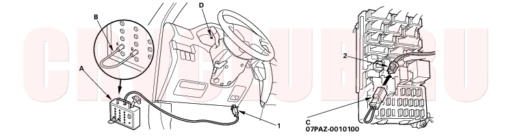
- Connect a DLC pin box (A) to the DLC (16P) (1), and connect the DLC pin box terminals No.4 and No.9 with a jumper wire (B), and push the operation switch.
- Connect the SCS short connector (C) to the MES connector (2P) (2). Do not use a jumper wire.
- Turn the ignition switch ON (II).
- The SRS indicator (D) comes on for about 6 seconds and goes off. Remove the SCS short connector from the MES connector within 4 seconds after the SRS indicator went off.
- The SRS indicator comes on again. Reconnect the SCS short connector to the MES connector within 4 seconds after the SRS indicator comes on.
- The SRS indicator goes off. Remove the SCS short connector from the MES connector within 4 seconds.
- Watch the SRS indicator.
- If the indicator blinks two times and then stays on, the OPDS is initialized, but the DTCs need to be erased. Go to step 9, then erase the DTCs.
- If the indicator blinks two times and then goes off, the OPDS unit is initialized. Go to step 9.
- If the indicator stays on without first blinking, the OPDS is not initialized. Read the DTC, and go to the appropriate page in the DTC Troubleshooting Index.
- Turn the ignition switch off, and disconnect the DLC pin box from the DLC (16P).
DTC Troubleshooting Index23-31
Without Side Airbag and Seat belt buckle tensioner Model(DENSO)
Open in driver's airbag inflator (see page 23-45) Increased resistance in driver's airbag inflator (see page 23-45) Short to another wire or decreased resistance in driver's airbag inflator (see page 23-48) Short to power in driver's airbag inflator (see page 23-50) Short to ground in driver's airbag inflator (see page 23-52) Open in front passenger's airbag inflator (see page 23-54) Increased resistance in front passenger's airbag inflator (see page 23-54) Short to another wire or decreased resistance in front passenger's airbag inflator (see page 23-55) Short to power in front passenger's airbag inflator (see page 23-57) Short to ground in front passenger's airbag inflator (see page 23-58) Open in left side seat belt tensioner (see page 23-60) Increased resistance in left side seat belt tensioner (see page 23-60) Short to another wire or decreased resistance in left side seat belt tensioner (see page 23-62) Short to power in left side seat belt tensioner (see page 23-64) Short to ground in left side seat belt tensioner (see page 23-66) Open in right side seat belt tensioner (see page 23-74) Increased resistance in right side seat belt tensioner (see page 23-74) Short to another wire or decreased resistance in right side seat belt tensioner (see page 23-76) Short to power in right side seat belt tensioner (see page 23-78) Short to ground in right side seat belt tensioner (see page 23-80) 5-1 Internal failure of SRS unit NOTE: Before troubleshooting DTCs 5-1 through 8-6, check battery/system voltage. If the voltage is low, repair the charging system before troubleshooting the SRS. (see page 23-88) Internal failure of the SRS unit. If intermittent, could mean internal failure of the unit or a faulty indicator circuit. Refer to Troubleshooting Intermittent Failures (see page 23-29) . (see page 23-88) Internal failure of the SRS unit. If intermittent, could mean internal failure of the power supply (VB line). Refer to Troubleshooting Intermittent Failures (see page 23-29) . Faulty left front sensor (see page 23-90) Faulty right front sensor (see page 23-93)
DTC Troubleshooting Index (cont'd)23-32
With Seat belt buckle tensioner, without Side Airbag Model (DENSO)
Open in driver's airbag inflator (see page 23-45) Increased resistance in driver's airbag inflator (see page 23-45) Short to another wire or decreased resistance in driver's airbag inflator (see page 23-48) Short to power in driver's airbag inflator (see page 23-50) Short to ground in driver's airbag inflator (see page 23-52) Open in front passenger's airbag inflator (see page 23-54) Increased resistance in front passenger's airbag inflator (see page 23-54) Short to another wire or decreased resistance in front passenger's airbag inflator (see page 23-55) Short to power in front passenger's airbag inflator (see page 23-57) Short to ground in front passenger's airbag inflator (see page 23-58) Open in left side seat belt tensioner (see page 23-60) Increased resistance in left side seat belt tensioner (see page 23-60) Short to another wire or decreased resistance in left side seat belt tensioner (see page 23-62) Short to power in left side seat belt tensioner (see page 23-64) Short to ground in left side seat belt tensioner (see page 23-66) Open in left side seat belt buckle tensioner (see page 23-68) Increased resistance in left side seat belt buckle tensioner (see page 23-68) Short to another wire or decreased resistance in left side seat belt buckle tensioner (see page 23-69) Short to power in left side seat belt buckle tensioner (see page 23-71) Short to ground in left side seat belt buckle tensioner (see page 23-72) Open in right side seat belt tensioner (see page 23-74) Increased resistance in right side seat belt tensioner (see page 23-74) Short to another wire or decreased resistance in right side seat belt tensioner (see page 23-76) Short to power in right side seat belt tensioner (see page 23-78) Short to ground in right side seat belt tensioner (see page 23-80) Open in right side seat belt buckle tensioner (see page 23-82) Increased resistance in right side seat belt buckle tensioner (see page 23-82) Short to another wire or decreased resistance in right side seat belt buckle tensioner (see page 23-83) Short to power in right side seat belt buckle tensioner (see page 23-85) Short to ground in right side seat belt buckle tensioner (see page 23-86)
23-33
5-1 Internal failure of SRS unit NOTE: Before troubleshooting DTCs 5-1 through 8-6, check battery/system voltage. If the voltage is low, repair the charging system before troubleshooting the SRS. (see page 23-88) 5-2 5-4 6-4 7-1 7-2 7-3 8-1 8-2 8-3 8-4 8-5 8-6 9-1 Internal failure of the SRS unit. If intermittent, could mean internal failure of the unit or a faulty indicator circuit. Refer to Troubleshooting Intermittent Failures (see page 23-29) . (see page 23-88) 9-2 Internal failure of the SRS unit. If intermittent, could mean internal failure of the power supply (VB line). Refer to Troubleshooting Intermittent Failures (see page 23-29) . 9-6 Faulty left front sensor (see page 23-90) 9-7 Faulty right front sensor (see page 23-93)
DTC Troubleshooting Index (cont'd)23-34
With Seat belt buckle tensioner and Side Airbag, without OPDS Unit Model (KEIHIN, SIEMENS)
Open or increased resistance in driver's airbag inflator (see page 23-45) 1-3 Short to another wire or decreased resistance in driver's airbag inflator (see page 23-48) 1-4 Short to power in driver's airbag inflator (see page 23-50) 1-5 Short to ground in driver's airbag inflator (see page 23-52) 2-1 Open or increased resistance in front passenger's airbag inflator (see page 23-54) 2-3 Short to another wire or decreased resistance in front passenger's airbag inflator (see page 23-55) 2-4 Short to power in front passenger's airbag inflator (see page 23-57) 2-5 Short to ground in front passenger's airbag inflator (see page 23-58) 3-1 Open or increased resistance in left side seat belt tensioner (see page 23-60) 3-3 Short to another wire or decreased resistance in left side seat belt tensioner (see page 23-62) 3-4 Short to power in left side seat belt tensioner (see page 23-64) 3-5 Short to ground in left side seat belt tensioner (see page 23-66) 21-1 Open or increased resistance in left side seat belt buckle tensioner (see page 23-68) 21-3 Short to another wire or decreased resistance in left side seat belt buckle tensioner (see page 23-69) 21-4 Short to power in left side seat belt buckle tensioner (see page 23-71) 21-5 Short to ground in left side seat belt buckle tensioner (see page 23-72) 4-1 Open or increased resistance in right side seat belt tensioner (see page 23-74) 4-3 Short to another wire or decreased resistance in right side seat belt tensioner (see page 23-76) 4-4 Short to power in right side seat belt tensioner (see page 23-78) 4-5 Short to ground in right side seat belt tensioner (see page 23-80) 22-1 Open or increased resistance in right side seat belt buckle tensioner (see page 23-82) 22-3 Short to another wire or decreased resistance in right side seat belt buckle tensioner (see page 23-83) 22-4 Short to power in right side seat belt buckle tensioner (see page 23-85) 22-5 Short to ground in right side seat belt buckle tensioner (see page 23-86) 5-1 Internal failure of SRS unit NOTE: Before troubleshooting DTCs 5-1 through 8-6, check battery/system voltage. If the voltage is low, repair the charging system before troubleshooting the SRS. (see page 23-88) 5-2 5-4 5-8 6-3 6-4 6-7 6-8 7-1 7-2 7-3 8-1 8-2 8-3 8-4 8-5 8-6
23-35
9-1 Internal failure of the SRS unit. If intermittent, could mean internal failure of the unit or a faulty indicator circuit. Refer to Troubleshooting Intermittent Failures (see page 23-29) . (see page 23-88) 9-2 Internal failure of the SRS unit. If intermittent, could mean internal failure of the power supply (VB line). Refer to Troubleshooting Intermittent Failures (see page 23-29) . 9-6 Faulty left front sensor (see page 23-90) 9-7 Faulty right front sensor (see page 23-93) 10-1 Seat belt tensioners (and airbag(s)) deployed (see page 23-88) 10-2 Left side airbag deployed 10-3 Seat belt tensioners (and airbag(s)) and left side airbag deployed 10-4 Right side airbag deployed 10-5 Seat belt tensioners (and airbag(s)) and front right side airbag deployed 10-6 Side airbags deployed 10-7 Seat belt tensioners (and airbag(s)) and side airbags deployed 11-1 Open or increased resistance in left side airbag inflator (see page 23-102) 11-3 Short to another wire or decreased resistance in left side airbag inflator (see page 23-103) 11-4 Short to power in left side airbag inflator (see page 23-105) 11-5 Short to ground in left side airbag inflator (see page 23-106) 12-1 Open or increased resistance in right side airbag inflator (see page 23-96) 12-3 Short to another wire or decreased resistance in right side airbag inflator (see page 23-97) 12-4 Short to power in right side airbag inflator (see page 23-99) 12-5 Short to ground in right side airbag inflator (see page 23-100) 13-1 Internal failure of the left side impact sensor (see page 23-89) 13-2 13-3 No signal from the left side impact sensor (see page 23-111) 13-4 Faulty power supply to the left side impact sensor (see page 23-112) 14-1 Internal failure of the right side impact sensor (see page 23-89) 14-2 14-3 No signal from the right side impact sensor (see page 23-108) 14-4 Faulty power supply to the right side impact sensor (see page 23-109)
DTC Troubleshooting Index (cont'd)23-36
Side Airbag with OPDS Unit Model (KEIHIN)
1-1 Open or increased resistance in driver's airbag inflator (see page 23-45) 1-3 Short to another wire or decreased resistance in driver's airbag inflator (see page 23-48) 1-4 Short to power in driver's airbag inflator (see page 23-50) 1-5 Short to ground in driver's airbag inflator (see page 23-52) 2-1 Open or increased resistance in front passenger's airbag inflator (see page 23-54) 2-3 Short to another wire or decreased resistance in front passenger's airbag inflator (see page 23-55) 2-4 Short to power in front passenger's airbag inflator (see page 23-57) 2-5 Short to ground in front passenger's airbag inflator (see page 23-58) 3-1 Open or increased resistance in left side seat belt tensioner (see page 23-60) 3-3 Short to another wire or decreased resistance in left side seat belt tensioner (see page 23-62) 3-4 Short to power in left side seat belt tensioner (see page 23-64) 3-5 Short to ground in left side seat belt tensioner (see page 23-66) 4-1 Open or increased resistance in right side seat belt tensioner (see page 23-74) 4-3 Short to another wire or decreased resistance in right side seat belt tensioner (see page 23-76) 4-4 Short to power in right side seat belt tensioner (see page 23-78) 4-5 Short to ground in right side seat belt tensioner (see page 23-80) 5-1 Internal failure of SRS unit
NOTE: Before troubleshooting DTCs 5-1 through 8-6, check battery/system voltage. If the voltage is low, repair the charging system before troubleshooting the SRS.(see page 23-88) 5-2 5-4 5-8 6-3 6-4 6-7 6-8 7-1 7-2 7-3 8-1 8-2 8-3 8-4 8-5 8-6
23-37
9-1 Internal failure of the SRS unit. If intermittent, could mean internal failure of the unit or a faulty indicator circuit. Refer to Troubleshooting Intermittent Failures (see page 23-29) . (see page 23-88) 9-2 Internal failure of the SRS unit. If intermittent, could mean internal failure of the power supply (VB line). Refer to Troubleshooting Intermittent Failures (see page 23-29) . 9-6 Faulty left front sensor (see page 23-90) 9-7 Faulty right front sensor (see page 23-93) 10-1 Seat belt tensioners (and airbag(s)) deployed (see page 23-88) 10-2 Driver's side airbag deployed 10-3 Seat belt tensioners (and airbag(s)) and driver's side airbag deployed 10-4 Front passenger's side airbag deployed 10-5 Seat belt tensioners (and airbag(s)) and front passenger's side airbag deployed 10-6 Driver's and front passenger's side airbags deployed 10-7 Seat belt tensioners (and airbag(s)) and driver's and front passenger's side airbags deployed 11-1 Open or increased resistance in driver's side airbag inflator (see page 23-96) 11-3 Short to another wire or decreased resistance in driver's side airbag inflator (see page 23-97) 11-4 Short to power in driver's side airbag inflator (see page 23-99) 11-5 Short to ground in driver's side airbag inflator (see page 23-100) 12-1 Open or increased resistance in front passenger's side airbag inflator (see page 23-102) 12-3 Short to another wire or decreased resistance in front passenger's side airbag inflator (see page 23-103) 12-4 Short to power in front passenger's side airbag inflator (see page 23-105) 12-5 Short to ground in front passenger's side airbag inflator (see page 23-106) 13-1 Internal failure of the driver's side impact sensor (see page 23-89) 13-2 13-3 No signal from the driver's side impact sensor (see page 23-108) 13-4 Faulty power supply to the driver's side impact sensor (see page 23-109) 14-1 Internal failure of the front passenger's side impact sensor (see page 23-89) 14-2 14-3 No signal from the front passenger's side impact sensor (see page 23-111) 14-4 Faulty power supply to the front passenger's side impact sensor (see page 23-112) 15-1 Faulty OPDS unit or OPDS not initialized (see page 23-114) 15-2 Faulty side airbag cutoff indicator light circuit (see page 23-118) 15-3 Faulty OPDS sensor (see page 23-123)
Symptom Troubleshooting Index23-38
SRS Indicator Troubleshooting (see page 23-124)
SRS Indicator Troubleshooting (see step 1 on page 23-127 )
Inability to retrieve DTCs with the PGM Tester. Retrieve the flash codes using the SCS menu method (see page 23-26) . Side airbag cutoff indicator stays on after bulb check (If the indicator stays on, it does not set a DTC)
Make sure nothing is on the front passenger's seat. Make sure the front passenger's seat isn't wet. If the seat is wet, start the engine, and turn on the air conditioning system for 30 minutes to dry any moisture from the seat. If the side airbag cutoff indicator stays on after the ignition switch is turned ON (II), initialize the OPDS unit (see page 23-30) . - If the side airbag cutoff indicator operates normally, the system is OK.
- If the side airbag cutoff indicator stays on, replace the OPDS sensor (see section 20) . The sensor is part of the seatback pad.
23-39System Description23-40
SRS Components
Airbags
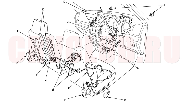
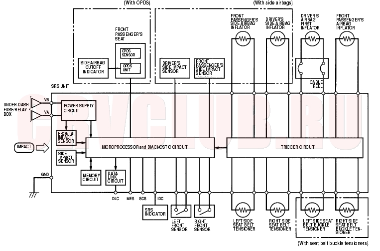
The SRS is a safety device which, when used with the seat belt, is designed to help protect the driver and front passenger in a frontal impact exceeding a certain set limit. The system consists of the SRS unit, including safing sensor and impact sensor (A), the cable reel (B), the driver's airbag (C), the front passenger's airbag (D), side airbags (E), seat belt tensioners (I), and front impact sensors (J).
Side Airbags
The side airbags (E) are in each front seat-back. They help protect the upper torso of the driver or front seat passenger during a moderate to severe side impact. Side impact sensors (F) in each door sill and in the SRS unit detect such an impact and instantly inflate the driver's or the passenger's side airbag. Only one side airbag will deploy during a side impact. If the impact is on the passenger's side, the passenger's side airbag will deploy even if there is no passenger.
Seat Belt and Seat Belt Buckle Tensioners
The seat belt and seat belt buckle tensioners (G) are linked with the SRS airbags to further increase the effectiveness of the seat belt. In a front-end collision, the tensioners instantly retract the belt and buckle firmly to secure the occupants in their seats.
OPDS
The side airbag system also includes an Occupant Position Detection System (OPDS). This system consists of sensors (K) and a OPDS unit (H) in the front passenger's seat-back. The OPDS unit sends occupant height and position data to the SRS unit. If the SRS unit determines that the front passenger is of small stature (for example, a child) and the front passenger is leaning into the side airbag deployment path, it will automatically disable the airbag. The SRS unit will also disable the airbag when the OPDS detects certain objects on the seat. When the side airbag is disabled, the Side Airbag Cutoff indicator on the instrument panel alerts the driver that the passenger's side airbag will not deploy in a side impact. When the object is removed, or the passenger sits upright, the Side Airbag Cutoff indicator will go off, alerting the driver that the side airbag will deploy in a side impact.
23-41
SRS Operation
The main circuit in the SRS unit senses and judges the force of impact and, if necessary, ignites the inflator charges. If battery voltage is too low or power is disconnected due to the impact, the voltage regulator and the back-up power circuit, respectively, will keep voltage at a constant level.
Driver's and Front Passenger's Airbag(s)
(1) The frontal impact sensor must activate, and send electric signals to the microprocessor.
(2) The microprocessor must compute the signals, and depending on the severity of the collision and whether the seat belt buckle switch is ON or OFF, it sends the appropriate signals to the airbag inflator(s).
(3) The inflators that received signals must ignite and deploy the airbag (s).
Side Airbag(s)
(1) The side impact sensors must activate, and send electric signals to the microprocessor.
(2) The microprocessor must compute the signals and send them to the side airbag inflator(s). However, the microprocessor cuts off the signals to the front passenger's side airbag if the SRS unit determines that the front passenger's head is in the deployment path of the side airbag.
(3) The inflator that received the signal must ignite and deploy the side airbag.(With Side airbags)
Self-diagnosis System
A self-diagnosis circuit is built into the SRS unit; when the ignition switch is turned ON (II), the SRS indicator comes on and goes off after about 6 seconds if the system is operating normally.
If the light does not come on, or does not go off after 6 seconds, or if it comes on while driving, it indicates an abnormality in the system. The system must be inspected and repaired as soon as possible.For better serviceability, the SRS unit memory stores a DTC that relates to the cause of the malfunction, and the unit is connected to the data link connector (DLC). This information can be read with the Honda PGM Tester when it is connected to the DLC (16P).
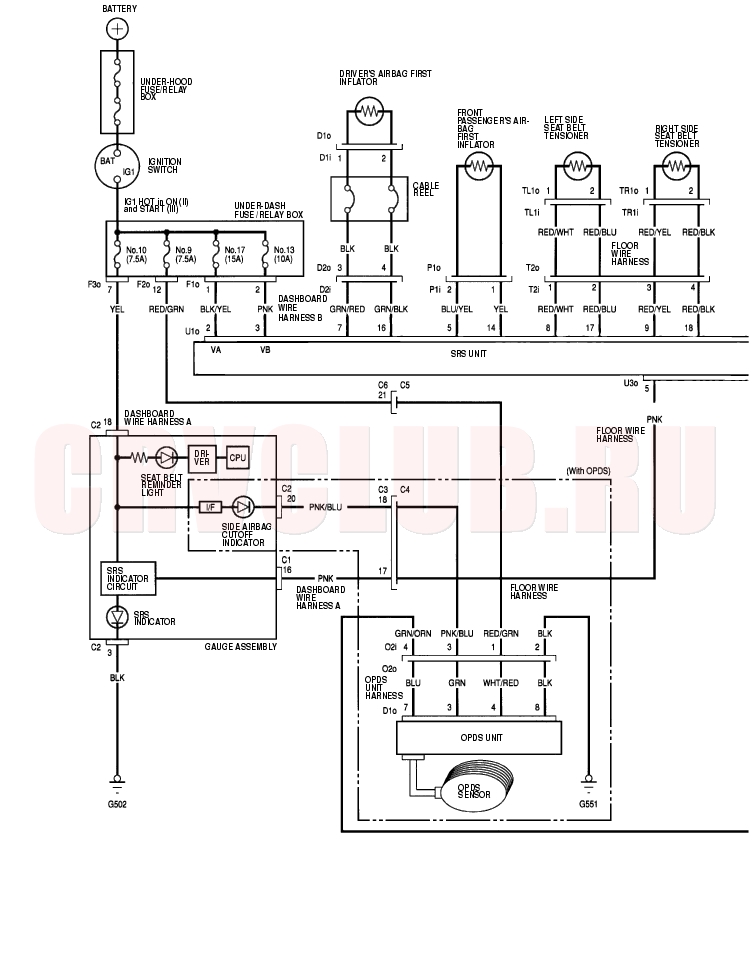
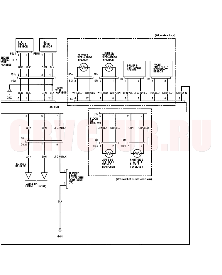
Circuit Diagram23-42
23-43
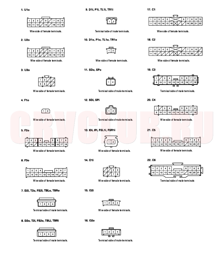
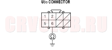
Connectors23-44
*1: The connector numbers are original in this section that are different from other sections.
(1) Spring loaded lock connector
(2) With built-in short contact connector
23-45
DTC Troubleshooting23-46
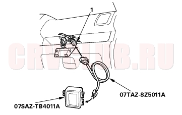
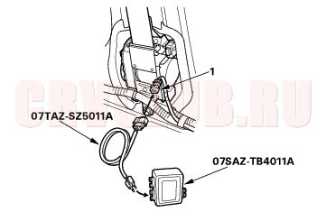
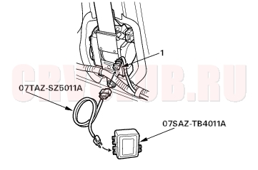
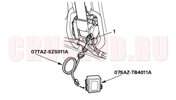
DTC 1-1: Open in Driver's Airbag Inflator
DTC 1-2: Increased Resistance in Driver's Airbag Inflator
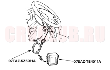
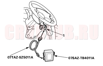
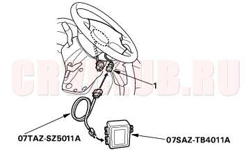
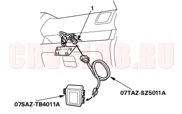
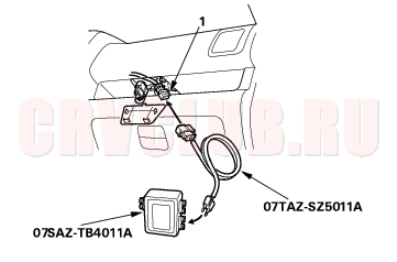
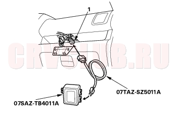
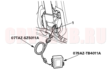
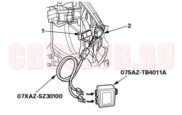
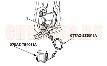
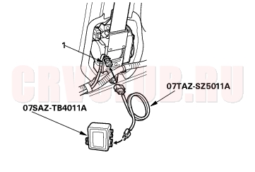
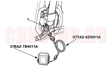
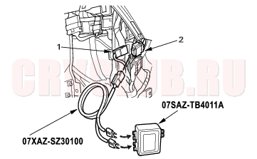
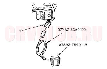
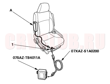
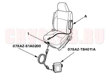
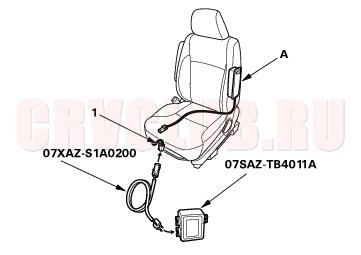
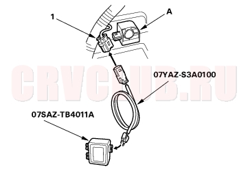
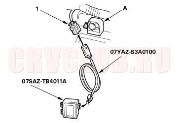
Special Tools Required
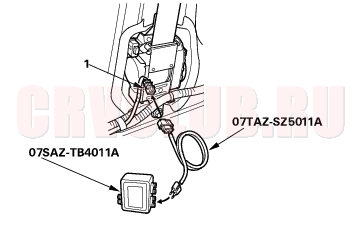
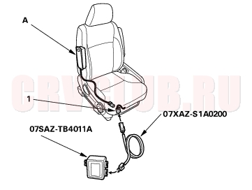
SRS inflator simulator 07SAZ-TB4011A SRS simulator lead C 07TAZ-SZ5011A
- Erase the DTC memory (see page 23-29) .
- Turn the ignition switch ON (II), and check that the SRS indicator comes on for about 6 seconds and then goes off.
Does the SRS indicator stay on?
Yes : Go to step 3.
No : Intermittent failure, system is OK at this time. Go to Troubleshooting Intermittent Failures (see page 23-29).
- Turn the ignition switch OFF. Disconnect the battery negative cable, and wait for 3 minutes.
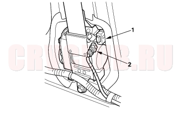
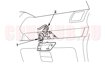
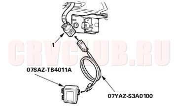
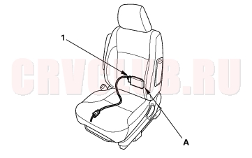
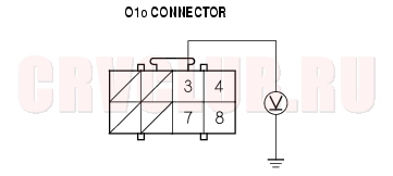
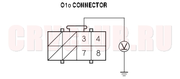
- Disconnect the D1o connector from the D1i connector (1).
- Connect the special tool (2
connector) to the D1i connector.
- Reconnect the battery negative cable.
- Erase the DTC memory.
- Read the DTC.
Is DTC 1-1 or DTC 1-2 indicated?
Yes : Go to step 9.
No : Open or increased resistance in the driver's airbag inflator; replace the driver's airbag (see page 23-135).

- Disconnect the battery negative cable, and wait for 3 minutes.
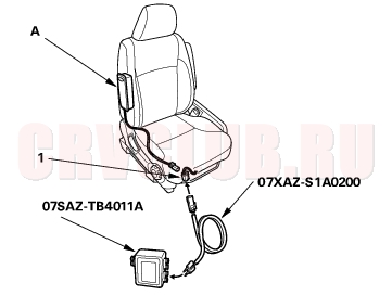
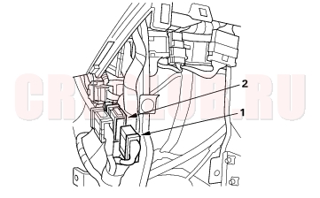
- Disconnect the P1o connector (1) from the P1i connector (2).
23-47
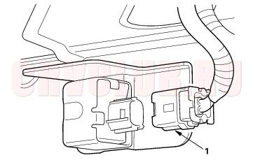
- Disconnect the TL1o and TR1o connectors (1) from the TL1i and TR1i connectors (2).
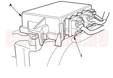
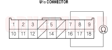
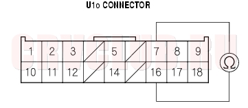
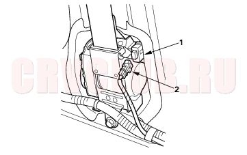
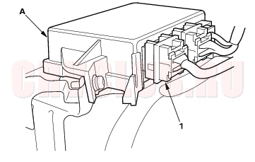
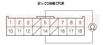
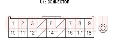
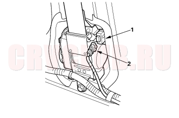
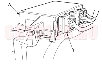
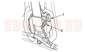
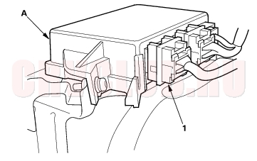
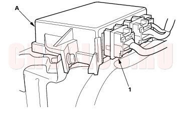
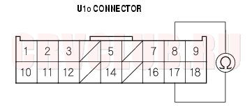
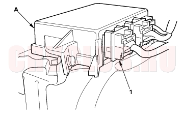
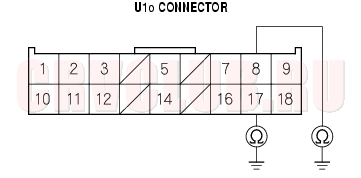
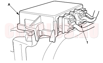
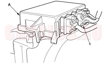
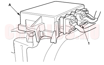
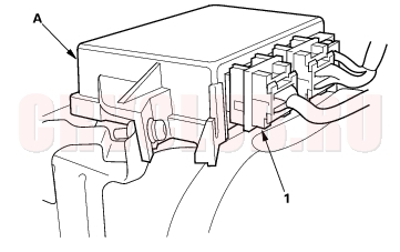
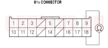
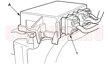
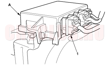
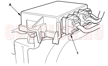
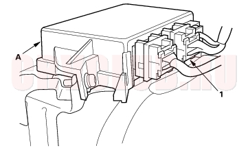
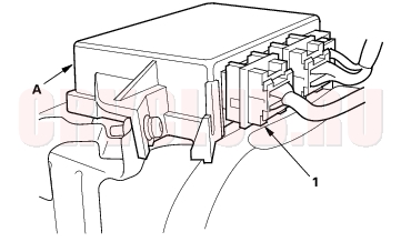
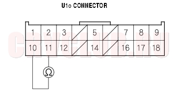
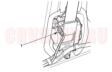
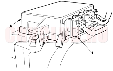
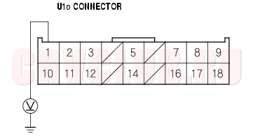
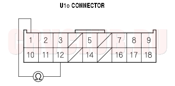
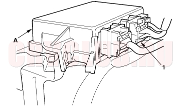
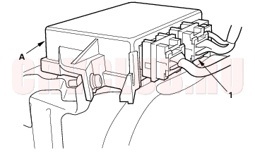
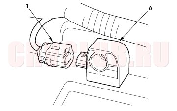
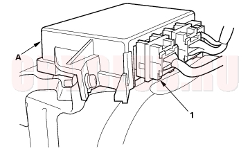
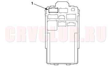
- Disconnect the U1o connector (1) from the SRS unit (A).
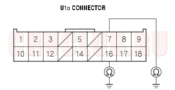
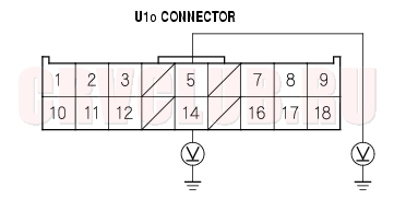
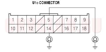
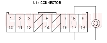
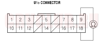
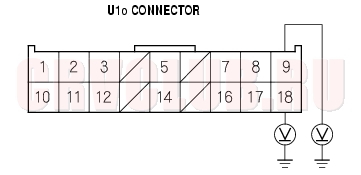
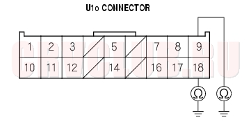
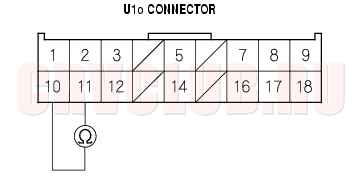
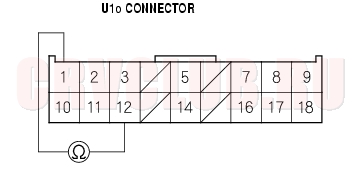
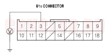
- Check resistance between the No. 7 and the No. 16 terminals of U1o connector. There should be
2.0 - 3.0
Is the resistance as specified?
Yes : Faulty SRS unit or poor contact at the U1o connector and the SRS unit, check the connection between the U1o connector and the SRS unit. If the connection is OK, replace the SRS unit (see page 23-144).
No : Open or increased resistance in dashboard wire harness B or the cable reel; replace dashboard wire harness B or the cable reel.
DTC Troubleshooting (cont'd)23-48
DTC 1-3: Short to Another Wire or Decreased Resistance in Driver's Airbag Inflator
Special Tools Required
SRS inflator simulator 07SAZ-TB4011A SRS simulator lead C 07TAZ-SZ5011A
- Erase the DTC memory (see page 23-29) .
- Turn the ignition switch ON (II), and check that the SRS indicator comes on for about 6 seconds and then goes off.
Does the SRS indicator stay on?
Yes : Go to step 3.
No : Intermittent failure, system is OK at this time. Go to Troubleshooting Intermittent Failures (see page 23-29).
- Turn the ignition switch OFF. Disconnect the battery negative cable, and wait for 3 minutes.
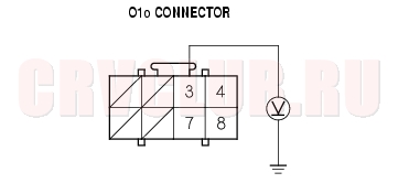
- Disconnect the D1o connector from the D1i connector (1).
- Connect the special tool (2
- Reconnect the battery negative cable.
- Erase the DTC memory.
- Read the DTC.
Is DTC 1-3 indicated?
Yes : Go to step 9.
No : Short in the driver's airbag; replace the driver's airbag (see page 23-135).
- Disconnect the battery negative cable, and wait for 3 minutes.
- Disconnect the P1o connector (1) from the P1i connector (2).
23-49
- Disconnect the TL1o and TR1o connectors (1) from the TL1i and TR1i connectors (2).
- Disconnect the U1o connector (1) from the SRS unit (A).
- Disconnect the special tool from the D1i connector.
- Check resistance between the No. 7 and the No. 16 terminals of the U1o connector. There should be 1 M
Is the resistance as specified?
Yes : Faulty SRS unit; replace the SRS unit (see page 23-144).
No : Go to step 15.
- Disconnect the cable reel from dashboard wire harness B. Check resistance between the No. 7 and the No. 16 terminals of the U1o connector. There should be 1 M
Is the resistance as specified?
Yes : Replace the cable reel.
No : Replace dashboard wire harness B.
DTC Troubleshooting (cont'd)23-50
DTC 1-4: Short to Power in Driver's Airbag Inflator
Special Tools Required
SRS inflator simulator 07SAZ-TB4011A SRS simulator lead C 07TAZ-SZ5011A
- Erase the DTC memory (see page 23-29) .
- Turn the ignition switch ON (II), and check that the SRS indicator comes on for about 6 seconds and then goes off.
Does the SRS indicator stay on?
Yes : Go to step 3.
No : Intermittent failure, system is OK at this time. Go to Troubleshooting Intermittent Failures (see page 23-29).
- Turn the ignition switch OFF. Disconnect the battery negative cable, and wait for 3 minutes.
- Disconnect the D1o connector from the D1i connector (1).
- Connect the special tool (2
- Reconnect the battery negative cable.
- Erase the DTC memory.
- Read the DTC.
Is DTC 1-4 indicated?
Yes : Go to step 9.
No : Short to power in the driver's airbag; replace the driver's airbag (see page 23-135).
- Disconnect the battery negative cable, and wait for 3 minutes.
- Disconnect the P1o connector (1) from the P1i connector (2).
- Disconnect the TL1o and TR1o connectors (1) from the TL1i and TR1i connectors (2).
23-51
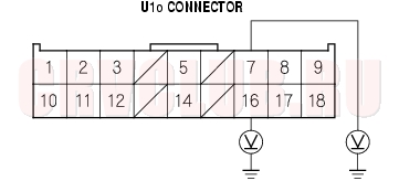
- Disconnect the U1o connector (1) from the SRS unit (A).
- Disconnect the special tool from the D1i connector.
- Reconnect the battery negative cable.
- Turn the ignition switch ON (II).
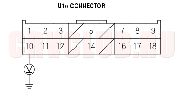
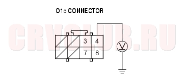
- Check for voltage between the No. 7 terminal of U1o connector and body ground, between the No. 16 terminal and body ground. There should be 0.5 V or less.
Is the voltage as specified?
Yes : Faulty SRS unit; replace the SRS unit (see page 23-144).
No : Go to step 17.
- Turn the ignition switch OFF.
- Disconnect the cable reel from the dashboard wire harness.
- Turn the ignition switch ON (II).
- Check for voltage between the No. 7 terminal of U1o connector and body ground, between the No. 16 terminal and body ground. There should be 0.5 V or less.
Is the voltage as specified?
Yes : Replace the cable reel.
No : Replace dashboard wire harness B.
DTC Troubleshooting (cont'd)23-52
DTC 1-5: Short to Ground in Driver's Airbag Inflator
Special Tools Required
SRS inflator simulator 07SAZ-TB4011A SRS simulator lead C 07TAZ-SZ5011A
- Erase the DTC memory (see page 23-29) .
- Turn the ignition switch ON (II), and check that the SRS indicator comes on for about 6 seconds and then goes off.
Does the SRS indicator stay on?
Yes : Go to step 3.
No : Intermittent failure, system is OK at this time. Go to Troubleshooting Intermittent Failures (see page 23-29).
- Turn the ignition switch OFF. Disconnect the battery negative cable, and wait for 3 minutes.
- Disconnect the D1o connector from the D1i connector (1).
- Connect the special tool (2
- Reconnect the battery negative cable.
- Erase the DTC memory.
- Read the DTC.
Is DTC 1-5 indicated?
Yes : Go to step 9.
No : Short to ground in the driver's airbag inflator; replace the driver's airbag (see page 23-135).
- Disconnect the battery negative cable, and wait for 3 minutes.
- Disconnect the P1o connector (1) from the P1i connector (2).
- Disconnect the TL1o and TR1o connectors (1) from the TL1i and TR1i connectors (2).
23-53
- Disconnect the U1o connector (1) from the SRS unit (A).
- Disconnect the special tool from the D1i connector.
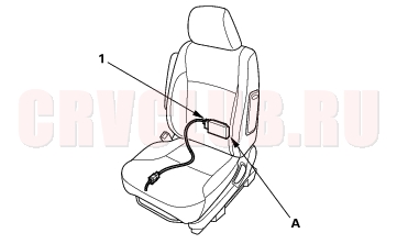
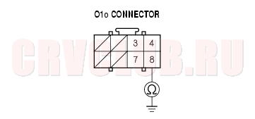
- Check resistance between the No. 7 terminal of U1o connector and body ground, between the No.16 terminal and body ground. There should be 1 M
Is the resistance as specified?
Yes : Faulty SRS unit; replace the SRS unit (see page 23-144).
No : Go to step 15.
- Disconnect the cable reel from the dashboard wire harness.
- Check resistance between the No. 7 terminal of U1o connector and body ground, between the No. 16 terminal and body ground. There should be
1 M
Is the resistance as specified?
Yes : Replace the cable reel.
No : Replace dashboard wire harness B.
DTC Troubleshooting (cont'd)23-54
DTC 2-1: Open in Front Passenger's Airbag Inflator
DTC 2-2: Increased Resistance in Front Passenger's Airbag Inflator
Special Tools Required
SRS inflator simulator 07SAZ-TB4011A SRS simulator lead C 07TAZ-SZ5011A
- Erase the DTC memory (see page 23-29) .
- Turn the ignition switch ON (II), and check that the SRS indicator comes on for about 6 seconds and then goes off.
Does the SRS indicator stay on?
Yes : Go to step 3.
No : Intermittent failure, system is OK at this time.Go to Troubleshooting Intermittent Failures (see page 23-29).
- Turn the ignition switch OFF. Disconnect the battery negative cable, and wait for 3 minutes.
- Disconnect the P1o connector from the P1i connector (1).
- Connect the special tool (2
- Reconnect the battery negative cable.
- Erase the DTC memory.
- Read the DTC.
Is DTC 2-1 or DTC 2-2 indicated?
Yes : Go to step 9.
No : Open or increased resistance in the front passenger's airbag inflator; replace the front passenger's airbag (see page 23-136).
- Disconnect the battery negative cable, and wait for 3 minutes.
- Disconnect the D1o connector (1) from the D1i connector (2).
- Disconnect the TL1o and TR1o connectors (1) from the TL1i and TR1i connectors (2).
23-55
- Disconnect the U1o connector (1) from the SRS unit (A).
- Check resistance between the No. 5 and No. 14 terminals of U1o connector. There should be
2.0 - 3.0
Is the resistance as specified?
Yes : Faulty SRS unit or poor contact at the U1o connector; check the connection between U1o connector and the SRS unit. If the connector is OK, replace the SRS unit (see page 23-144).
No : Open or increased resistance in the dashboard wire harness B; replace dashboard wire harness B.
DTC 2-3: Short to Another Wire or Decreased Resistance in Front Passenger's Airbag Inflator
Special Tools Required
SRS inflator simulator 07SAZ-TB4011A SRS simulator lead C 07TAZ-SZ5011A
- Erase the DTC memory (see page 23-29) .
- Turn the ignition switch ON (II), and check that the SRS indicator comes on for about 6 seconds and then goes off.
Does the SRS indicator stay on?
Yes : Go to step 3.
No : Intermittent failure, system is OK at this time.Go to Troubleshooting Intermittent Failures (see page 23-29).
- Turn the ignition switch OFF. Disconnect the battery negative cable, and wait for 3 minutes.
- Disconnect the P1o connector from the P1i connector (1).
- Connect the special tool (2
- Reconnect the battery negative cable.
- Erase the DTC memory.
DTC Troublshooting (cont'd)23-56
Is DTC 2-3 indicated?
Yes : Go to step 9.
No : Short in the front passenger's airbag inflator; replace the front passenger's airbag (see page 23-136).
- Disconnect the battery negative cable, and wait for 3 minutes.
- Disconnect the D1o connector (1) from the D1i connector (2).
- Disconnect the TL1o and TR1o connectors (1) from the TL1i and TR1i connectors (2).
- Disconnect the U1o connector (1) from the SRS unit (A).
- Disconnect the special tool from the P1i connector.
- Check resistance between the No. 5 and No. 14 terminals of U1o connector. There should be 1
Is the resistance as specified?
Yes : Faulty SRS unit; replace the SRS unit (see page 23-144).
No : Short in dashboard wire harness B; replace dashboard wire harness B.
23-57
DTC 2-4: Short to Power in Front Passenger's Airbag Inflator
Special Tools Required
SRS inflator simulator 07SAZ-TB4011A SRS simulator lead C 07TAZ-SZ5011A
- Erase the DTC memory (see page 23-29) .
- Turn the ignition switch ON (II), and check that the SRS indicator comes on for about 6 seconds and then goes off.
Does the SRS indicator stay on?
Yes : Go to step 3.
No : Intermittent failure, system is OK at this time.Go to Troubleshooting Intermittent Failures (see page 23-29).
- Turn the ignition switch OFF. Disconnect the battery negative cable, and wait for 3 minutes.
- Disconnect the P1o connector from the P1i connector (1).
- Connect the special tool (2
- Reconnect the battery negative cable.
- Erase the DTC memory.
- Read the DTC.
Is DTC 2-4 indicated?
Yes : Go to step 9.
No : Short to power in the front passenger's airbag inflator; replace the front passenger's airbag (see page 23-136).
- Disconnect the battery negative cable, and wait for 3 minutes.
- Disconnect the D1o connector (1) from the D1i connector (2).
- Disconnect the TL1o and TR1o connectors (1) from the TL1i and TR1i connectors (2).
DTC Troubleshooting (cont'd)23-58
- Disconnect the U1o connector (1) from the SRS unit (A).
- Disconnect the special tool from the P1i connector.
- Reconnect the battery negative cable.
- Turn the ignition switch ON (II).
- Check for voltage between the No. 5 terminal of the U1o connector and body ground, and between the No. 14 terminal and body ground. There should be 0.5 V or less.
Is the voltage as specified?
Yes : Faulty SRS unit; replace the SRS unit (see page 23-144).
No : Short to power in the dashboard wire harness B; replace the dashboard wire harness B.
DTC 2-5: Short to Ground in Front Passenger's Airbag Inflator
Special Tools Required
SRS inflator simulator 07SAZ-TB4011A SRS simulator lead C 07TAZ-SZ5011A
- Erase the DTC memory (see page 23-29) .
- Turn the ignition switch ON (II), and check that the SRS indicator comes on for about 6 seconds and then goes off.
Does the SRS indicator stay on?
Yes : Go to step 3.
No : Intermittent failure, system is OK at this time.Go to Troubleshooting Intermittent Failures (see page 23-29).
- Turn the ignition switch OFF. Disconnect the battery negative cable, and wait for 3 minutes.
- Disconnect the P1o connector from the P1i connector (1).
- Connect the special tool (2
23-59
Is DTC 2-5 indicated?
Yes : Go to step 9.
No : Short to ground in the front passenger's airbag inflator; replace the front passenger's airbag (see page 23-136).
- Disconnect the battery negative cable, and wait for 3 minutes.
- Disconnect the D1o connector (1) from the D1i connector (2).
- Disconnect the TL1o and TR1o connectors (1) from the TL1i and TR1i connectors (2).
- Disconnect the U1o connector (1) from the SRS unit (A).
- Disconnect the special tool from the P1i connector.
- Check resistance between the No. 5 terminal of the U1o connector and body ground, and between the No. 14 terminal and body ground. There should be 1 M
Is the resistance as specified?
Yes : Faulty SRS unit; replace the SRS unit (see page 23-144).
No : Short to ground in dashboard wire harness B; replace dashboard wire harness B.
DTC Troubleshooting (cont'd)23-60
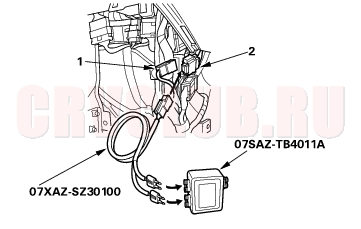
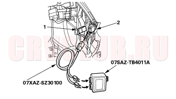
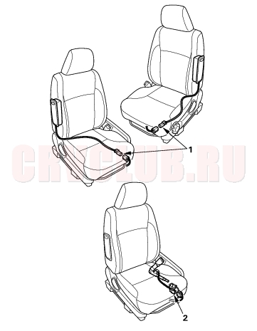
DTC 3-1: Open in Left Side Seat Belt Tensioner
DTC 3-2: Increased Resistance in Left Side Seat Belt Tensioner
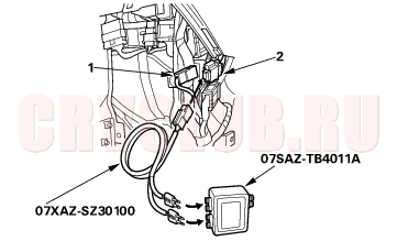
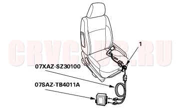
Special Tools Required
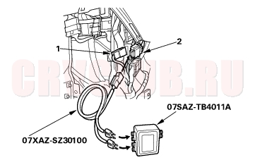
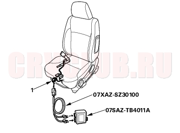
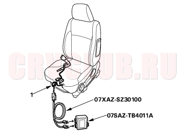
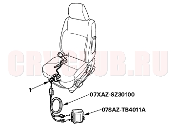
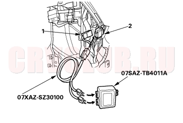
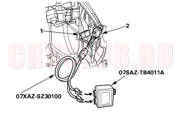
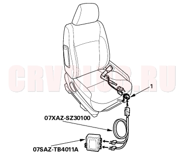
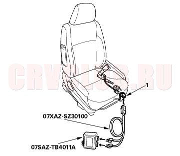
SRS inflator simulator 07SAZ-TB4011A SRS simulator lead C 07TAZ-SZ5011A SRS simulator lead F 07XAZ-SZ30100
- Erase the DTC memory (see page 23-29) .
- Turn the ignition switch ON (II), and check that the SRS indicator comes on for about 6 seconds and then goes off.
Does the SRS indicator stay on?
Yes : Go to step 3.
No : Intermittent failure, system is OK at this time. Go to Troubleshooting Intermittent Failures (see page 23-29).
- Turn the ignition switch OFF. Disconnect the battery negative cable, and wait for 3 minutes.
- Disconnect the TL1o connector from the TL1i connector (1).
- Connect the special tool (2
- Reconnect the battery negative cable.
- Erase the DTC memory.
- Read the DTC.
Is DTC 3-1 or DTC 3-2 indicated?
Yes : Go to step 9.
No : Open or increased resistance in the left side seat belt tensioner; replace the left side seat belt (see page 23-4).
- Disconnect the battery negative cable, and wait for 3 minutes.
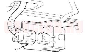
- Disconnect the T2o connector (1) from the T2i connector (2).
- Connect the special tool (2
- Reconnect the battery negative cable.
- Erase the DTC memory.
- Read the DTC.
Is DTC 3-1 or DTC 3-2 indicated?
Yes : Go to step 15.
No : Open or increased resistance in the floor wire harness; replace the floor wire harness.
23-61
- Disconnect the D1o connector (1), P1o connector (2), and TR1i connector (3).
- Disconnect the U1o connector (1) from the SRS unit (A).
- Check resistance between the No. 8 terminal and the No. 17 terminal of U1o connector. There should be 2.0 - 3.0
Is the resistance as specified?
Yes : Faulty SRS unit or poor contact at U1o connector and the SRS unit. Check the connection between the connector and the SRS unit. If the connection is OK, replace the SRS unit (see page 23-144).
No : Open or increased resistance in dashboard wire harness B; replace dashboard wire harness B.
DTC Troubleshooting (cont'd)23-62
DTC 3-3: Short to Another Wire or Decreased Resistance in Left Side Seat Belt Tensioner
Special Tools Required
SRS inflator simulator 07SAZ-TB4011A SRS simulator lead C 07TAZ-SZ5011A SRS simulator lead F 07XAZ-SZ30100
- Erase the DTC memory (see page 23-29) .
- Turn the ignition switch ON (II), and check that the SRS indicator comes on for about 6 seconds and then goes off.
Does the SRS indicator stay on?
Yes : Go to step 3.
No : Intermittent failure, system is OK at this time. Go to Troubleshooting Intermittent Failures (see page 23-29).
- Turn the ignition switch OFF. Disconnect the battery negative cable, and wait for 3 minutes.
- Disconnect the TL1o connector from the TL1i connector (1).
- Connect the special tool (2
- Reconnect the battery negative cable.
- Erase the DTC memory.
- Read the DTC.
Is DTC 3-3 indicated?
Yes : Go to step 9.
No : Short in the left side seat belt tensioner; replace the left side seat belt (see page 23-4).
- Disconnect the battery negative cable, and wait for 3 minutes.
- Disconnect the T2o connector (1) from the T2i connector (2).
- Connect the special tool (2
- Reconnect the battery negative cable.
- Erase the DTC memory.
- Read the DTC.
Is DTC 3-3 indicated?
Yes : Go to step 15.
No : Short in the floor wire harness; replace the floor wire harness.
23-63
- Disconnect the D1o connector (1), P1o connector (2), and TR1i connector (3).
- Disconnect the U1o connector (1) from the SRS unit (A).
- Disconnect the special tool from the T2i connector.
- Check resistance between the No. 8 terminal and the No. 17 terminal U1o connector. There should be 1 M
Is the resistance as specified?
Yes : Faulty SRS unit; replace the SRS unit (see page 23-144).
No : Short in dashboard wire harness B; replace dashboard wire harness B.
DTC Troubleshooting (cont'd)23-64
DTC 3-4: Short to Power in Left side Seat Belt Tensioner
Special Tools Required
SRS inflator simulator 07SAZ-TB4011A SRS simulator lead C 07TAZ-SZ5011A SRS simulator lead F 07XAZ-SZ30100
- Erase the DTC memory (see page 23-29) .
- Turn the ignition switch ON (II), and check that the SRS indicator comes on for about 6 seconds and then goes off.
Does the SRS indicator stay on?
Yes : Go to step 3.
No : Intermittent failure, system is OK at this time. Go to Troubleshooting Intermittent Failures (see page 23-29).
- Turn the ignition switch OFF. Disconnect the battery negative cable, and wait for 3 minutes.
- Disconnect the TL1o connector from the TL1i connector (1).
- Connect the special tool (2
- Reconnect the battery negative cable.
- Erase the DTC memory.
- Read the DTC.
Is DTC 3-4 indicated?
Yes : Go to step 9.
No : Short to power in the left side seat belt tensioner; replace the left side seat belt (see page 23-4).
- Disconnect the battery negative cable, and wait for 3 minutes.
- Disconnect the T2o connector (1) from the T2i connector (2).
- Connect the special tool (2
- Reconnect the battery negative cable.
- Erase the DTC memory.
- Read the DTC.
Is DTC 3-4 indicated?
Yes : Go to step 15.
No : Short to power in the floor wire harness; replace the floor wire harness.
23-65
- Disconnect the D1o connector (1), P1o connector (2), and TR1i connector (3).
- Disconnect the U1o connector (1) from the SRS unit (A).
- Disconnect the special tool (2
- Reconnect the battery negative cable.
- Turn the ignition switch ON (II).
- Check for voltage between the No. 8 terminal of U1o connector and body ground, and between the No. 17 terminal and body ground. There should be 0.5 V or less.
Is the voltage as specified?
Yes : Faulty SRS unit; replace the SRS unit (see page 23-144).
No : Short to power in dashboard wire harness B; replace dashboard wire harness B.
DTC Troubleshooting (cont'd)23-66
DTC 3-5: Short to Ground in Left Side Seat Belt Tensioner
Special Tools Required
SRS inflator simulator 07SAZ-TB4011A SRS simulator lead C 07TAZ-SZ5011A SRS simulator lead F 07XAZ-SZ30100
- Erase the DTC memory (see page 23-29) .
- Turn the ignition switch ON (II), and check that the SRS indicator comes on for about 6 seconds and then goes off.
Does the SRS indicator stay on?
Yes : Go to step 3.
No : Intermittent failure, system is OK at this time. Go to Troubleshooting Intermittent Failures (see page 23-29).
- Turn the ignition switch OFF. Disconnect the battery negative cable, and wait for 3 minutes.
- Disconnect the TL1o connector from the TL1i connector (1).
- Connect the special tool (2
- Reconnect the battery negative cable.
- Erase the DTC memory.
- Read the DTC.
Is DTC 3-5 indicated?
Yes : Go to step 9.
No : Short to ground in the left side seat belt tensioner; replace the left side seat belt (see page 23-4).
- Disconnect the battery negative cable, and wait for 3 minutes.
- Disconnect the T2o connector (1) from the T2i connector (2).
- Connect the special tool (2
- Reconnect the battery negative cable.
- Erase the DTC memory.
- Read the DTC.
Is DTC 3-5 indicated?
Yes : Go to step 15.
No : Short to ground in the floor wire harness; replace the floor wire harness.
23-67
- Disconnect the D1o connector (1), P1o connector (2), and TR1i connector (3).
- Disconnect the U1o connector (1) from the SRS unit (A).
- Disconnect the special tool from the T2i connector.
- Check resistance between the No. 8 terminal of U1o connector and body ground, and between the No. 17 terminal and body ground. There should be 1 M
Is the resistance as specified?
Yes : Faulty SRS unit; replace the SRS unit (see page 23-144).
No : Short to ground in dashboard wire harness B; replace dashboard wire harness B.
DTC Troubleshooting (cont'd)23-68
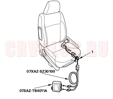
DTC 21-1: Open in Left Side Seat Belt Buckle Tensioner
DTC 21-2: Increased Resistance in Left Side Seat Belt Buckle Tensioner
Special Tools Required
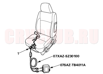
SRS inflator simulator 07SAZ-TB4011A SRS simulator lead F 07XAZ-SZ30100
- Erase the DTC memory (see page 23-29) .
- Turn the ignition switch ON (II), and check that the SRS indicator comes on for about 6 seconds and then goes off.
Does the SRS indicator stay on?
Yes : Go to step 3.
No : Intermittent failure, system is OK at this time. Go to Troubleshooting Intermittent Failures (see page 23-29).
- Turn the ignition switch OFF. Disconnect the battery negative cable, and wait for 3 minutes.
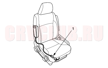
- Disconnect the TBLo connector from the TBLi connector (1).
- Connect the special tool (2
- Reconnect the battery negative cable.
- Erase the DTC memory.
- Read the DTC.
Is DTC 21-1 or DTC 21-2 indicated?
Yes : Go to step 9.
No : Open or increased resistance in the left side seat belt buckle tensioner; replace the left side seat belt buckle.
- Disconnect the battery negative cable, and wait for 3 minutes.
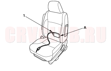
- Disconnect the SDo and SPo connectors (1) and the TBRo connector (2).
23-69
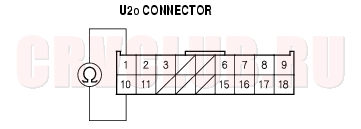
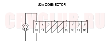
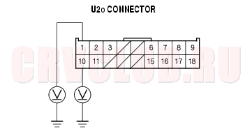
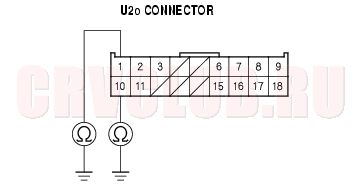
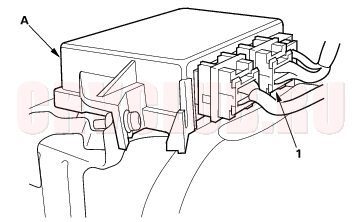
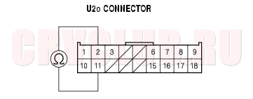
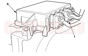
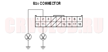
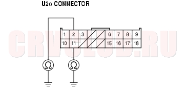
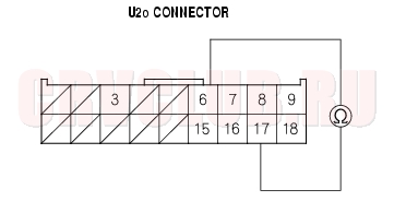
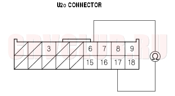
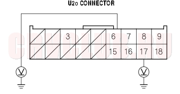
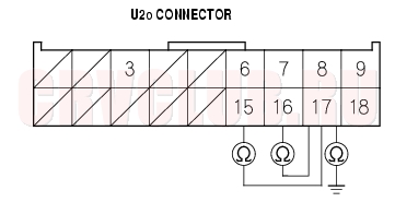
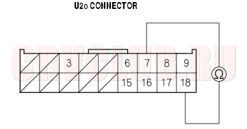
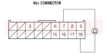
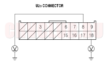
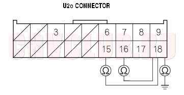
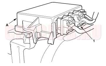
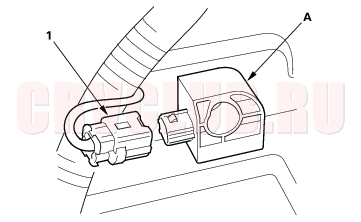
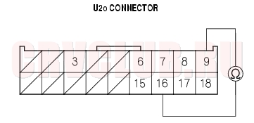
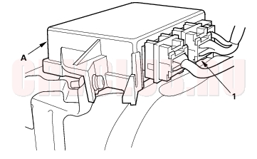
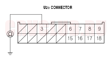
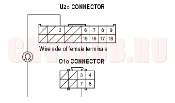
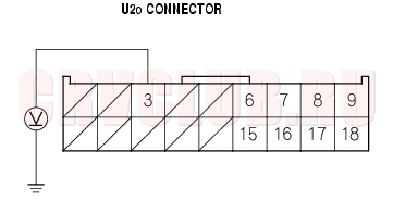
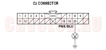
- Disconnect the U2o connector (1) from the SRS unit (A).
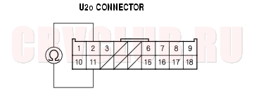
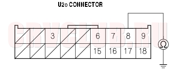
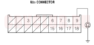
- Check resistance between the No. 1 and No. 10 terminals of the U2o connector. There should be 2.0 - 3.0
Is the resistance as specified?
Yes : Faulty SRS unit or poor contact at U2o connector and at the SRS unit. Check the connection between the connector and the SRS unit. If the connection is OK, replace the SRS unit (see page 23-144).
No : Open or increased resistance in the floor wire harness; replace the floor wire harness.
DTC 21-3: Short to Auother Wire or Decreased Resistance in Left Side Seat Belt Buckle Tensioner
Special Tools Required
SRS inflator simulator 07SAZ-TB4011A SRS simulator lead F 07XAZ-SZ30100
- Erase the DTC memory (see page 23-29) .
- Turn the ignition switch ON (II), and check that the SRS indicator comes on for about 6 seconds and then goes off.
Does the SRS indicator stay on?
Yes : Go to step 3.
No : Intermittent failure, system is OK at this time. Go to Troubleshooting Intermittent Failures (see page 23-29).
- Turn the ignition switch OFF. Disconnect the battery negative cable, and wait for 3 minutes.
- Disconnect the TBLo connector from the TBLi connector (1).
- Connect the special tool (2
- Reconnect the battery negative cable.
- Erase the DTC memory.
DTC Troubleshooting (cont'd)23-70
Is DTC 21-3 indicated?
Yes : Go to step 9.
No : Open or increased resistance in the left side seat belt buckle tensioner; replace the left side seat belt buckle.
- Disconnect the battery negative cable, and wait for 3 minutes.
- Disconnect the SDo and SPo connectors (1) and the TBRo connector (2).
- Disconnect the U2o connector (1) from the SRS unit (A).
- Disconnect the special tool (2
- Check resistance between the No. 1 and No. 10 terminals of the U2o connector. There should be 2.0 - 3.0
Is the resistance as specified?
Yes : Faulty SRS unit or poor contact at U2o connector and at the SRS unit. Check the connection between the connector and the SRS unit. If the connection is OK, replace the SRS unit (see page 23-144).
No : Open or increased resistance in the floor wire harness; replace the floor wire harness.
23-71
DTC 21-4: Short to Power in Left Side Seat Belt Buckle Tensioner
Special Tools Required
SRS inflator simulator 07SAZ-TB4011A SRS simulator lead F 07XAZ-SZ30100
- Erase the DTC memory (see page 23-29) .
- Turn the ignition switch ON (II), and check that the SRS indicator comes on for about 6 seconds and then goes off.
Does the SRS indicator stay on?
Yes : Go to step 3.
No : Intermittent failure, system is OK at this time. Go to Troubleshooting Intermittent Failures (see page 23-29).
- Turn the ignition switch OFF. Disconnect the battery negative cable, and wait for 3 minutes.
- Disconnect the TBLo connector from the TBLi connector (1).
- Connect the special tool (2
- Reconnect the battery negative cable.
- Erase the DTC memory.
- Read the DTC.
Is DTC 3-9 or 21-4 indicated?
Yes : Go to step 9.
No : Short to power in the left side seat belt buckle tensioner; replace the left side seat belt buckle.
- Disconnect the battery negative cable, and wait for 3 minutes.
- Disconnect the SDo and SPo connectors (1) and the TBRo connector (2).
DTC Troubleshooting (cont'd)23-72
- Disconnect the U2o connector (A) from the SRS unit (A).
- Disconnect the special tool (2
- Reconnect the battery negative cable.
- Turn the ignition switch ON (II).
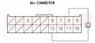
- Check for voltage between the No. 1 terminal of the U2o connector and body ground. and between the No. 10 terminal and body ground. There should be 0.5 V or less.
Is the voltage as specified?
Yes : Faulty SRS unit; replace the SRS unit (see page 23-144).
No : Short to power in the floor wire harness; replace the floor wire harness.
DTC 21-5: Short to Ground in Left Side Seat Belt Buckle Tensioner
Special Tools Required
SRS inflator simulator 07SAZ-TB4011A SRS simulator lead F 07XAZ-SZ30100
- Erase the DTC memory (see page 23-29) .
- Turn the ignition switch ON (II), and check that the SRS indicator light comes on for about 6 seconds and then goes off.
Does the SRS indicator light stay on?
Yes : Go to step 3.
No : Intermittent failure, system is OK at this time. Go to Troubleshooting Intermittent Failures (see page 23-29).
- Turn the ignition switch OFF. Disconnect the battery negative cable, and wait for 3 minutes.
- Disconnect the TBLo connector from the TBLi connector (1).
- Connect the special tool (2
- Reconnect the battery negative cable.
- Erase the DTC memory.
23-73
Is DTC 21-5 indicated?
Yes : Go to step 9.
No : Short to ground in the left side seat belt buckle tensioner; replace the left side seat belt buckle.
- Disconnect the battery negative cable, and wait for 3 minutes.
- Disconnect the SDo and SPo connectors (1) and the TBRo connector (2).
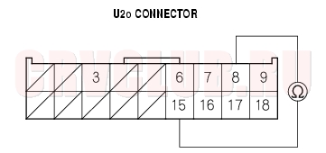
- Disconnect the U2o connector (1) from the SRS unit (A).
- Disconnect the special tool (2
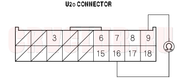
- Check resistance between the No. 1 terminal of the U2o connector and body ground. and between the No. 10 terminal and body ground. There should be 1 M
Is the resistance as specified?
Yes : Faulty SRS unit; replace the SRS unit (see page 23-144).
No : Short to ground in the floor wire harness; replace the floor wire harness.
DTC Troubleshooting (cont'd)23-74
DTC 4-1: Open in Right Side Seat Belt Tensioner
DTC 4-2: Increase Resistance in Right Side Seat Belt Tensioner
Special Tools Required
SRS inflator simulator 07SAZ-TB4011A SRS simulator lead C 07TAZ-SZ5011A SRS simulator lead F 07XAZ-SZ30100
- Erase the DTC memory (see page 23-29) .
- Turn the ignition switch ON (II), and check that the SRS indicator comes on for about 6 seconds and then goes off.
Does the SRS indicator stay on?
Yes : Go to step 3.
No : Intermittent failure, system is OK at this time. Go to Troubleshooting Intermittent Failures (see page 23-29).
- Turn the ignition switch OFF. Disconnect the battery negative cable, and wait for 3 minutes.
- Disconnect the TR1o connector from the TR1i connector (1).
- Connect the special tool (2
- Reconnect the battery negative cable.
- Erase the DTC memory.
- Read the DTC.
Is DTC 4-1 or DTC 4-2 indicated?
Yes : Go to step 9.
No : Open or increased resistance in the right side seat belt tensioner; replace the right side seat belt (see page 23-4).
- Disconnect the battery negative cable, and wait for three minutes.
- Disconnect the T2o connector (1) from the T2i connector (2).
- Connect the special tool (2
- Reconnect the battery negative cable.
- Erase the DTC memory.
- Read the DTC.
Is DTC 4-1 indicated?
Yes : Go to step 15.
No : Open or increased resistance in the floor wire harness; replace the floor wire harness.
23-75
- Disconnect the battery negative cable, and wait for 3 minutes.
- Disconnect the D1o connector (1), P1o connector (2), and TL1i connector (3).
- Disconnect the U1o connector (1) from the SRS unit (A).
- Check resistance between the No. 9 terminal and the No. 18 terminal of U1o connector. There should be 2.0 - 3.0
Is the resistance as specified?
Yes : Faulty SRS unit or poor contact at U1o connector and the SRS unit. Check the connection between connector and the SRS unit. If the connection is OK, replace the SRS unit (see page 23-144).
No : Open or increased resistance in dashboard wire harness B; replace dashboard wire harness B.
DTC Troubleshooting (cont'd)23-76
DTC 4-3: Short to Another Wire or Decreased Resistance in Right Side Seat Belt Tensioner
Special Tools Required
SRS inflator simulator 07SAZ-TB4011A SRS simulator lead C 07TAZ-SZ5011A SRS simulator lead F 07XAZ-SZ30100
- Erase the DTC memory (see page 23-29) .
- Turn the ignition switch ON (II), and check that the SRS indicator comes on for about 6 seconds and then goes off.
Does the SRS indicator stay on?
Yes : Go to step 3.
No : Intermittent failure, system is OK at this time. Go to Troubleshooting Intermittent Failures (see page 23-29).
- Turn the ignition switch OFF. Disconnect the battery negative cable, and wait for 3 minutes.
- Disconnect the TR1o connector from the TR1i connector (1).
- Connect the special tool (2
- Reconnect the battery negative cable.
- Erase the DTC memory.
- Read the DTC.
Is DTC 4-3 indicated?
Yes : Go to step 9.
No : Short in the right side seat belt tensioner; replace the right side seat belt (see page 23-4).
- Disconnect the battery negative cable, and wait for 3 minutes.
- Disconnect the T2o connector (1) from the T2i connector (2).
- Connect the special tool (2
- Reconnect the battery negative cable.
- Erase the DTC memory.
- Read the DTC.
Is DTC 4-3 indicated?
Yes : Go to step 15.
No : Short in the floor wire harness; replace the floor wire harness.
23-77
- Disconnect the D1o connector (1), P1o connector (2), and TL1i connector (3).
- Disconnect the U1o connector (1) from the SRS unit (A).
- Disconnect the special tool from the T2i connector.
- Check resistance between the No. 9 terminal and the No. 18 terminal of U1o connector. There should be 1 M
Is the resistance as specified?
Yes : Faulty SRS unit; replace the SRS unit (see page 23-144).
No : Short in dashboard wire harness B; replace dashboard wire harness B.
DTC Troubleshooting (cont'd)23-78
DTC 4-4: Short to Power in Right Side Seat Belt Tensioner
Special Tools Required
SRS inflator simulator 07SAZ-TB4011A SRS simulator lead C 07TAZ-SZ5011A SRS simulator lead F 07XAZ-SZ30100
- Erase the DTC memory (see page 23-29) .
- Turn the ignition switch ON (II), and check that the SRS indicator comes on for about 6 seconds and then goes off.
Does the SRS indicator stay on?
Yes : Go to step 3.
No : Intermittent failure, system is OK at this time. Go to Troubleshooting Intermittent Failures (see page 23-29).
- Turn the ignition switch OFF. Disconnect the battery negative cable, and wait for 3 minutes.
- Disconnect the TR1o connector from the TR1i connector (1).
- Connect the special tool (2
- Reconnect the battery negative cable.
- Erase the DTC memory.
- Read the DTC.
Is DTC 4-4 indicated?
Yes : Go to step 9.
No : Short to power in the right side seat belt tensioner; replace the right side seat belt (see page 23-4).
- Disconnect the battery negative cable, and wait for 3 minutes.
- Disconnect the T2o connector (1) from the T2i connector (2).
- Connect the special tool (2
- Reconnect the battery negative cable.
- Erase the DTC memory.
- Read the DTC.
Is DTC 4-4 indicated?
Yes : Go to step 15.
No : Short to power in the floor wire harness; replace the floor wire harness.
23-79
- Disconnect the battery negative cable, and wait for 3 minutes.
- Disconnect the D1o connector (1), P1o connector (2), and TL1i connector (3).
- Disconnect the U1o connector (1) from the SRS unit (A).
- Disconnect the special tool from the T2i connector.
- Reconnect the battery negative cable.
- Turn the ignition switch ON (II).
- Check for voltage between the No. 9 terminal of U1o connector and body ground, and between the No. 18 terminal and body ground. There should be 0.5 V or less.
Is the voltage as specified?
Yes : Faulty SRS unit; replace the SRS unit (see page 23-144).
No : Short to power in dashboard wire harness B; replace dashboard wire harness B.
DTC Troubleshooting (cont'd)23-80
DTC 4-5: Short to Ground in Right Side Seat Belt Tensioner
Special Tools Required
SRS inflator simulator 07SAZ-TB4011A SRS simulator lead C 07TAZ-SZ5011A SRS simulator lead F 07XAZ-SZ30100
- Erase the DTC memory (see page 23-29) .
- Turn the ignition switch ON (II), and check that the SRS indicator comes on for about 6 seconds and then goes off.
Does the SRS indicator stay on?
Yes : Go to step 3.
No : Intermittent failure, system is OK at this time. Go to Troubleshooting Intermittent Failures (see page 23-29).
- Turn the ignition switch OFF. Disconnect the battery negative cable, and wait for 3 minutes.
- Disconnect the TR1o connector from the TR1i connector (1).
- Connect the special tool (2
- Reconnect the battery negative cable.
- Erase the DTC memory.
- Read the DTC.
Is DTC 4-5 indicated?
Yes : Go to step 9.
No : Short to ground in the right side seat belt tensioner; replace the right side seat belt (see page 23-4).
- Disconnect the battery negative cable, and wait for 3 minutes.
- Disconnect the T2o connector (1) from the T2i connector (2).
- Connect the special tool (2
- Reconnect the battery negative cable.
- Erase the DTC memory.
- Read the DTC.
Is DTC 4-5 indicated?
Yes : Go to step 15.
No : Short to ground in the floor wire harness; replace the floor wire harness.
23-81
- Disconnect the D1o connector (1), P1o connector (2), and TL1i connector (3).
- Disconnect the U1o connector (1) from the SRS unit (A).
- Disconnect the special tool (2
- Check resistance between the No. 9 terminal of U1o connector and body ground, and between the No. 18 terminal and body ground. There should be 1 M
Is the resistance as specified?
Yes : Faulty SRS unit; replace the SRS unit (see page 23-144).
No : Short to ground in dashboard wire harness B; replace dashboard wire harness B.
DTC Troubleshooting (cont'd)23-82
DTC 22-1: Open in Right Side Seat Belt Buckle Tensioner
DTC 22-2: Increased Resistance in Right Side Seat Belt Buckle Tensioner
Special Tools Required
SRS inflator simulator 07SAZ-TB4011A SRS simulator lead F 07XAZ-SZ30100
- Erase the DTC memory (see page 23-29) .
- Turn the ignition switch ON (II), and check that the SRS indicator comes on for about 6 seconds and then goes off.
Does the SRS indicator stay on?
Yes : Go to step 3.
No : Intermittent failure, system is OK at this time. Go to Troubleshooting Intermittent Failures (see page 23-29).
- Turn the ignition switch OFF. Disconnect the battery negative cable, and wait for 3 minutes.
- Disconnect the TBRo connector from the TBRi connector (1).
- Connect the special tool (2
- Reconnect the battery negative cable.
- Erase the DTC memory.
- Read the DTC.
Is DTC 22-1 or DTC 22-2 indicated?
Yes : Go to step 9.
No : Open or increased resistance in the right side seat belt buckle tensioner; replace the right side seat belt buckle.
- Disconnect the battery negative cable, and wait for 3 minutes.
- Disconnect the SDo and SPo connectors (1) and the TBLo connector (2).
23-83
- Disconnect the U2o connector (1) from the SRS unit (A).
- Check resistance between the No. 2 and No. 11 terminals of the U2o connector. There should be 2.0 - 3.0
Is the resistance as specified?
Yes : Faulty SRS unit or poor contact at U2o connector and at the SRS unit. Check the connection between connector and the SRS unit. If the connection is OK, replace the SRS unit (see page 23-144).
No : Open or increased resistance in the floor wire harness; replace the floor wire harness.
DTC 22-3: Short to Another Wire or Decreased Resistance in Right Side Seat Belt Buckle Tensioner
Special Tools Required
SRS inflator simulator 07SAZ-TB4011A SRS simulator lead F 07XAZ-SZ30100
- Erase the DTC memory (see page 23-29) .
- Turn the ignition switch ON (II), and check that the SRS indicator comes on for about 6 seconds and then goes off.
Does the SRS indicator stay on?
Yes : Go to step 3.
No : Intermittent failure, system is OK at this time. Go to Troubleshooting Intermittent Failures (see page 23-29).
- Turn the ignition switch OFF. Disconnect the battery negative cable, and wait for 3 minutes.
- Disconnect the TBRo connector from the TBRi connector (1).
- Connect the special tool (2
- Reconnect the battery negative cable.
- Erase the DTC memory.
DTC Troubleshooting (cont'd)23-84
Is DTC 22-3 indicated?
Yes : Go to step 9.
No : Short in the light side seat belt buckle tensioner; replace the light side seat belt buckle.
- Disconnect the battery negative cable, and wait for 3 minutes.
- Disconnect the SDo and SPo connectors (1) and the TBLo connector (2).
- Disconnect the U2o connector (1) from the SRS unit (A).
- Disconnect the special tool (2
- Check resistance between the No. 2 and No. 11 terminals of the U2o connector. There should be 1 M
Is the resistance as specified?
Yes : Faulty SRS unit; replace the SRS unit (see page 23-144).
No : Short in the floor wire harness; replace the floor wire harness.
23-85
DTC 22-4: Short to Power in Right Side Seat Belt Buckle Tensioner
Special Tools Required
SRS inflator simulator 07SAZ-TB4011A SRS simulator lead F 07XAZ-SZ30100
- Erase the DTC memory (see page 23-29) .
- Turn the ignition switch ON (II), and check that the SRS indicator comes on for about 6 seconds and then goes off.
Does the SRS indicator stay on?
Yes : Go to step 3.
No : Intermittent failure, system is OK at this time. Go to Troubleshooting Intermittent Failures (see page 23-29).
- Turn the ignition switch OFF. Disconnect the battery negative cable, and wait for 3 minutes.
- Disconnect the TBRo connector from the TBRi connector (1).
- Connect the special tool (2
- Reconnect the battery negative cable.
- Erase the DTC memory.
- Read the DTC.
Is DTC 22-4 indicated?
Yes : Go to step 9.
No : Short to power in the right side seat belt buckle tensioner; replace the right side seat belt buckle.
- Disconnect the battery negative cable, and wait for 3 minutes.
- Disconnect the SDo and SPo connectors (1) and the TBLo connector (2).
DTC TROUBLESHOOTING (cont'd)23-86
- Disconnect the U2o connector (1) from the SRS unit (A).
- Disconnect the special tool (2
- Reconnect the battery negative cable.
- Turn the ignition switch ON (II).
- Check for voltage between the No. 2 terminal of the U2o connector and body ground. and between the No. 11 terminal and body ground. There should be 0.5 V or less.
Is the voltage as specified?
Yes : Faulty SRS unit; replace the SRS unit (see page 23-144).
No : Short to power in the floor wire harness; replace the floor wire harness.
DTC 22-5: Short to Ground in Right Side Seat Belt Buckle Tensioner
Special Tools Required
SRS inflator simulator 07SAZ-TB4011A SRS simulator lead F 07XAZ-SZ30100
- Erase the DTC memory (see page 23-29) .
- Turn the ignition switch ON (II), and check that the SRS indicator comes on for about 6 seconds and then goes off.
Does the SRS indicator light stay on?
Yes : Go to step 3.
No : Intermittent failure, system is OK at this time. Go to Troubleshooting Intermittent Failures (see page 23-29).
- Turn the ignition switch OFF. Disconnect the battery negative cable, and wait for 3 minutes.
- Disconnect the TBRo connector from the TBRi connector (1).
- Connect the special tool (2
- Reconnect the battery negative cable.
- Erase the DTC memory.
23-87
Is DTC 22-5 indicated?
Yes : Go to step 9.
No : Short to ground in the right side seat belt buckle tensioner; replace the right side seat belt buckle.
- Disconnect the battery negative cable, and wait for 3 minutes.
- Disconnect the SDo and SPo connectors (1) and the TBLo connector (2).
- Disconnect the U2o connector (1) from the SRS unit (A).
- Disconnect the special tool (2
- Check resistance between the No. 2 terminal of the U2o connector and body ground. and between the No. 11 terminal and body ground. There should be 1 M
Is the resistance as specified?
Yes : Faulty SRS unit; replace the SRS unit (see page 23-144).
No : Short to ground in the floor wire harness; replace the floor wire harness.
DTC Troubleshooting (cont'd)23-88
DTC 5-1, 5-2, 5-4, 5-8, 6-3, 6-4, 6-7, 6-8, 7-1,
7-2, 7-3, 8-1, 8-2, 8-3, 8-4, 8-5, 8-6, 9-1, 9-2: Internal Failure of the SRS UnitNOTE: Before troubleshooting any of these DTCs, check the battery/system voltage. If the voltage is low, repair the charging system before troubleshooting the SRS. If the battery/system voltage is now OK, ask the customer if the battery ever went dead.
- Erase the DTC memory (see page 23-29) .
- Turn the ignition switch ON (II), and check that the SRS indicator comes on for about 6 seconds and then goes off.
Does the SRS indicator stay on?
Yes : Replace the SRS unit (see page 23-144).
No : Intermittent failure, system is OK at this time. Go to Troubleshooting Intermittent Failures (see page 23-29).
DTC 10-1, 10-2, 10-3, 10-4, 10-5, 10-6, 10-7:Airbags, Side Airbags and/or Seat Belt Tensioners Deployed
The SRS unit must be replaced after any airbags have deployed (see page 23-144) .
23-89
DTC 13-1, 13-2: Internal Failure of the Driver's Side Impact Sensor
- Erase the DTC memory (see page 23-29) .
- Turn the ignition switch ON (II), and check that the SRS indicator comes on for about 6 seconds and then goes off.
Does the SRS indicator stay on?
Yes : Replace the driver's side impact sensor (see page 23-145).
No : Intermittent failure, system is OK at this time. Go to Troubleshooting Intermittent Failures (see page 23-29).
DTC 14-1, 14-2: Internal Failure of the Front Passenger's Side Impact Sensor
- Erase the DTC memory (see page 23-29) .
- Turn the ignition switch ON (II), and check that the SRS indicator comes on for about 6 seconds and then goes off.
Does the SRS indicator stay on?
Yes : Replace the front passenger's side impact sensor (see page 23-145).
No : Intermittent failure, system is OK at this time. Go to Troubleshooting Intermittent Failures (see page 23-29).
DTC Troubleshooting (cont'd)23-90
DTC 9-6: Faulty Left Front Sensor
Special Tools Required
SRS inflator simulator 07SAZ-TB4011A SRS simulator lead H 07YAZ-S3A0100
- Erase the DTC memory (see page 23-29) .
- Turn the ignition switch ON (II), and check that the SRS indicator comes on for about 6 seconds and then goes off.
Does the SRS indicator stay on?
Yes : Go to step 3.
No : Intermittent failure, system is OK at this time. Go to Troubleshooting Intermittent Failures (see page 23-29).
- Turn the ignition switch OFF. Check the connections between U1o connector and the SRS unit, and between the engine compartment wire harness 2P connector and the left front sensor (see page 23-10) .
Are the connections OK?
Yes : Go to step 4.
No : Repair the poor connections and retest. If DTC 9-6 still present, replace the left front sensor and retest. If the DTC is still preset, replace the SRS unit.
- Disconnect the battery negative cable, and wait for 3 minutes.
- Disconnect the D1o connector from the D1i connector (1).
- Disconnect the P1o connector from the P1i connector (1).
- Disconnect the TL1o and TR1o connectors from the TL1i and TR1i connectors (1).
23-91
- Disconnect the FSL1i connector (1) from the left front sensor.
- Disconnect the U1o connector (1) from the SRS unit (A).
- Check resistance between the No. 10 and No. 11 terminals of U1o connector. There should be 1 M
Is the resistance as specified?
Yes : Go to step 11.
No : Short in the engine compartment wire harness or dashboard wire harness B; replace the faulty harness.
- Reconnect the battery negative cable.
- Turn the ignition switch ON (II).
- Check the voltage between the No. 10 terminal of U1o connector and the body ground. There should be 1 V or less.
Is the voltage as specified?
Yes : Go to step 14.
No : Short to power in the engine compartment wire harness or dashboard wire harness B; replace the faulty harness.
DTC Troubleshooting (cont'd)23-92
- Turn the ignition switch OFF.
- Connect the special tool (jumper connector) to the FSL1i connector (1).
- Check resistance between the No. 10 and No. 11 terminals of U1o connector. There should be 1
Is the resistance as specified?
Yes : Faulty left front sensor or SRS unit. Replace the left front sensor; if the problem is still present, replace the SRS unit (see page 23-144).
No : Faulty engine compartment wire harness or dashboard wire harness B; replace the faulty harness.
23-93
DTC 9-7: Faulty Right Front Sensor
Special Tools Required
SRS inflator simulator 07SAZ-TB4011A SRS simulator lead H 07YAZ-S3A0100
- Erase the DTC memory (see page 23-29) .
- Turn the ignition switch ON (II), and check that the SRS indicator comes on for about 6 seconds and then goes off.
Does the SRS indicator stay on?
Yes : Go to step 3.
No : Intermittent failure, system is OK at this time. Go to Troubleshooting Intermittent Failures (see page 23-29).
- Turn the ignition switch OFF. Check the connections between the U1o connector and the SRS unit, and between the front sensor wire harness 2P connector and the right front sensor (see page 23-10) .
Are the connections OK?
Yes : Go to step 4.
No : Repair the poor connections and retest. If DTC 9-7 still present, replace the right front sensor and retest. If the DTC is still present, replace the SRS unit.
- Disconnect the battery negative cable, and wait for 3 minutes.
- Disconnect the D1o connector from the D1i connector (1).
- Disconnect the P1o connector from the P1i connector (1).
- Disconnect the TL1o and TR1o connectors from the TL1i and TR1i connectors (1).
DTC Troubleshooting (cont'd)23-94
- Disconnect the FSR1i connector (1) from the right front sensor.
- Disconnect the U1o connector (1) from the SRS unit (A).
- Check resistance between the No. 1 and No. 12 terminals of U1o connector. There should be 1 M
Is the resistance as specified?
Yes : Go to step 11.
No : Short in the engine compartment wire harness or dashboard wire harness B; replace the faulty harness.
- Reconnect the battery negative cable.
- Turn the ignition switch ON (II).
- Check the voltage between the No. 1 terminal of U1o connector and body ground. There should be 1 V or less.
Is the voltage as specified?
Yes : Go to step 14.
No : Short to power in the engine compartment wire harness or the dashboard wire harness B; replace the faulty harness.
23-95
- Turn the ignition switch OFF.
- Connect the special tool (jumper connector) to the FSR1i connector (1).
- Check resistance between the No. 1 and No. 12 terminals of U1o connector. There should be 1
Is the resistance as specified?
Yes : Faulty right front sensor or SRS unit. Replace the right front sensor; if the problem is still present, replace the SRS unit (see page 23-144).
No : Faulty engine compartment wire harness or dashboard wire harness B; replace the faulty harness.
DTC Troubleshooting (cont'd)23-96
DTC 11-1: Open or Increased Resistance in Driver's Side Airbag Inflator ((With OPDS unit model)
DTC 12-1: Open or Increased Resistance in Right Side Airbag Inflator (Without OPDS unit model)
Special Tools Required
SRS inflator simulator 07SAZ-TB4011A SRS simulator lead E 07XAZ-S1A0200
- Erase the DTC memory (see page 23-29) .
- Turn the ignition switch ON (II), and check that the SRS indicator comes on for about 6 seconds and then goes off.
Does the SRS indicator stay on?
Yes : Go to step 3.
No : Intermittent failure, system is OK at this time. Go to Troubleshooting Intermittent Failures (see page 23-29).
- Turn the ignition switch OFF. Disconnect the battery negative cable, and wait for 3 minutes.
- Disconnect the SDi connector (1) from the driver's (right) side airbag (A).
- Connect the special tool (2
- Reconnect the battery negative cable.
- Erase the DTC memory.
- Read the DTC.
Is DTC 11-1 or DTC 12-1 indicated?
Yes : Go to step 9.
No : Open or increased resistance in the driver's (right) side airbag inflator; replace the driver's (right) side airbag (see page 23-137).
23-97
- Disconnect the U2o connector (1) from the SRS unit (A). Do not disconnect the special tool from the SDi connector.
- Check resistance between the No. 6 and No. 17 terminals of U2o connector. There should be
2.0 - 3.0
Is the resistance as specified?
Yes : Faulty SRS unit or poor contact at U2o connector and the SRS unit; check the connection at the connector and SRS unit. If the connector is OK, replace the SRS unit (see page 23-144).
No : Open or increased resistance in the floor wire harness; replace the floor wire harness.
DTC 11-3: Short to Another Wire or Decreased Resistance in Driver's Side Airbag Inflator (With OPDS unit model)
DTC 12-3: Short to Another Wire or Decreased Resistance in Right Side Airbag Inflator (Without OPDS unit model)
Special Tools Required
SRS inflator simulator 07SAZ-TB4011A SRS simulator lead E 07XAZ-S1A0200
- Erase the DTC memory (see page 23-29) .
- Turn the ignition switch ON (II), and check that the SRS indicator comes on for about 6 seconds and then goes off.
Does the SRS indicator stay on?
Yes : Go to step 3.
No : Intermittent failure, system is OK at this time. Go to Troubleshooting Intermittent Failures (see page 23-29).
- Turn the ignition switch OFF. Disconnect the battery negative cable, and wait for 3 minutes.
- Disconnect the SDi connector (1) from the driver's (right) side airbag (A).
- Connect the special tool (2
- Reconnect the battery negative cable.
- Erase the DTC memory.
DTC Troubleshooting (cont'd)23-98
Is DTC 11-3 or DTC 12-3 indicated?
Yes : Go to step 9.
No : Short to another wire in the driver's (right) side airbag inflator; replace the driver's (right) side airbag.
- Disconnect the battery negative cable, and wait for 3 minutes.
- Disconnect the SPo connector (1).
- Disconnect the special tool from the SDi connector.
- Disconnect the U2o connector (1) from the SRS unit (A).
- Check resistance between the No. 6 and No. 17 terminals of U2o connector. There should be 1 M
Is the resistance as specified?
Yes : Faulty SRS unit; replace the SRS unit (see page 23-144).
No : Short to another wire in the floor wire harness; replace the floor wire harness.
23-99
DTC 11-4: Short to Power in Driver's Side Airbag Inflator (With OPDS unit model)
DTC 12-4: Short to Power in Right Side Airbag Inflator (Without OPDS unit model)
Special Tools Required
SRS inflator simulator 07SAZ-TB4011A SRS simulator lead E 07XAZ-S1A0200
- Erase the DTC memory (see page 23-29) .
- Turn the ignition switch ON (II), and check that the SRS indicator comes on for about 6 seconds and then goes off.
Does the SRS indicator stay on?
Yes : Go to step 3.
No : Intermittent failure, system is OK at this time. Go to Troubleshooting Intermittent Failures (see page 23-29).
- Turn the ignition switch OFF. Disconnect the battery negative cable, and wait for 3 minutes.
- Disconnect the SDi connector (1) from the driver's right side airbag (A).
- Connect the special tool (2
- Reconnect the battery negative cable.
- Erase the DTC memory.
- Read the DTC.
Is DTC 11-4 or DTC 12-4 indicated?
Yes : Go to step 9.
No : Short to power in the driver's (right) side airbag inflator; replace the driver's (right) side airbag (see page 23-137).
DTC Troubleshooting (cont'd)23-100
- Disconnect the U2o connector (1) from the SRS unit (A).
- Turn the ignition switch ON (II).
- Check for voltage between the No. 6 terminal of U2o connector and body ground, and between the No. 17 terminal and body ground. There should be 0.5 V or less.
Is the voltage as specified?
Yes : Faulty SRS unit; replace the SRS unit (see page 23-144).
No : Short to power in the floor wire harness; replace the floor wire harness.
DTC 11-5: Short to Ground in Driver's Side Airbag Inflator (With OPDS unit model)
DTC 12-5: Short to Ground in Right Side Airbag Inflator (Without OPDS unit model)
Special Tools Required
SRS inflator simulator 07SAZ-TB4011A SRS simulator lead E 07XAZ-S1A0200
- Erase the DTC memory (see page 23-29) .
- Turn the ignition switch ON (II), and check that the SRS indicator comes on for about 6 seconds and then goes off.
Does the SRS indicator stay on?
Yes : Go to step 3.
No : Intermittent failure, system is OK at this time. Go to Troubleshooting Intermittent Failures (see page 23-29).
- Turn the ignition switch OFF. Disconnect the battery negative cable, and wait for 3 minutes.
- Disconnect the SDi connector (1) from the driver's (right) side airbag (A).
- Connect the special tool (2
23-101
Is DTC 11-5 or DTC 12-5 indicated?
Yes : Go to step 9.
No : Short to ground in the driver's side airbag inflator; replace the driver's side airbag (see page 23-137).
- Disconnect the battery negative cable, and wait for 3 minutes.
- Disconnect the SPo connector (1).
- Disconnect the U2o connector (1) from the SRS unit (A).
- Check resistance between the No. 17 and No. 15 terminals of U2o connector, and between the No. 17 and No. 16 terminals. Then check resistance between the No. 17 terminal and body ground. There should be 1 M
Is the resistance as specified?
Yes : Faulty SRS unit; replace the SRS unit (see page 23-144).
No : Short to ground in the floor wire harness; replace the floor wire harness.
DTC Troubleshooting (cont'd)23-102
DTC 12-1: Open or Increased Resistance in Front Passenger's Side Airbag Inflator(With OPDS unit model)
DTC 11-1: Open or Increased Resistance in Left Side Airbag Inflator(Without OPDS unit model)
Special Tools Required
SRS inflator simulator 07SAZ-TB4011A SRS simulator lead E 07XAZ-S1A0200
- Erase the DTC memory (see page 23-29) .
- Turn the ignition switch ON (II), and check that the SRS indicator comes on for about 6 seconds and then goes off.
Does the SRS indicator stay on?
Yes : Go to step 3.
No : Intermittent failure, system is OK at this time. Go to Troubleshooting Intermittent Failures (see page 23-29).
- Turn the ignition switch OFF. Disconnect the battery negative cable, and wait for 3 minutes.
- Disconnect the SPi connector (1) from the front passenger's (left) side airbag (A).
- Connect the special tool (2
- Reconnect the battery negative cable.
- Erase the DTC memory.
- Read the DTC.
Is DTC 12-1 or DTC 11-1 indicated?
Yes : Go to step 9.
No : Open or increased resistance in the front passenger's (left) side airbag inflator, replace the front passenger's (left) side airbag (see page 23-137).
23-103
- Disconnect the U2o connector (1) from the SRS unit (A). Do not disconnect the special tool from the SPi connector.
- Check resistance between the No. 7 and No. 18 terminals of U2o connector. There should be
2.0 - 3.0
Is the resistance as specified?
Yes : Faulty SRS unit or poor contact at U2o connector and the SRS unit; check the connection at the connector and SRS unit. If the connector is OK, replace the SRS unit (see page 23-144).
No : Open or increased resistance in the floor wire harness; replace the floor wire harness.
DTC 12-3: Short to Another Wire or Decreased Resistance in Front Passenger's Side Airbag Inflator (With OPDS unit model)
DTC 11-3: Short to Another Wire or Decreased Resistance in Left Side Airbag Inflator (Without OPDS unit model)
Special Tools Required
SRS inflator simulator 07SAZ-TB4011A SRS simulator lead E 07XAZ-S1A0200
- Erase the DTC memory (see page 23-29) .
- Turn the ignition switch ON (II), and check that the SRS indicator comes on for about 6 seconds and then goes off.
Does the SRS indicator stay on?
Yes : Go to step 3.
No : Intermittent failure, system is OK at this time. Go to Troubleshooting Intermittent Failures (see page 23-29).
- Turn the ignition switch OFF. Disconnect the battery negative cable, and wait for 3 minutes.
- Disconnect the SPi connector (1) from the front passenger's (left) side airbag (A).
- Connect the special tool (2
DTC Troubleshooting (cont'd)23-104
Is DTC 12-3 or DTC 11-3 indicated?
Yes : Go to step 9
No : Short to another wire in the front passenger's (left) side airbag inflator; replace the front passenger's (left) side airbag.
- Disconnect the battery negative cable, and wait for 3 minutes.
- Disconnect the SDo connector (1).
- Disconnect the special tool from the SPi connector.
- Disconnect the U2o connector (1) from the SRS unit (A).
- Check resistance between the No. 7 and No. 18 terminals of U2o connector. There should be 1 M
Is the resistance as specified?
Yes : Faulty SRS unit; replace the SRS unit (see page 23-144).
No : Short to another wire in the floor wire harness; replace the floor wire harness.
23-105
DTC 12-4: Short to Power in Front Passenger's Side Airbag Inflator (With OPDS unit model)
DTC 11-4: Short to Power in Left Side Airbag Inflator (Without OPDS unit model)
Special Tools Required
SRS inflator simulator 07SAZ-TB4011A SRS simulator lead E 07XAZ-S1A0200
- Erase the DTC memory (see page 23-29) .
- Turn the ignition switch ON (II), and check that the SRS indicator comes on for about 6 seconds and then goes off.
Does the SRS indicator stay on?
Yes : Go to step 3.
No : Intermittent failure, system is OK at this time. Go to Troubleshooting Intermittent Failures (see page 23-29).
- Turn the ignition switch OFF. Disconnect the battery negative cable, and wait for 3 minutes.
- Disconnect the SPi connector (1) from the front passenger's (left) side airbag (A).
- Connect the special tool (2
- Reconnect the battery negative cable.
- Erase the DTC memory.
- Read the DTC.
Is DTC 12-4 or DTC 11-4 indicated?
Yes : Go to step 9.
No : Short to power in the front passenger's (left) side airbag inflator; replace the front passenger's (left) side airbag (see page 23-137).
DTC Troubleshooting (cont'd)23-106
- Disconnect the U2o connector (1) from the SRS unit (A).
- Turn the ignition switch ON (II).
- Check for voltage between the No. 8 terminal of U2o connector and body ground, and between the No. 18 terminal and body ground. There should be 0.5 V or less.
Is the voltage as specified?
Yes : Faulty SRS unit; replace the SRS unit (see page 23-144).
No : Short to power in the floor wire harness; replace the floor wire harness.
DTC 12-5: Short to Ground in Front Passenger's Side Airbag Inflator (With OPDS unit model)
DTC 11-5: Short to Ground in Left Side Airbag Inflator (Without OPDS unit model)
Special Tools Required
SRS inflator simulator 07SAZ-TB4011A SRS simulator lead E 07XAZ-S1A0200
- Erase the DTC memory (see page 23-29) .
- Turn the ignition switch ON (II), and check that the SRS indicator comes on for about 6 seconds and then goes off.
Does the SRS indicator stay on?
Yes : Go to step 3.
No : Intermittent failure, system is OK at this time. Go to Troubleshooting Intermittent Failures (see page 23-29).
- Turn the ignition switch OFF. Disconnect the battery negative cable, and wait for 3 minutes.
- Disconnect the SPi connector (1) from the front passenger's (left) side airbag (A).
- Connect the special tool (2
23-107
Is DTC 12-5 or DTC 11-5 indicated?
Yes : Go to step 9.
No : Short to ground in the front passenger's (left) side airbag inflator; replace the front passenger's (left) side airbag (see page 23-137).
- Disconnect the battery negative cable, and wait for 3 minutes.
- Disconnect the SDo connector (1).
- Disconnect the U2o connector (1) from the SRS unit (A).
- Check resistance between the No. 15 and No. 18 terminals of U2o connector and between the No. 16 and No. 18 terminals. Then check resistance between the No. 18 terminal and body ground. There should be 1 M
Is the resistance as specified?
Yes : Faulty SRS unit; replace the SRS unit (see page 23-144).
No : Short to ground in the floor wire harness; replace the floor wire harness.
DTC Troubleshooting (cont'd)23-108
DTC 13-3: No Signal from the Driver's Side Impact Sensor (With OPDS unit model)
DTC 14-3: No Signal from the Right Side Impact Sensor (Without OPDS unit model)
Special Tools Required
SRS inflator simulator 07SAZ-TB4011A SRS simulator lead H 07YAZ-S3A0100
- Erase the DTC memory (see page 23-29) .
- Turn the ignition switch ON (II), and check that the SRS indicator comes on for about 6 seconds and then goes off.
Does the SRS indicator stay on?
Yes : Go to step 3.
No : Intermittent failure, system is OK at this time. Go to Troubleshooting Intermittent Failures (see page 23-29).
- Turn the ignition switch OFF. Disconnect the battery negative cable, and wait for 3 minutes.
- Check the connection between the IDi connector and the driver's (right) side impact sensor.
Is the connection OK?
Yes : Go to step 5.
No : Replace the driver's (right) side impact sensor (see page 23-145).
- Disconnect the SDo and SPo connectors (1).
- Disconnect the IDi connector (1) from the driver's (right) side impact sensor (A).
23-109
- Connect the special tool (jumper connector) to the IDi connector.
- Disconnect U2o connector (1) from the SRS unit (A).
- Check resistance between the No. 8 and No. 15 terminals of U2o connector. There should be
0 - 1.0
Is the resistance as specified?
Yes : Faulty driver's (right) side impact sensor or SRS unit; replace the driver's (right) side impact sensor (see page 23-147). If the problem is still present, replace the SRS unit (see page 23-144).
No : Open in the floor wire harness; replace the floor wire harness.
DTC 13-4: Faulty Power Supply to the Driver's Side Impact Sensor (With OPDS unit model)
DTC 14-4: Faulty Power Supply to the Right Side Impact Sensor (Without OPDS unit model)
- Erase the DTC memory (see page 23-29) .
- Turn the ignition switch ON (II), and check that the SRS indicator comes on for about 6 seconds and then goes off.
Does the SRS indicator stay on?
Yes : Go to step 3.
No : Intermittent failure, system is OK at this time. Go to Troubleshooting Intermittent Failures (see page 23-29).
- Turn the ignition switch OFF. Disconnect the battery negative cable, and wait for 3 minutes.
- Disconnect the SDo and SPo connectors (1).
DTC Troubleshooting (cont'd)23-110
- Disconnect the IDi connector (1) from the driver's side impact sensor (A).
- Disconnect the U2o connector (1) from the SRS unit (A).
- Check resistance between the No. 8 terminal of U2o connector and body ground. There should be 1 M
Is the resistance as specified?
Yes : Go to step 8.
No : Short to ground in the floor wire harness; replace the floor wire harness.
- Check resistance between the No. 8 and No. 15 terminals of U2o connector. There should be 1 M
Is the resistance as specified?
Yes : Faulty driver's (right) side impact sensor or SRS unit; replace the driver's (right) side impact sensor (see page 23-147). If the problem is still present, replace the SRS unit (see page 23-144).
No : Short in the floor wire harness; replace the floor wire harness.
23-111
DTC 14-3: No Signal from the Front Passenger's Side Impact Sensor (With OPDS unit model)
DTC 13-3: No Signal from the Left Side Impact Sensor (Without OPDS unit model)
Special Tools Required
SRS inflator simulator 07SAZ-TB4011A SRS simulator lead H 07YAZ-S3A0100
- Erase the DTC memory (see page 23-29) .
- Turn the ignition switch ON (II), and check that the SRS indicator comes on for about 6 seconds and then goes off.
Does the SRS indicator stay on?
Yes : Go to step 3.
No : Intermittent failure, system is OK at this time. Go to Troubleshooting Intermittent Failures (see page 23-29).
- Turn the ignition switch OFF. Disconnect the battery negative cable, and wait for 3 minutes.
- Check the connection between the IPi connector and the front passenger's (left) side impact sensor.
Is the connection OK?
Yes : Go to step 5.
No : Poor contact between the floor wire harness 2P connector and the front passenger's (left) side impact sensor; replace the front passenger's (left) side impact sensor (see page 23-145).
- Disconnect the SDo and SPo connectors (1).
- Disconnect the IPi connector (1) from the front passenger's (left) side impact sensor (A).
DTC Troubleshooting (cont'd)23-112
- Connect the special tool (jumper connector) to the IPi connector.
- Disconnect the U2o connector (1) from the SRS unit (A).
- Check resistance between the No. 9 and No. 16 terminals of U2o connector. There should be
0 - 1.0
Is the resistance as specified?
Yes : Faulty front passenger's (left) side impact sensor or SRS unit; replace the front passenger's (left) side impact sensor (see page 23-147). If the problem is still present, replace the SRS unit (see page 23-144).
No : Open in the floor wire harness; replace the floor wire harness.
DTC 14-4: Faulty Power Supply to the Front Passenger's Side Impact Sensor (With OPDS unit model)
DTC 13-4: Faulty Power Supply to the Left Side Impact Sensor (Without OPDS unit model)
- Erase the DTC memory (see page 23-29) .
- Turn the ignition switch ON (II), and check that the SRS indicator comes on for about 6 seconds and then goes off.
Does the SRS indicator stay on?
Yes : Go to step 3.
No : Intermittent failure, system is OK at this time. Go to Troubleshooting Intermittent Failures (see page 23-29).
- Turn the ignition switch OFF. Disconnect the battery negative cable, and wait for 3 minutes.
- Disconnect the SDo and SPo connectors (1).
23-113
- Disconnect the IPi connector (1) from the front passenger's (left) side impact sensor (A).
- Disconnect the U2o connector (1) from the SRS unit (A).
- Check resistance between the No. 9 terminal of U2o connector and body ground. There should be 1 M
Is the resistance as specified?
Yes : Go to step 8.
No : Short to ground in the floor wire harness; replace the floor wire harness.
- Check resistance between the No. 9 and No. 16 terminals of U2o connector. There should be 1 M
Is the resistance as specified?
Yes : Faulty front passenger's (left) side impact sensor or SRS unit; replace the front passenger's (left) side impact sensor (see page 23-145). If the problem is still present, replace the SRS unit (see page 23-144).
No : Short in the floor wire harness; replace the floor wire harness.
DTC Troubleshooting (cont'd)23-114
DTC 15-1: Faulty OPDS Unit
- Make sure nothing is on the front passenger's seat.
- Initialize the OPDS unit (see page 23-30) .
- Erase the DTC memory (see page 23-29) .
- Read the DTC.
Is DTC 15-1 indicated?
Yes : Go to step 5.
No : Intermittent failure, system is OK at this time. Go to Troubleshooting Intermittent Failures (see page 23-29).
Is the fuse OK?
Yes : Go to step 6.
No : Go to step 9.
- Disconnect the O1o connector (1) from the OPDS unit (A) (see page 23-146) .
- Turn the ignition switch ON (II).
- Check for voltage between the No. 4 terminal of the O1o connector and body ground. There should be battery voltage.
Is there battery voltage?
Yes : Go to step 16.
No : Open in the floor wire harness or in the OPDS unit harness; replace the faulty harness.
- Replace the No. 9 (7.5A) fuse in the under-dash fuse/relay box.
- Turn the ignition switch ON (II) for 30 seconds, then turn it OFF.
- Check the No. 9 (7.5A) fuse in under-dash fuse/relay box.
Is the fuse OK?
Yes : Intermittent failure, system is OK at this time. Go to Troubleshooting Intermittent Failures (see page 23-29).
No : Go to step 12.
23-115
- Disconnect the O1o connector (1) from the OPDS unit (A).
- Turn the ignition switch ON (II) for 30 seconds, then turn it off.
- Check the No. 9 (7.5 A) fuse in the under-dash fuse/relay box.
Is the fuse OK?
Yes : Short to ground in the OPDS unit; replace the OPDS unit (see page 23-146).
No : Short to ground in the No. 9 (7.5 A) circuit.
- Turn the ignition switch OFF.
- Check resistance between the No. 8 terminal of the O1o connector and body ground. There should be 0 - 1.0
Is the resistance as specified?
Yes : Go to step 18.
No : Open in floor wire harness or OPDS unit harness, or poor ground (G551). If the G551 is OK, replace the faulty harness.
- Disconnect the battery negative cable, and wait for 3 minutes.
- Disconnect the SDo and SPo connectors (1).
DTC Troubleshooting (cont'd)23-116
- Disconnect the U2o connector (1) from the SRS unit (A).
- Check resistance between the No. 3 terminal of U2o connector and body ground. There should be 1 M
Is the resistance as specified?
Yes : Go to step 22.
No : Short to ground in the floor wire harness or OPDS unit harness; replace the faulty harness.
- Check resistance between the No. 3 terminal of U2o connector and the No. 7 terminal of the O1o connector. There should be 0 - 1.0
Is the resistance as specified?
Yes : Go to step 23.
No : Open in the floor wire harness or in the OPDS unit harness; replace the faulty harness.
23-117
- Disconnect the F1o connector (1) from the under-dash fuse/relay box.
- Reconnect the negative battery cable.
- Turn the ignition switch ON (II).
- Check for voltage between the No. 3 terminal of U2o connector and body ground. There should be 0.5 V or less.
Is the voltage as specified?
Yes : Go to step 27.
No : Short to power in the floor wire harness or in the OPDS unit harness; replace the faulty harness.
- Replace the OPDS unit (see page 23-146) , then intialize the system (see page 23-29) .
- Erase the DTC memory, then check for DTC 15-1.
Is DTC 15-1 indicated?
Yes : Replace the SRS unit (see page 23-144).
No : The system is OK.
DTC Troubleshooting (cont'd)23-118
DTC 15-2: Faulty Side Airbag Cutoff Indicator Circuit
- Make sure nothing is on the front passenger's seat.
- Erase the DTC memory (see page 23-29) .
- Turn the ignition switch ON (II), and check that the SRS indicator comes on for about 6 seconds and then goes off.
Does the SRS indicator stay on?
Yes : Turn the ignition switch OFF, go to step 4.
No : Intermittent failure, system is OK at this time. Go to Troubleshooting Intermittent Failures (see page 23-29).
Does the side airbag cutoff indicator come on?
Yes : Go to step 5.
No : Go to step 6.
Does the side airbag cutoff indicator go off?
Yes : Faulty OPDS unit or SRS unit; replace the OPDS unit (see page 23-146). If the problem is still present, replace the SRS unit (see page 23-144).
No : Go to step 35.
Is the fuse OK?
Yes : Go to step 8.
No : Repair the short to ground in the No. 10 (7.5A) fuse circuit.
- Disconnect the O1o connector (1) from the OPDS unit (A) (see page 23-146) .
- Turn the ignition switch ON (II).
- Check for voltage between the No. 3 terminal of the O1o connector and body ground. There should be battery voltage.
Is there battery voltage?
Yes : Go to step 11.
No : Go to step 23.
23-119
- Turn the ignition switch OFF.
- Disconnect the F3o connector (1) from the under-dash fuse/relay box (A).
- Turn the ignition switch ON (II).
- Check for voltage between the No. 3 terminal of the O1o connector and body ground. There should be 0.5 V or less.
Is the voltage as specified?
Yes : Faulty OPDS unit; replace the OPDS unit (see page 23-146).
No : Go to step 15.
- Turn the ignition switch OFF.
- Disconnect C2 connector (1) from the gauge assembly (see page 22A-74) .
- Turn the ignition switch ON (II).
- Check for voltage between the No. 3 terminal of the O1o connector and body ground. There should be 0.5 V or less.
Is the voltage as specified?
Yes : Short to power in the gauge assembly; replace the gauge assembly.
No : Go to step 19.
DTC Troubleshooting (cont'd)23-120
- Turn the ignition switch OFF.
- Disconnect the C4 connector (1) from the C3 connector (2).
- Turn the ignition switch ON (II).
- Check for voltage between the No. 3 terminal of the O1o connector and body ground. There should be 0.5 V or less.
Is the voltage as specified?
Yes : Short to power in the dashboard wire harness A; replace the dashboard wire harness A.
No : Short to power in the floor wire harness or in the OPDS unit harness; if the OPDS unit harness is OK, replace the floor wire harness.
- Turn the ignition switch OFF.
- Backprobe the No. 8 terminal of C2 connector. Do not disconnect C2 connector from the gauge assembly (see page 22A-74) .
- Turn the ignition switch ON (II).
- Check for voltage between the No. 20 terminal of C2 connector B and body ground. There should be battery voltage.
Is there battery voltage?
Yes : Go to step 27.
No : Go to step 31.
23-121
- Turn the ignition switch ON (II).
- Check for voltage between the No. 18 terminal of the C4 connector and body ground. There should be battery voltage.
Is there battery voltage?
Yes : Poor contact at the C4 and C3 connectors or an open in floor wire harness or in the OPDS unit harness. Check the connection between the C4 and C3 connectors; if the connection is OK, replace the faulty harness.
No : Poor contact at gauge assembly connector B (18P) or an open in dashboard wire harness A. Check C2 connector; if the connections are OK, replace dashboard wire harness A.
- Turn the ignition switch OFF.
- Disconnect C2 connector (1) from the gauge assembly.
- Turn the ignition switch ON (II).
- Check for voltage between the No. 18 terminal of C2 connector and body ground. There should be battery voltage.
Is there battery voltage?
Yes : Faulty side airbag cutoff indicator circuit; replace the gauge assembly.
No : Open in the dashboard wire harness; replace the dashboard wire harness.
DTC Troubleshooting (cont'd)23-122
- Turn the ignition switch OFF.
- Disconnect the O1o connector (1) from the OPDS unit (A) (see page 23-146) .
- Turn the ignition switch ON (II).
Does the side airbag cutoff indicator come on?
Yes : Go to step 38.
No : Faulty OPDS unit; replace the OPDS unit.
- Turn the ignition switch OFF.
- Disconnect C2 connector (1) from the gauge assembly (see page 22A-74) .
- Check resistance between the No. 20 terminal of C2 connector and body ground. There should 1 M
Is the resistance as specified?
Yes : Short to ground in the side airbag cutoff indicator circuit; replace the gauge assembly.
No : Short to ground in the dashboard wire harness A, floor wire harness or OPDS unit harness; replace the faulty harness.
23-123
DTC 15-3: Faulty OPDS Sensor
- Erase the DTC memory (see page 23-29) .
- NOTE:Aftermarket devices (fluorescent map lights, laptop computers, etc.) Used near the front passenger's seat-back can interfere with the seat-back sensors and cause a false DTC 15-3. If one of these devices was used, erase the DTC, operate the device near the seat-back, and recheck for DTCs. If DTC 15-3 is reset, erase it, and do not use the device near the seat-back.
- Check the connection at the OPDS sensor harness connector and the OPDS unit connector.
Are the connections OK?
Yes : Go to step 4.
No : Reconnect the OPDS sensor harness connector, and clear the DTC.
- Replace the OPDS sensor/seat back foam (see page 20-103) , and reinitialize the OPDS system (see page 23-30) .
- Erase the DTC memory, then check for DTC 15-3.
Is DTC 15-3 indicated?
Yes : Replace the OPDS unit (see page 23-146).
No : System is OK.
SRS Indicator Circuit Troubleshooting23-124
The SRS Indicator Doesn't Come On
- Turn the ignition switch ON (II), and check to see if the other indicators come on (brake system, etc).
Do the other indicators come on?
Yes : Go to step 2.
No : Go to step 8.
- Turn the ignition switch OFF, then disconnect C1 connector (2), and C2 connector (1) from the gauge assembly (see page 22A-74) .
- Check resistance between the No. 3 terminal of C2 connector and body ground. There should be
0 - 1.0
Is the resistance as specified?
Yes : Go to step 4.
No : Open in the BLK wire of dashboard wire harness A or faulty body ground terminal (G502). If the body ground terminal is OK, replace dashboard wire harness A.
- Check for voltage between the No. 16 terminal of C1 connector and body ground within the first 6 seconds after turning the ignition switch ON (II). There should be 8.5 V or less.
Is the voltage as specified?
Yes : Faulty SRS indicator circuit in the gauge assembly; replace the gauge assembly.
No : Go to step 5.
23-125
- Disconnect the U3o connector (1) from the SRS unit (A).
- Connect a voltmeter between the No. 16 terminal of C1 connector and body ground. Turn the ignition switch ON (II), and measure voltage. There should be 0.5 V or less.
Is the voltage as specified?
Yes : Faulty SRS unit; replace the SRS unit (see page 23-144).
No : Short to power in the PNK wire of dashboard wire harness A or in the floor wire harness; replace the faulty harness.
Is the fuse blown?
Yes : Go to step 11.
No : Go to step 9.
- Disconnect C2 connector (1) from the gauge assembly (see page 22A-74) .
SRS Indicator Circuit Troubleshooting (cont'd)23-126
- Connect a voltmeter between the No. 18 terminal of C2 connector and body ground. Turn the ignition switch ON (II), and measure the voltage. There should be battery voltage.
Is there battery voltage?
Yes : Faulty SRS indicator circuit in the gauge assembly or poor contact at gauge assembly C2 connector and gauge assembly; if the connection is OK, replace the gauge assembly.
No : Open in the under-dash fuse/relay box No. 10 (7.5A) fuse line, or open in the YEL wire of dashboard wire harness A. If the under-dash fuse/relay box is OK, replace the faulty harness.
Does the SRS indicator come on?
Yes : The system is OK at this time.
No : Repair the short to ground in the under-dash fuse/relay box No. 10 (7.5A) fuse line.
23-127
The SRS Indicator Stays On When In ''SCS'' Menu Method
If you cannot retrieve DTCs with the PGM Tester using the SRS menu method, Retrieve the flash codes with the tester in SCS mode (see page 23-26) . A new SRS unit must sense the entire system is OK before completing its initial self-test. The most common cause of an incomplete self-test is the failure to replace all deployed parts after a collision, in particular, seat belt tensioners and seat belt buckle tensioners. An incomplete self-test prevents the PGM Tester from retrieving DTCs, although flash codes are available in the Tester's SCS mode.
- Erase the DTC memory with the ''SRS Indicator Method'' (see page 23-29) .
Does the SRS indicator go off when the DTC memory is being erased?
Yes : Go to step 42.
No : Go to step 2.
Is the fuse OK?
Yes : Go to step 19.
No : Go to step 3.
- Replace the No. 13 (10A) fuse in the under-dash fuse/relay box.
- Turn the ignition switch ON (II), and wait for 30 seconds. Then turn the ignition switch OFF.
- Check the No. 13 (10A) fuse in the under-dash fuse/relay box.
Is the fuse OK?
Yes : The system is OK at this time.
No : Go to step 6.
- Replace the No. 13 (10A) fuse in the under-dash fuse/relay box.
- Disconnect the battery negative cable, and wait for 3 minutes.
- Disconnect the D1o connector (1).
- Disconnect the P1o connector (1).
SRS Indicator Circuit Troubleshooting (cont'd)23-128
- Disconnect the TL1o and TR1o connectors (1).
- Disconnect U1o connector (1) from the SRS unit (A).
- Reconnect the battery negative cable.
- Turn the ignition switch ON (II), and wait for 30 seconds. Then turn the ignition switch OFF.
- Check the No. 13 (10A) fuse in the under-dash fuse/relay box.
Is the fuse OK?
Yes : Short to ground in the SRS unit; replace the SRS unit (see page 23-144).
No : Go to step 15.
- Replace the No. 13 (10A) fuse in the under-dash fuse/relay box.
- Disconnect the F3o connector (1) from the under-dash fuse/relay box.
- Turn the ignition switch ON (II), and wait for 30 seconds. Then turn the ignition switch OFF.
- Check the No. 13 (10A) fuse in the under-dash fuse/relay box.
Is the fuse OK?
Yes : Short to ground in dashboard wire harness A; replace dashboard wire harness A.
No : Repair the short to ground in the under-dash fuse/relay box No. 13 (10A) fuse line; it the problem is still present, replace the under-dash fuse/relay box.
23-129
- Disconnect the battery negative cable, and wait for 3 minutes.
- Disconnect the D1o connector (1).
- Disconnect the P1o connector (1).
- Disconnect the TL1i and TR1i connectors (1).
- Disconnect U1o connector (1) from the SRS unit (A).
SRS Indicator Circuit Troubleshooting (cont'd)23-130
- Reconnect the battery negative cable.
- Connect a voltmeter between the No. 3 terminal of U1o connector and body ground. Turn the ignition switch ON (II), and measure the voltage. There should be battery voltage.
Is there battery voltage?
Yes : Go to step 29.
No : Go to step 26.
- Turn the ignition switch OFF.
- Disconnect the F3o connector (1) from the under-dash fuse/relay box.
- Check resistance between the No. 3 terminal of U1o connector and the No. 2 terminal of the F3o connector. There should be 0 - 1.0
Is the resistance as specified?
Yes : Open in the under-dash fuse/relay box or poor contact at the F3o connector; check the connection. If the connection is OK, replace the under-dash fuse/relay box.
No : Open in dashboard wire harness A; replace dashboard wire harness.
23-131
- Connect the No. 2 terminal of U3o connector and the No. 5 terminal of the U3o connector with a jumper wire.
Did the SRS indicator go off?
Yes : Faulty SRS unit; replace the SRS unit (see page 23-144).
No : Go to step 34.
- Turn the ignition switch OFF.
- Disconnect the jumper wire between the No. 2 terminal of U1o connector and the No. 5 terminal of the U3o connector.
- Check the No. 13 (10A) fuse in the under-dash fuse/relay box.
Is the fuse OK?
Yes : Go to step 40.
No : Go to step 37.
- Replace the No. 13 (10A) fuse in the under-dash fuse/relay box.
- Disconnect C1 connector (1) from the gauge assembly (see page 22A-74) .
- Check resistance between the No. 5 terminal of U3o connector and body ground. There should be 1 M
Is the resistance as specified?
Yes : Faulty SRS indicator circuit in the gauge assembly; replace the gauge assembly.
No : Short to ground in the floor wire harness or in dashboard wire harness A; replace the faulty harness.
SRS Indicator Circuit Troubleshooting (cont'd)23-132
- Disconnect C1 connector (1) from the gauge assembly (see page 22A-74) .
- Check resistance between the No. 16 terminal of C1 connector and the No. 5 terminal of U3o connector. There should be 1
Is the resistance as specified?
Yes : Faulty SRS indicator circuit in the gauge assembly or poor contact at the C1 connector; check the connection. If the connection is OK, replace the gauge assembly.
No : Open in the floor wire harness or in dashboard wire harness A; replace the faulty harness.
- Disconnect U3o connector (1) from the SRS unit (A).
- Connect the Honda PGM Tester (A) to the Data Link Connector (16P) (1), and follow the Tester's prompts in the ''SCS'' menu.
23-133
- Check resistance between the No. 6 terminal of U3o connector and body ground. There should be 0 - 1.0
Is the resistance as specified?
Yes : Faulty SRS unit or poor contact at the floor wire harness 8P connector; check the connection at U3o connector and the SRS unit. If the connection is OK, replace the SRS unit (see page 23-144).
No : Open in the SCS line between the No. 6 terminal of U3o connector and the No. 9 terminal (BRN wire) of the Data Link Connector (DLC) (16P) or open between the No. 4 terminal of the Data Link Connector (DLC) (16P) and body ground. Repair the open wire(s).
Component Replacement/Inspection After Deployment23-134
NOTE: Before doing any SRS repairs, use the PGM Tester SRS menu method to check for DTCs; refer to the DTC Troubleshooting Index for the less obvious deployed parts (seat belt tensioners, OPDS sensor, side airbag sensors, etc.)
After a collision where the frontal airbag(s) deployed, replace these items:
SRS unit Deployed airbag(s) Seat belt tensioners Front sensors After a collision where the side airbag(s) deployed, replace these items:
SRS unit Deployed side airbag(s) Side impact sensor(s) for side(s) deployed During the repair process, inspect these areas:
Inspect all the SRS wire harnesses. Replace, don't repair, any damaged harnesses. Inspect the cable reel for heat damage. If there is any damage, replace the cable reel. After the vehicle is completely repaired, turn the ignition switch on. If the SRS indicator comes on for about 6 seconds and then goes off, the SRS airbag system is OK. If the indicator does not function properly, use the PGM Tester SRS Menu Method to read the DTC(s). If this doesn't retrieve any codes, use the Tester's SCS menu method. If the SCS method doesn't work, you may need to install a known-good SRS unit to read the DTC(s). If you still cannot retrieve a code, go to SRS Indicator Circuit Troubleshooting.
Driver's Airbag Replacement23-135
Removal
- Disconnect the battery negative cable, and wait at least 3 minutes before beginning work.
- Remove the access panel (A) from the steering wheel, then disconnect the connector between the cable reel 2P connector (1) and driver's airbag 2P connector (2).
- Remove the two Torx bolts (A) using a Torx T30 bit. Then remove the driver's airbag (B).
Installation
- Place the new driver's airbag (A) in the steering wheel, and secure it with new Torx bolts (B).
- Connect the cable reel 2P connector (1) to the driver's airbag 2P connector (2), then install the access panel (A) on the steering wheel.
- Connect the battery negative cable.
- After installing the airbag, confirm proper system operation:
- Turn the ignition switch ON (II); the SRS indicator should come on for about 6 seconds and then go off.
- Make sure the horn button works.
Front Passenger's Airbag Replacement23-136
Removal
- Disconnect the battery negative cable, and wait at least 3 minutes before beginning work.
- Remove the access panel (A) from the dushboard panel.
- Disconnect the connector between the front passenger's airbag 2P connector (1) and the dashboard wire harness B 2P connector (2).
- Remove the three mounting nuts (A) from the bracket. Cover the lid and dashboard with a cloth, and pry carefully with a screwdriver to lift the front passenger's airbag (B) out of the dashboard.
- NOTE: The airbag lid has pawls on its side which attach it to the dashboard.
Installation
- Place the new front passenger's airbag (A) into the dashboard. Tighten the front passenger's airbag mounting nuts (B).
- Connect the front passenger's airbag 2P connector (1) to the dashboard wire harness B 2P connector (2), then reinstall the access panel (A).
- Reconnect the battery negative cable.
- After installing the airbag, confirm proper system operation: Turn the ignition switch ON (II); the SRS indicator should come on for about 6 seconds and then go off.
Side Airbag Replacement23-137
NOTE: Review the seats replacement procedure in the body section before performing repair or service.
Removal
- Disconnect the battery negative cable, and wait at least 3 minutes before beginning work.
- Disconnect the side airbag harness 2P connector (1).
- Remove the seat assembly (see page 20-103) and seat-back cover (see page 20-110) .
- Remove the mounting nut (A) and the side airbag (B).
Installation
If the side airbag lid is secured by a tape, remove the tape. Do not open the lid of the side airbag cover. Use new mounting nuts tightened to the specified torque when you replace a side airbag. Make sure that the seat-back cover is installed properly. Improper installation may prevent proper deployment. Be sure to install the harness wires so that they are not pinched or interfering with other parts.
- Place the new side airbag on the seat back-frame (A). Tighten the side airbag mounting nuts (B).
- Install the seat-back cover (see page 20-110) .
- Install the seat assembly (see page 20-103) , then connect the side airbag harness 2P connector.
- Move the front seat and the seat-back through their full ranges of movement, making sure the harness wires are not pinched or interfering with other parts.
- Reconnect the battery negative cable.
- After installing the side airbag, confirm proper system operation: Turn the ignition switch ON (II); the SRS indicator should come on for about 6 seconds and then go off.
Airbag Disposal23-138
Special Tool Required
Before scrapping any airbags, side airbags, or seat belt tensioners or seat belt buckle tensioners (including those in a whole vehicle to be scrapped), the airbags, side airbags, seat belt tensioners and seat belt buckle tensioners must be deployed. If the vehicle is still within the warranty period, the Honda Service Manager must give approval and/or special instruction before deploying the airbags, side airbags, or seat belt tensioners. Only after the airbags, side airbags, or seat belt tensioners have been deployed (as the result of vehicle collision, for example), can they be scrapped.
If the airbags, side airbags, seat belt tensioners and seat belt buckle tensioners appear intact (not deployed), treat them with extreme caution. Follow this procedure.
Deploying Airbags in the Vehicle
If an SRS equipped vehicle is to be entirely scrapped, its airbags, side airbags, and seat belt tensioners should be deployed while still in the vehicle. The airbags, side airbags, seat belt tensioners and seat belt buckle tensioners should not be considered as salvageable parts and should never be installed in another vehicle.
- Turn the ignition switch OFF, then disconnect the battery negative cable, and wait at least 3 minutes.
- Confirm that each airbag, side airbag, or seat belt tensioner is securely mounted.
- Confirm that the special tool is functioning properly by following the check procedure on the tool label.
Driver's Airbag:
- Remove the access panel (A), then disconnect the 2P connector between the driver's airbag (1) and the cable reel (2).
Front Passenger's Airbag:
- Remove the access panel (A), then disconnect the 2P connector between the front passenger's airbag (1) and dashboard wire harness (2).
23-139
Side Airbag:
Seat belt tensioner:
Seat belt buckle tensioner:
- Disconnect the 4P connector between the seat belt buckle tensioner (1) and floor wire harness (2).
- Pull the seat belt out all the way and cut it.
- Cut off each connector, strip the ends of the wires, and connect the deployment tool alligator clips (A) to the wires. Place the deployment tool at least 30 feet (10 meters) away from the vehicle.
Airbag Disposal (cont'd)23-140
- Connect a 12 volt battery to the tool.
- If the green light on the tool comes on, the igniter circuit is defective and cannot deploy the component. Go to Disposal of Damaged Components.
- If the red light on the tool comes on, the component is ready to be deployed.
- Push the tool's deployment switch. The airbags and tensioners should deploy (deployment is both highly audible and visible: a loud noise and rapid inflation of the bag, followed by slow deflation).
- If the components deploy and the green light on the tool comes on, continue with this procedure.
- If a component doesn't deploy, yet the green light comes ON, its igniter is defective. Go to Disposal of Damaged components.
- During deployment the airbag can become hot enough to burn you. Wait 30 minutes after deployment before touching the airbag.
- Dispose of the complete airbag. No part of it can be reused. Place it in a sturdy plastic bag (A), and seal it securely.
Deploying Components Out of the Vehicle
If an intact airbag or tensioner has been removed from a scrapped vehicle, or has been found defective or damaged during transit, storage, or service, it should be deployed as follows:
- Confirm that the special tool is functioning properly by following the check procedure on this page or on the tool label.
- Position the airbag face up, outdoors, on flat ground, at least 30 feet (10 meters) from any obstacles or people.
- Follow steps 9 through 11 of the in-vehicle deployment procedure.
Disposal of Damaged Components
- If installed in a vehicle, follow the removal procedure for the driver's airbag (see page 23-135) , front passenger's airbag (see page 23-136) , side airbag (see page 23-137) , seat belt tensioner (see page 23-4) .
- In all cases, make a short circuit by twisting together the two inflator wires.
- Package the component in exactly the same packaging that the new replacement part came in.
- Mark the outside of the box ''DAMAGED AIRBAG NOT DEPLOYED'', ''DAMAGED SIDE AIRBAG NOT DEPLOYED'', ''DAMAGED SEAT BELT TENSIONER NOT DEPLOYED'' so it does not get confused with your parts stock.
- Contact your Honda Service Manager for how and where to return it for disposal.
Deployment Tool Check
- Connect the yellow clips to both switch protector handles on the tool; connect the tool to a battery.
- Push the operation switch: green means the tool is OK; red means the tool is faulty.
- Disconnect the battery and the yellow clips.
Cable Reel Replacement23-141
Removal
- Make sure the front wheels are aligned straight ahead.
- Disconnect the battery negative cable, and wait at least 3 minutes.
- Remove the driver's airbag (see page 23-135) .
- Disconnect the connector (1) from the cruis control set/resume switch, then remove the steering wheel bolt (A).
- Remove the steering wheel with a steering wheel puller (see step 3 on page 17-21 ).
Do not tap on the steering wheel or steering column shaft when removing the steering wheel.
- Remove the dashboard lower cover (A).
- Remove the column cover screws (A), then remove the column covers (B, C).
Cable Reel Replacement (cont'd)23-142
- Disconnect the dashboard wire harness B 4P connector (1) from the cable reel 4P connector (2), then disconnect the dashboard wire harness B 5P connector (3) from the cable reel (A).
- Release the tab (A), then remove the cable reel from the column.
Installation
- Before installing the steering wheel, align the front wheels straight ahead.
- If not already done, disconnect the battery negative cable, and wait at least 3 minutes.
- Set the cancel sleeve (A) so that the projections (B) are aligned vertically.
- Carefully install the cable reel (A) on the steering column shaft. Then connect the 5P connector (1) to the cable reel, and connect the 4P connector (2) to the dashboard wire harness B 4P connector (3).
23-143
- Install the steering column covers.
- If necessary, center the cable reel. (New replacement cable reels come centered.) Do this by first rotating the cable reel clockwise until it stops.
Then rotate it counterclockwise (about 2 1/2 turns) until the arrow mark on the cable reel label points straight up.
- Align the projections on the cable reel with the holes on the steering wheel, and install the steering wheel with a new steering wheel bolt (A).
- Install the driver's airbag (see page 23-135) .
- Reconnect the battery negative cable.
- After installing the cable reel, confirm proper system operation:
- Turn the ignition switch ON (II); the SRS indicator should come on for about 6 seconds and then go off.
- After the SRS indicator has turned off, turn the steering wheel fully left and right to confirm the SRS indicator does not come on.
- Make sure the horn button works.
SRS Unit Replacement23-144
Removal
- Disconnect the battery negative cable, and wait at least 3 minutes before beginning work.
- Disconnect the driver's and front passenger's airbag connectors (see page 23-23) .
- Disconnect the side airbag connectors (see page 23-23) .
- Disconnect both seat belt tensioner connectors (see page 23-24) .
- Remove the dashboard center lower cover (see page 20-91) .
- Pull down the carpet, then remove the Torx bolt (A) from the SRS unit.
- Disconnect the connectors and remove the two Torx bolts (A), then pull out the SRS unit from the right side.
Installation
- Install the new SRS unit (A) with Torx bolts (B), then connect the connectors (C) to the SRS unit; push it into position until it clicks.
- NOTE: When tightening the Torx bolts to the specified torque after replacement, be careful to turn them in so that their heads rest squarely on the brackets.
- Reinstall the dashboard center lower cover (see page 20-91) .
- Reconnect the driver's and front passenger's airbag connectors (see page 23-23) .
- Reconnect the side airbag connectors (see page 23-23) .
- Reconnect both seat belt tensioner connectors (see page 23-24) .
- Reconnect the battery negative cable.
- Initialize the OPDS unit (see page 23-30) .
- After installing the SRS unit, confirm proper system operation: Turn the ignition switch ON (II); the SRS indicator should come on for about 6 seconds and then go off.
Side Impact Sensor Replacement23-145
Removal
Removal of the side impact sensor must be performed according to the precautions/procedures described before. Before disconnecting the side impact sensor 2P connector(s), disconnect the side airbag 2P connector(s). Do not turn the ignition switch ON (II), and do not connect the battery cable while replacing the side impact sensor.
- Disconnect the battery negative cable, and wait at least 3 minutes before beginning work.
- Remove the seat assembly (see page 20-103) .
- Remove the rear side trim panel (see page 20-77) .
- Disconnect the floor wire harness 2P connector from the side impact sensor.
- Remove the Torx bolt (A) using a Torx T30 bit, then remove the side impact sensor (B).
Installation
Be sure to install the harness wires so that they are not pinched or interfering with other parts. Do not turn the ignition switch ON (II), and do not connect the battery cable while replacing the side impact sensor.
- Install the new side impact sensor with a new Torx bolt (A) then connect the floor wire harness 2P connector (1) to the side impact sensor (B).
- Reconnect the negative battery cable.
- After installing the side impact sensor, confirm proper system operation: Turn the ignition switch ON (II): the SRS indicator should come on for about 6 seconds and then go off.
OPDS Unit Replacement23-146
NOTE: Review the seats replacement procedures in the body section before performing repairs or service.
Removal
- Disconnect the battery negative cable, and wait at least 3 minutes before beginning work.
- Disconnect the side airbag harness 2P connector (see step 4 on page 23-23 ).
- Remove the seat assembly (see page 20-103) and seat-back cover (see page 20-110) .
- Remove the cover (A), then disconnect the OPDS unit harness 8P and sensor connectors (1) from the OPDS unit.
- Remove the two screws (B) and OPDS unit (C).
Installation
- Place the new OPDS unit on the seat-back frame. Tighten the two screws (A), and connect the OPDS unit harness 8P and sensor connector (1) to the OPDS unit. Reinstall the cover (B).
- Install the seat-back cover (see page 20-110) .
- Install the seat assembly (see page 20-103) , then connect the side airbag harness 2P connector.
- Reconnect the battery negative cable.
- Set the seat-back in the normal position, and make sure there is nothing on the front passenger's seat.
- Initialize the OPDS unit (see page 23-30) .
- After installing the OPDS unit, confirm proper system operation: Turn the ignition switch ON (II); the SRS indicator should come on for about 6 seconds and then go off.
Front Sensor Replacement23-147
Removal
Removal of the front sensor must be performed according to the precautions/procedures described before. Before disconnecting the front sensor 2P connector(s), disconnect the driver's and front passenger's airbag 4P, both seat belt tensioner 2P connector(s). Do not turn the ignition switch ON (II), and do not connect the battery cable while replacing the front sensor.
- Disconnect the battery negative cable, and wait at least 3 minutes before beginning work.
- Remove the front inner fender (see page 20-155) .
- Disconnect the engine compartment wire harness 2P connector (1), and remove the two Torx bolts (A) using a Torx T30 bit, then remove the front sensor (B).
Installation
Be sure to install the harness wires so that they are not pinched or interfering with other parts. Do not turn the ignition switch ON (II), and do not connect the battery cable while replacing the front sensor.
- Install the new front sensor with new Torx bolts (A), then connect the engine compartment wire harness 2P connector (1) to the front sensor (B).
- Reconnect the battery negative cable.
- After installing the front sensor, confirm proper system operation: Turn the ignition switch ON (II): the SRS indicator should come on for about 6 seconds and then go off.
|
Restraints23-1
SRS23-14 |