Wipers/Washers 22A-206
|
Body Electrical22A-1
Wipers/Washers 22A-206 |
Wipers/Washers 22A-206
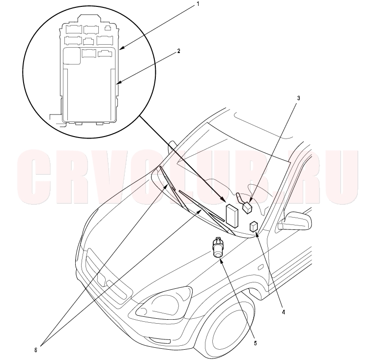
Component Location Index
NOTE: LHD type is shown, RHD type is similar.
Input Test, page 22A-242 Test, page 22A-240 ; Replacement, page 22A-240 Input Test, page 22A-244 Test, page 22A-248 ; Replacement, page 22A-250 Replacement, page 22A-250
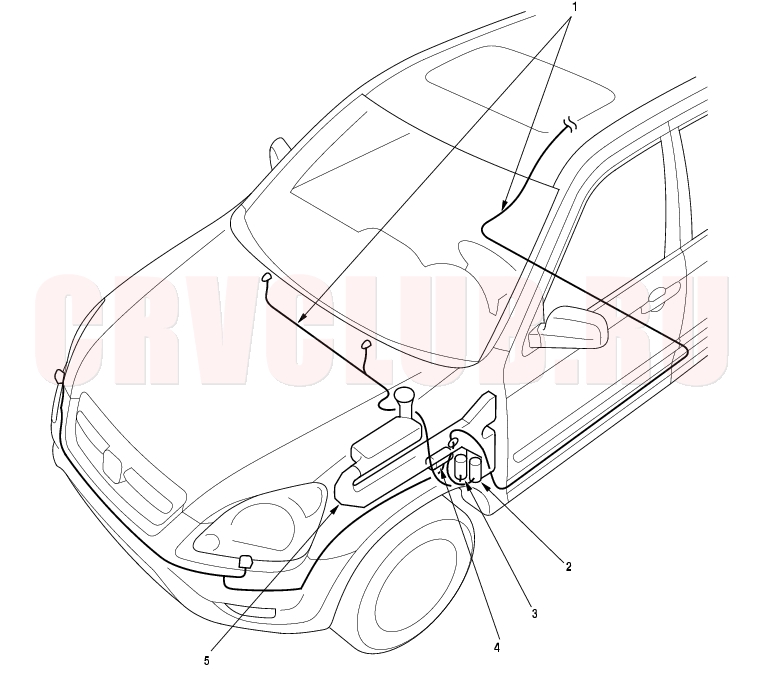
22A-207
NOTE: LHD type is shown, RHD type is similar.
Replacement, page 22A-254 Test, page 22A-239 Test, page 22A-239 Test, page 22A-239 Replacement, page 22A-253
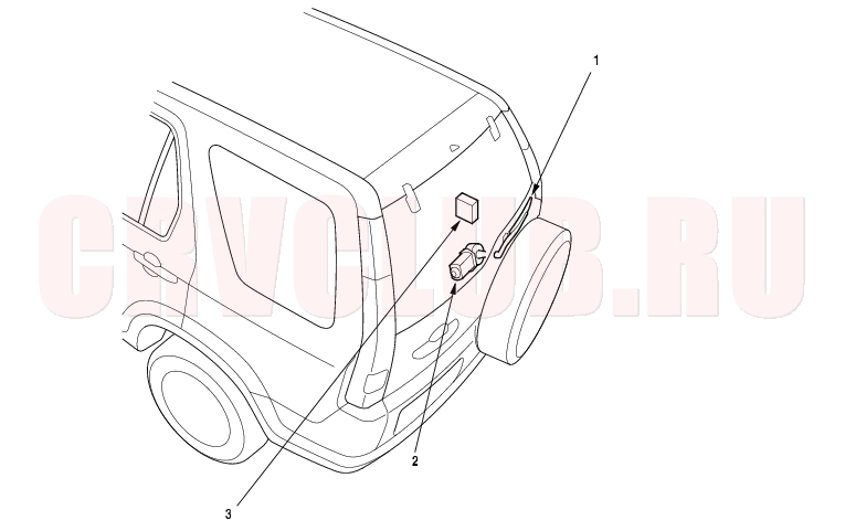
Component Location Index (cont'd) 22A-208
Replacement, page 22A-250 Test, page 22A-248 ; Replacement, page 22A-250 Input Test, page 22A-246
System Description 22A-209
Intermittent operation:
Rear window wiper switch ON: The wiper operates every seven seconds after completing two sweeps.
Rear window wiper switch OFF: The wiper returns to the park position.
Washer/Wiper combined system:
Rear window wiper switch ON: The wiper operates continuously while the washer switch is ON.
Rear window wiper switch OFF: After switching OFF the washer switch, the wiper returns to the park position after completing two sweeps.
Failsafe Function:
Lock Function: The rear window wiper will not operate if the hatch glass is open.
Emergency Stop Function: If the hatch glass is opened while the rear window wiper is operating, it will automatically stop.
Automatic Park Function: If the ignition switch is turned OFF while the rear window wiper is operating, the wiper will return to the park position.
NOTE: To avoid interference with the vehicle's spare tire, the rear wiper does not fold out as on previous models.
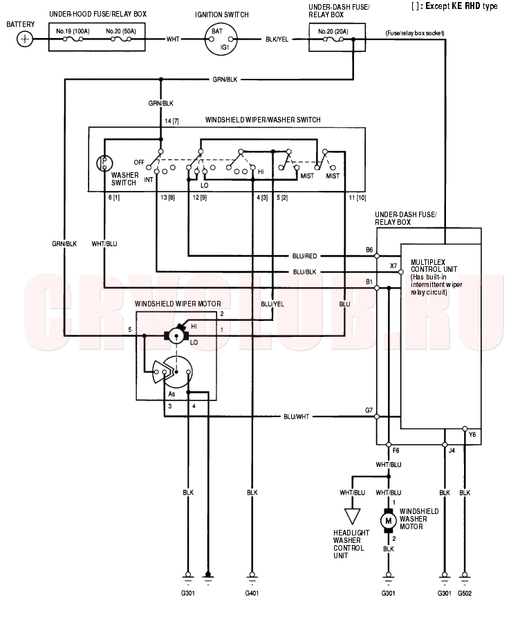
Circuit Diagram - Windshield 22A-210
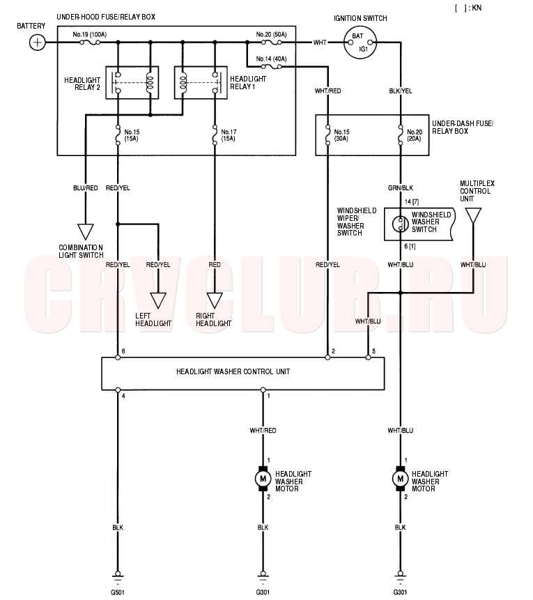
Circuit Diagram - Headlight Washer 22A-211
Circuit Diagram - Rear Window 22A-212
Washer Motor Test 22A-213
- Remove the left inner fender (see page 20-155) .
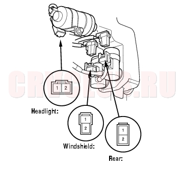
- Disconnect the 2P connector (A) from the washer motor (B).
- Test the motor by connecting battery power to the No. 1 terminal and ground the No. 2 terminal of the washer motor. The motor should run.
- If the motor does not run or fails to run smoothly, replace it.
- If the motor runs smoothly, but little or no washer fluid is pumped, check for a disconnected or blocked washer hose, or a clogged pump outlet in the motor.
Wiper/Washer Switch Test/Replacement 22A-214
- Remove the driver's dashboard lower cover (see page 20-88) .
- Remove the steering column covers (see page 17-24) .
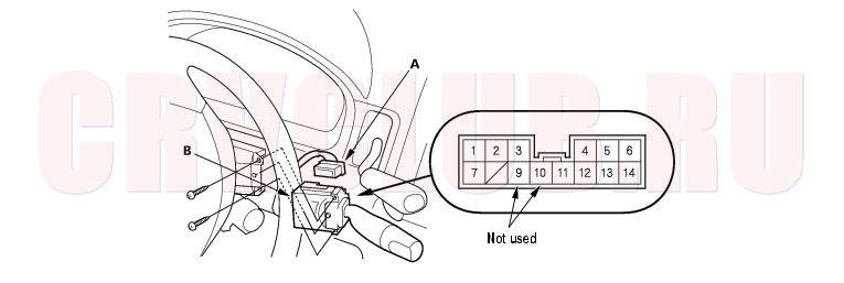
- Disconnect the 14P connector (A) from the wiper/washer switch (B).
LHD type and KE model:
RHD type:
22A-215
- Inspect the connector terminals to be sure they are all making good contact.
- If the terminals are bent, loose or corroded, repair them as necessary, and recheck the system.
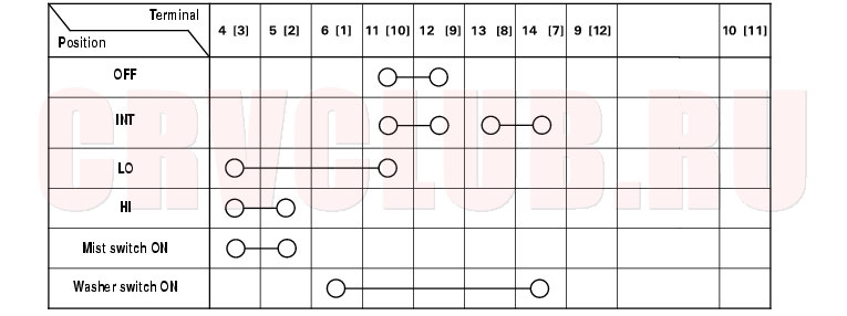
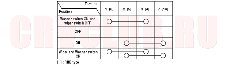
- If the terminals look OK, check for continuity between the terminals in each switch position according to the tables. If the continuity is not as specified, replace the switch.
Windshield:
Rear Window:
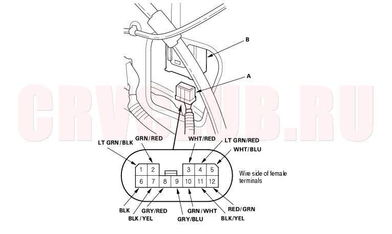
Control Unit Input Test 22A-216
- Before testing, troubleshoot the multiplex control system (see page 22A-261) .
- Remove the dashboard lower cover.
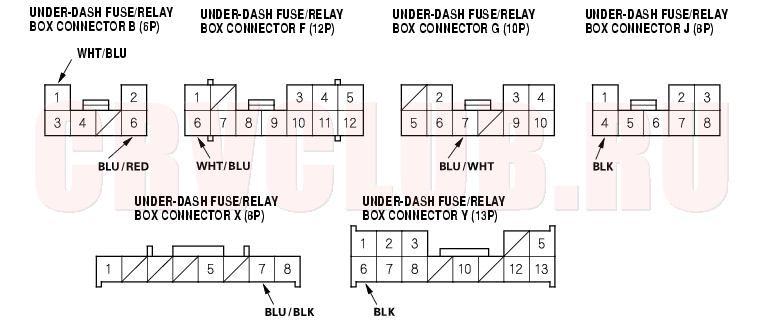
- Disconnect the under-dash fuse/relay box connectors B, F, G, J, X and Y.
- NOTE: All connectors are wire side of female terminals.
- Inspect the connector and socket terminals to be sure they are all making good contact.
- If the terminals are bent, loose or corroded, repair them as necessary, and recheck the system.
- If the terminals are OK, go to step 5.
22A-217
- Reconnect the connectors, and make these input tests at the connector.
- If any test indicates a problem, find and correct the cause, then recheck the system.
- If all the input tests prove OK, go to step 6.
- If all the input tests prove OK, the multiplex control unit must be faulty; replace the under-dash fuse/relay box assembly.
Headlight Washer Control Unit Input Test 22A-218
- Remove the dashboard lower cover.
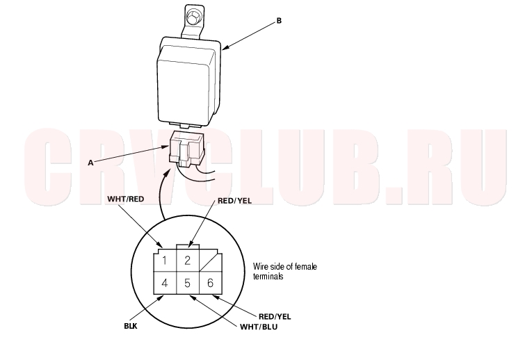
- Disconnect the 6P connector (A) from the headlight washer control unit (B).
- Inspect the connector and socket terminals to be sure they are all making good contact.
- If the terminals are bent, loose or corroded, repair them as necessary, and recheck the system.
- If the terminals look OK, go to step 4.
22A-219
- With the connector still disconnected, make these input tests at the connector.
- If any test indicates a problem, find and correct the cause, then recheck the system.
- If all the input tests prove OK, replace the headlight washer control unit.
Rear Wiper Control Unit Input Test 22A-220
- Remove the right rear side trim panel (see page 20-77) .
- Disconnect the 12P connector (A) from the control unit (B).
- Inspect the connector and socket terminals to be sure they are all making good contact.
- If the terminals are bent, loose or corroded, repair them as necessary, and recheck the system.
- If the terminals look OK, go to step 4.
- Reconnect the connector, and make these input tests at the connector.
- If any test indicates a problem, find and correct the cause, then recheck the system.
- If all the input tests prove OK, go to step 5.
22A-221
- Disconnect the connector, and make these input tests at the connector.
- If all the input tests prove OK, the control unit must be faulty; replace the rear wiper control unit.
Wiper Motor Test 22A-222
Windshield:
- Remove the wiper arms, hood seals, and cowl covers (see page 22A-250) .
- Disconnect the 5P connector (A) from the wiper motor (B).
- Test the motor by connecting battery power to the No. 5 terminal and ground the No. 1 terminal of the wiper motor 5P connector. The motor should run. If the motor does not run or fails to run smoothly, replace the motor.
- Connect an analog voltmeter between the No. 3 (+) and No. 4 (-) terminals, and run the motor at low or high speed. The voltmeter should indicate 12 V and 4 V or less alternately.
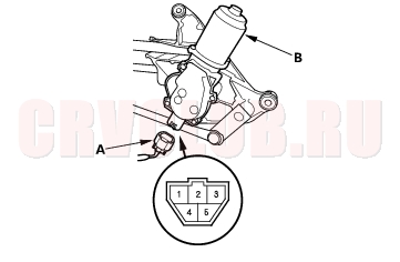
Rear Window:
- Open the tailgate, and remove the tailgate lower trim panel (see page 20-9) .
- Disconnect the 4P connector (A) from the wiper motor (B).
- Test the motor by connecting battery power to the No. 2 terminal and ground the No. 1 terminal of the wiper motor. The motor should run. If the motor does not run or fails to run smoothly, replace the motor.
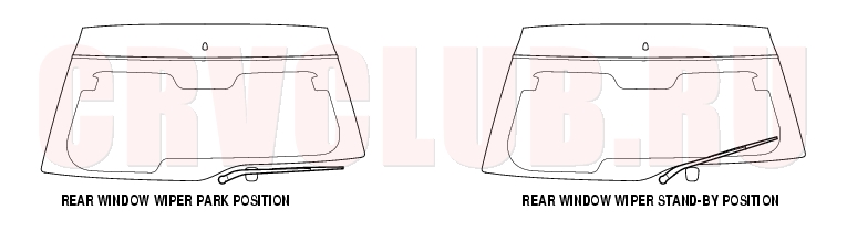
- Connect an ohmmeter between No. 3 and No. 6 terminal and between No. 3 terminal and No. 4 terminal.
- There should be continuity when the wiper is in the park position.
- Connect an ohmmeter between No. 3 terminal and No. 6 terminal.
- There should be no continuity when the wiper is in the stand-by position.
- Connect an ohmmeter between No.3 terminal and No. 4 terminal.
- There should be continuity when the wiper is in the stand-by position.
Wiper Motor Replacement 22A-223
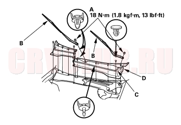
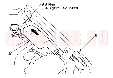
Windshield Wiper Motor:
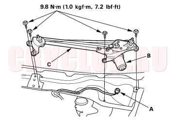
- Open the hood. Remove the nuts (A) and the windshield wiper arms (B).
- Remove the hood seals (C) and cowl covers (D).
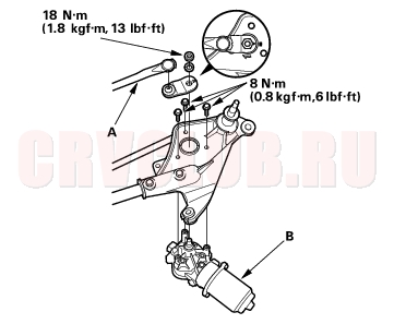
- Disconnect the 5P connector (A) from the wiper motor (B).
- Remove the four bolts and wiper linkage assembly (C).
- Remove the three mounting bolts and nut from the wiper linkage (A) to remove the wiper motor (B).
- Install in the reverse order of removal, and note these items:
- Grease the moving parts.
- Before reinstalling the wiper arms, turn the wiper switch ON, then OFF to return the wiper shafts to the park position.
- If necessary, replace any damaged clips.
- Check the wiper motor operation.
Wiper Motor Replacement (cont'd) 22A-224
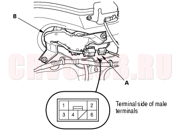
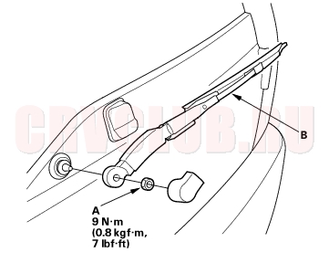
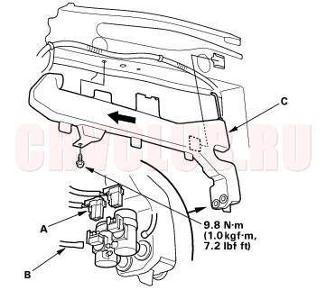
Rear Window Wiper Motor:
- Remove the mounting nut (A) and the wiper arm (B).
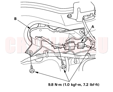
- Disconnect the 6P connector (A) from the wiper motor (B).
- Remove the three bolts and the wiper motor.
- Install in the reverse order of removal.
Check the wiper motor operation.
Washer Reservoir Replacement 22A-224
- Open the hood.
- Remove the bolt, then separate and remove the filler neck (A) from the washer reservoir (B).
- Remove the left inner fender (see page 20-155) .
- Disconnect the 2P connectors (A) and washer tubes (B).
- Remove the bolt and washer reservoir (C).
- Install the reservoir in the reverse order of removal. Check the the washer motor operation.
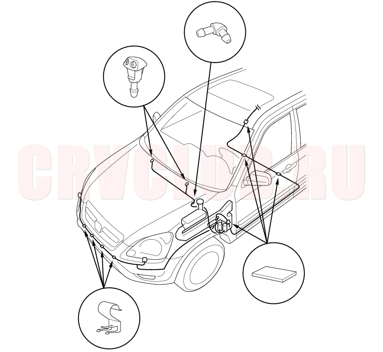
Washer Tubes Replacement 22A-225
- Remove the left inner fender (see page 20-155) .
- Remove the windshield washer nozzles and clips, then remove the tubes.
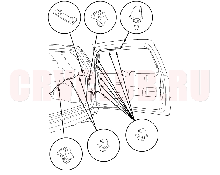
Washer Tubes Replacement (cont'd) 22A-226
|
Body Electrical22A-1
Wipers/Washers 22A-206 |