Engine Lubrication08-2
|
Engine Mechanical08-1
Engine Lubrication08-2 |
Engine Lubrication08-2
Special Tools
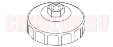
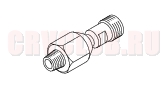
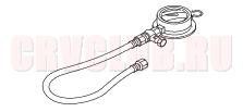
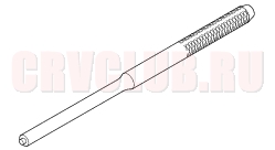
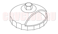
07HAA-PJ70100 Oil Filter Wrench 1 07406-0030000 Oil Pressure Gauge Attachment 1 07506-3000001 Oil Pressure Gauge 1 07744-0010500 Pin Driver, 6.0 mm 1 07912-6110001 Oil Filter Wrench 1
Component Location Index08-3
Removal, page 07-11 ; Installation, page 07-27 Overhaul, page 08-10 Replacement, page 08-9 Replacement, page 08-6 Circuit Diagram, page 22A-68 ; Switch Test, page 08-4 ; Oil Pressure test, page 08-4 ; Replacement, page 08-18
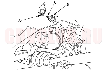
Oil Pressure Switch Test08-4
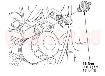
- Remove the YEL/RED wire (A) from the engine oil pressure switch (B).
- Check for continuity between the positive terminal (C) and the engine (ground). There should be continuity with the engine stopped. There should be no continuity with the engine running.
- If the switch fails to operate, check the engine oil level. If the engine oil level is OK, check the engine oil pressure. If the oil pressure is OK, replace the oil pressure switch.
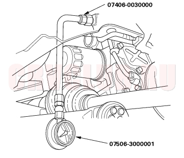
Oil Pressure Test08-4
Special Tools Required
Oil pressure gauge attachment 07406-0030000 Oil pressure gauge 07506-3000001 If the oil pressure warning light stays on with the engine running, check the engine oil level. If the oil level is correct:
- Connect a tachometer or a Honda PGM Tester.
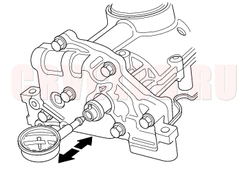
- Remove the engine oil pressure switch, and install an the special tools.
- Start the engine. Shut it off immediately if the gauge registers no oil pressure. Repair the problem before continuing.
- Allow the engine to reach operating temperature (fan comes on at least twice). The pressure should be:
Engine Oil Temperature: 80°C (176°F)
Engine Oil Pressure:
At Idle: 70 kPa (0.7 kgf/cm2, 10 psi)
minimum
At 3,000 rpm 340 kPa (3.5 kgf/cm2, 50 psi)
(min-1): minimum
- If the oil pressure is NOT within specifications, inspect these items.
- Check the oil screen for clogging.
- Check the oil pump (see page 08-12) .
Engine Oil Replacement08-5
- Warm up the engine.
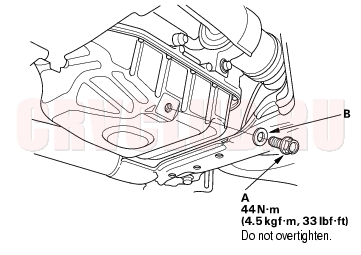
- Remove the drain bolt (A), and drain the engine oil.
- Reinstall the drain bolt with a new washer (B).
- Refill with the recommended oil (see page 03-2) .
Capacity
4.0 l (4.2 US qt, 3.5 lmp qt) at oil change.
4.2 l (4.4 US qt, 3.7 lmp qt) at oil change
including filter.
5.3 l (5.6 US qt, 4.7 lmp qt) after engine overhaul.
Engine Oil Filter Replacement08-6
Special Tools Required
Oil filter wrench 07HAA-PJ70100 Oil filter wrench 07912-6110001 JAPAN-MADE Engine Oil Filter
(3/4 - turn type)
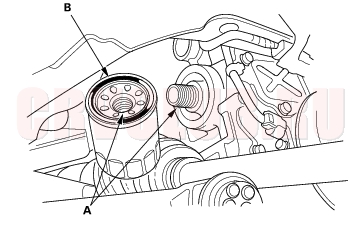
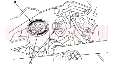
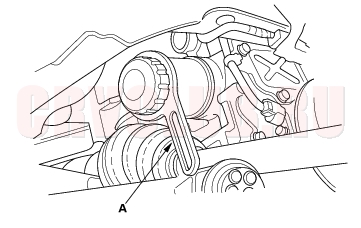
- Remove the oil filter with the special oil filter wrench.
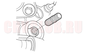
- Inspect the threads (A) and rubber seal (B) on the new filter. Wipe off the seat on the engine block, then apply a light coat of oil to the filter rubber seal. Use only filters with a built-in bypass system.
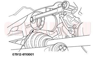
- Install the oil filter by hand.
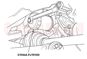
- After the rubber seal seats, tighten the oil filter clockwise with the special tool.
Tighten: 3/4 turn clockwise.
Tightening torque: 12 N·m (1.2 kgf·m, 8.7 lbf·ft)
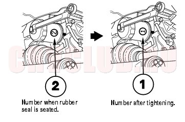
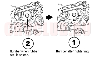
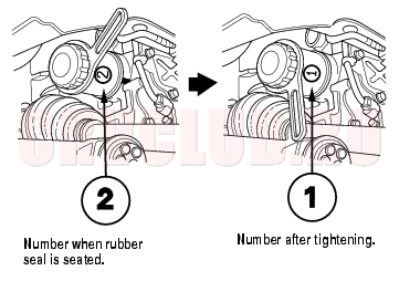
- If 4 numbers or marks (1 to 4 or
to


) are printed around the outside of the filter, use the following procedure to tighten the filter.
- Spin the filter on until its seal lightly seats against the block, and note which number or mark is at the bottom.
- Tighten the filter by turning it clockwise 3 numbers or marks from the one you noted. For example, if number 2 is at the bottom when the seal is seated, tighten the filter until the number 1 comes around the bottom.
- After installation, fill the engine with oil up to the specified level, run the engine for more than 3 minutes, then check for oil leakage.
08-7
JAPAN-MADE Engine Oil Filter
(7/8 - turn type)
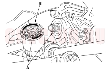
- Remove the oil filter with the special oil filter wrench.
- Inspect the threads (A) and rubber seal (B) on the new filter. Wipe off the seat on the engine block, then apply a light coat of oil to the filter rubber seal. Use only filters with a built-in bypass system.
- Install the oil filter by hand.
- After the rubber seal seats, tighten the oil filter clockwise with the special tool.
Tighten: 7/8 turn clockwise.
Tightening torque: 22 N·m (2.2 kgf·m, 16 lbf·ft)
- If 8 numbers (1 to 8) are printed around the outside of the filter, use the following procedure to tighten the filter.
- Spin the filter on until its seal lightly seats against the block, and note which number is at the bottom.
- Tighten the filter by turning it clockwise 7 numbers from the one you noted. For example, if number 2 is at the bottom when the seal is seated, tighten the filter until the number 1 comes around the bottom.
- After installation, fill the engine with oil up to the specified level, run the engine for more than 3 minutes, then check for oil leakage.
Engine Oil Filter Replacement (cont'd)08-8
FRANCE-MADE Engine Oil Filter
(3/4 - turn type)
- Remove the oil filter with the commercially available oil filter wrench (LABINAL-Purflux 76).
- Inspect the threads (A) and rubber seal (B) on the new filter. Wipe off the seat on the engine block, then apply a light coat of oil to the filter rubber seal. Use only filters with a built-in bypass system.
- Install the oil filter by hand.
- After the rubber seal seats, tighten the oil filter clockwise with the commercially available oil filter wrench (LABINAL-Purflux 76)(A).
Tighten: 3/4 turn clockwise.
Tightening torque: 22 N·m (2.2 kgf·m, 16 lbf·ft)
- If 4 numbers (1 to 4) are printed around the outside of the filter, use the following procedure to tighten the filter.
- Spin the filter on until its seal lightly seats against the block, and note which number is at the bottom.
- Tighten the filter by turning it clockwise 3 numbers from the one you noted. For example, if number 2 is at the bottom when the seal is seated, tighten the filter until the number 1 comes around the bottom.
- After installation, fill the engine with oil up to the specified level, run the engine for more than 3 minutes, then check for oil leakage.
Oil Filter Holder Replacement08-9
- Remove the oil filter (see page 08-6) .
- Remove the oil filter holder.
- Tighten the new oil filter holder to 49 N·m (5.0 kgf·m, 36 lbf·ft)
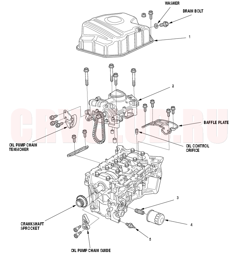
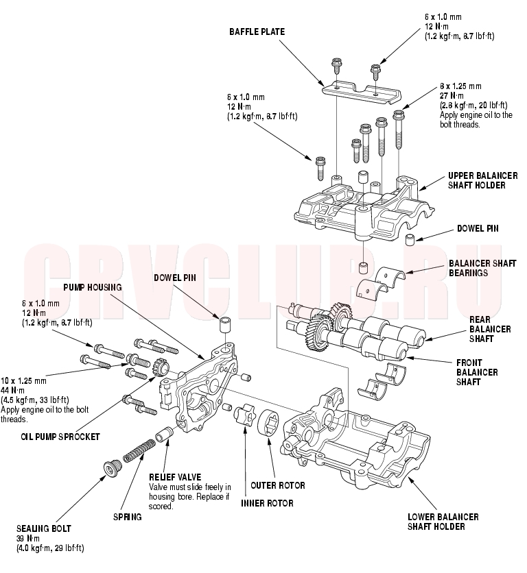
Oil Pump Overhaul08-10
Exploded View
08-11
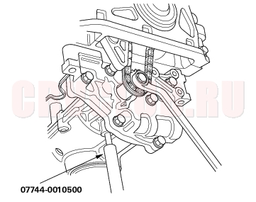
Special Tools Required
Pin driver, 6.0 mm 07744-0010500
Oil Pump Removal
- Set the No. 1 piston at Top Dead Center (TDC) (see step 1 on page 06-12 ).
- Remove the oil pan (see page 07-11) .
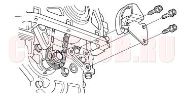
- Remove the oil pump chain tensioner.
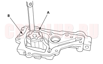
- To hold the rear balancer shaft, insert a pin driver into the hole in the rear balancer shaft, through the maintenance hole on the lower balancer shaft holder.
- Loosen the oil pump sprocket mounting bolt.
- Remove the oil pump sprocket (A), then remove the oil pump (B).
Oil Pump Overhaul (cont'd)08-12
Oil Pump Inspection
- Remove the pump housing.
- Check the inner-to-outer rotor radial clearance between the inner rotor (A) and outer rotor (B). If the inner-to-outer rotor radial clearance exceeds the service limit, replace the oil pump.
Inner Rotor-to-Outer Rotor Radial Clearance
Standard (New): 0.02 - 0.16 mm (0.001 - 0.006 in.)
Service Limit: 0.20 mm (0.008 in.)
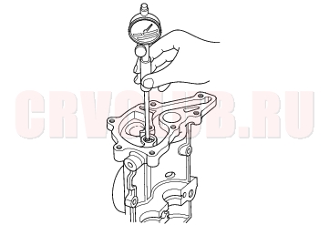
- Check the housing-to-rotor axial clearance between the rotor (A) and pump housing (B). If the housing-to-rotor axial clearance exceeds the service limit, replace the oil pump.
Housing-to-Rotor Axial Clearance
Standard (New): 0.02 - 0.07 mm (0.001 - 0.003 in.)
Service Limit: 0.12 mm (0.005 in.)
- Check the housing-to-outer rotor radial clearance between the outer rotor (A) and pump housing (B). If the housing-to-outer rotor radial clearance exceeds the service limit, replace the oil pump.
Housing-to-Outer Rotor Radial Clearance
Standard (New): 0.15 - 0.21 mm (0.006 - 0.008 in.)
Service Limit: 0.23 mm (0.009 in.)
08-13
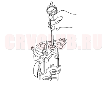
Balancer Shaft Inspection
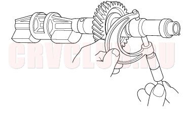
- Seat the balancer shaft by pushing it away from the oil pump sprocket end of the oil pump.
- Zero the dial indicator against the end of the balancer shaft, then push the balancer shaft back and forth and read the end play.
Balancer Shaft End Play:
Front Balancer Shaft:
Standard (New): 0.070 - 0.135 mm
(0.0028 - 0.0053 in.)
Service Limit: 0.15 mm (0.006 in.)
Rear Balancer Shaft:
Standard (New): 0.070 - 0.135 mm
(0.0028 - 0.0053 in.)
Service Limit: 0.15 mm (0.006 in.)
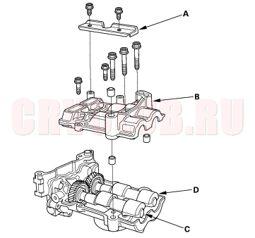
- Remove the baffle plate (A) and upper balancer shaft holder (B), then remove the front balancer shaft (C) and rear balancer shaft (D).
Oil Pump Overhaul (cont'd)08-14
- Measure the inner diameter of the No. 1 bearing for the front balancer shaft hole and the rear balancer shaft hole.
Bearing Inner Diameter:
Front:
Standard (New): 20.000 - 20.020 mm
(0.7874 - 0.7882 in.)
Service Limit: 20.03 mm (0.789 in.)
Rear:
Standard (New): 24.000 - 24.020 mm
(0.9449 - 0.9457 in.)
Service Limit: 24.03 mm (0.946 in.)
Journal Diameter:
Front:
Standard (New): 19.938 - 19.950 mm
(0.7850 - 0.7854 in.)
Service Limit: 19.92 mm (0.784 in.)
Rear:
Standard (New): 23.938 - 23.950 mm
(0.9424 - 0.9429 in.)
Service Limit: 23.92 mm (0.942 in.)
08-15
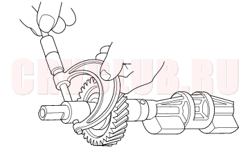
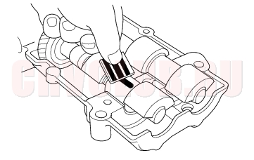
- Clean each balancer shaft No. 2 journals and bearings half with a clean shop towel.
- Place one strip of plastigage across each journal.
- Reinstall the bearings and upper balancer shaft holder, the torque the bolts.
- NOTE: Do not rotate the balancer shaft during inspection.
- Remove the upper balancer shaft holder and bearings again, and measure the widest part of the plastigage.
- If the balancer shaft No. 2 journal oil clearance is out-of-tolerance, install the new bearings, and recheck. If it is still out-of-tolerance; replace the balancer shafts.
No. 2 Journal Oil Clearance:
Standard (New): 0.060 - 0.120 mm
(0.0024 - 0.0047 in.)
Service Limit: 0.15 mm (0.006 in.)
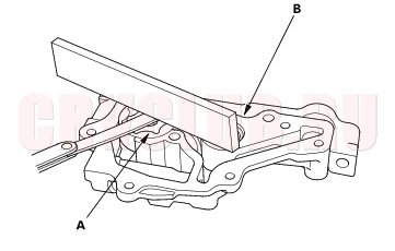
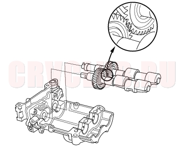
- Align the punch mark on the rear balancer shaft with the center of the two punch marks on the front balancer shaft, then install the balancer shafts on the lower balancer shaft holder.
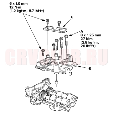
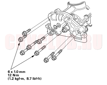
- Apply engine oil to the threads of the 8 mm bolts (A).
- Install the upper balancer shaft holder (B) and baffle plate (C).
Oil Pump Overhaul (cont'd)08-16
Oil Pump Installation
- Check the No. 1 piston at TDC (see step 1 on page 06-12 ).
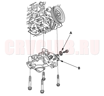
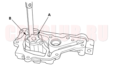
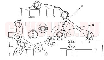
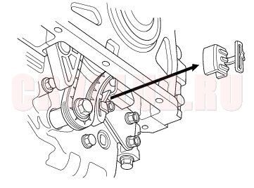
- Align the dowel pin (A) on the rear balancer shaft with the mark (B) on the oil pump.
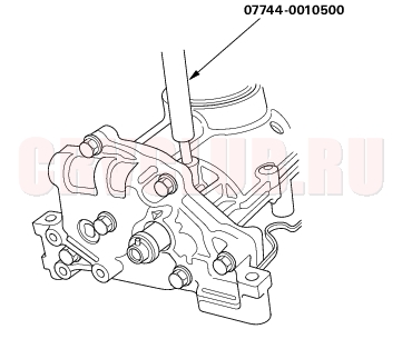
- To hold the rear balancer shaft, insert a pin driver into the hole in the rear balancer shaft, through the maintenance hole on the lower balancer shaft holder.
08-17
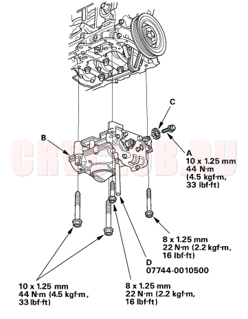
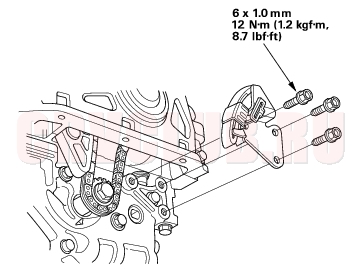
- Apply engine oil to the threads of the oil pump sprocket mounting bolt (A).
- Loosely install the oil pump (B), then install the oil pump sprocket (C).
- Remove the pin driver (D).
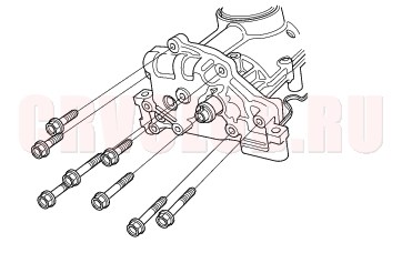
- Tighten the oil pump mounting bolts.
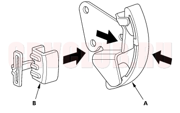
- Squeeze the new oil pump chain tensioner (A), then install the set clip (B) on it as shown.
- NOTE: The set clip is supplied with the oil pump chain tensioner.
- Install the oil pump chain tensioner.
Oil Pump Overhaul (cont'd)08-18
- Remove the set clip from the oil pump chain tensioner.
- Install the oil pan (see page 07-27) .
Oil Pressure Switch Replacement08-18
|
Engine Mechanical08-1
Engine Lubrication08-2 |