Engine Block07-2
|
Engine Mechanical07-1
Engine Block07-2 |
Engine Block07-2
Special Tools
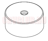
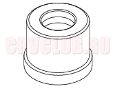
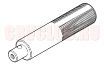
07ZAD-PNA0100 Oil Seal Driver Attachment 96 07746-0010700 Driver Attachment, 24 x 26 mm 07749-0010000 Handle Driver
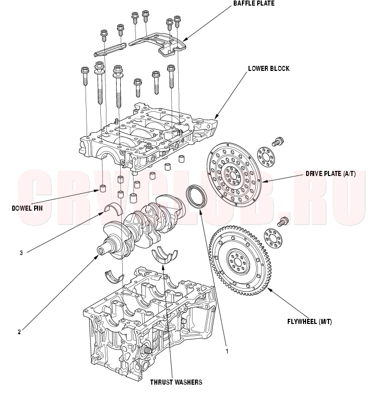
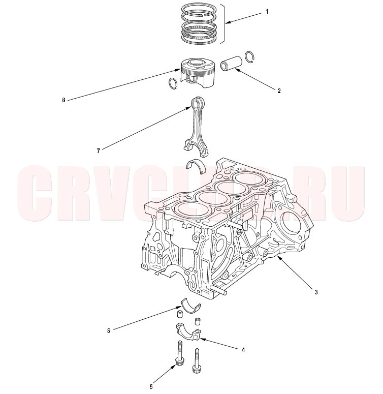
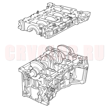
Component Location Index07-3
Installation, step 21 on page 07-26 End play, page 07-5 ; Runout, page 07-14 ; Out-of-Round, page 07-14 ; Removal, page 07-12 ; Installation, page 07-24 Oil clearance, page 07-6 ; Selection, page 07-6
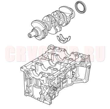
Component Location Index (cont'd)07-4
Replacement, page 07-21 Removal, page 07-18 ; Inspection, page 07-19 ; Installation, page 07-20 Cylinder bore inspection, page 07-15 ; Warpage inspection, page 07-15 ; Cylinder bore honing, page 07-17 ; Ridge removal, step 13 on page 07-13 Inspection, page 07-24 Oil clearance, page 07-8 ; Selection, page 07-9 End play, page 07-5 ; Small end measurement, page 07-19 Removal, page 07-12 ; Measurement, page 07-15
Connecting Rod and Crankshaft End Play Inspection07-5
- Remove the oil pump (see page 08-11) .
- Remove the baffle plate (see step 6 on page 07-12 ).
- Measure the connecting rod end play with a feeler gauge between the connecting rod and crankshaft.
Connecting Rod End Play:
Standard (New): 0.15 - 0.30 mm
(0.006 - 0.012 in.)
Service Limit: 0.40 mm (0.016 in.)
- If the connecting rod end play is out-of-tolerance, install a new connecting rod, and recheck. If it is still out-of-tolerance; replace the crankshaft (see page 07-12) .
- Push the crankshaft firmly away from the dial indicator, and zero the dial against the end of the crankshaft. Then pull the crankshaft firmly back toward the indicator; the dial reading should not exceed the service limit.
Crankshaft End Play:
Standard (New): 0.10 - 0.35 mm
(0.004 - 0.014 in.)
Service Limit: 0.45 mm (0.018 in.)
- If the end play is out-of-tolerance, replace the thrust washers and recheck, if it is still out-of-tolerance, replace the crankshaft.
Crankshaft Main Bearing Replacement07-6
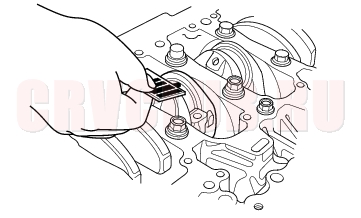
Main Bearing Clearance Inspection
- To check main bearing-to-journal oil clearance, remove the lower block and bearing halves (see page 07-12) .
- Clean each main journal and bearing half with a clean shop towel.
- Place one strip of plastigage across each main journal.
- Reinstall the bearings and lower block, then torque the bolts to 29 N·m (3.0 kgf·m, 22 lbf·ft) + 56°.
- NOTE: Do not rotate the crankshaft during inspection.
- Remove the lower block and bearings again, and measure the widest part of the plastigage.
Main Bearing-to-Journal Oil Clearance:
No. 1, 2, 4, 5 Journals:
Standard (New): 0.017 - 0.041 mm
(0.0007 - 0.0016 in.)
Service Limit: 0.050 mm (0.0020 in.)
No. 3 Journal:
Standard (New): 0.025 - 0.049 mm
(0.0010 - 0.0019 in.)
Service Limit: 0.055 mm (0.0022 in.)
- If the plastigage measures too wide or too narrow, remove the crankshaft, and remove the upper half of the bearing. Install a new, complete bearing with the same color code(s), and recheck the clearance. Do not file, shim, or scrape the bearings or the caps to adjust clearance.
- If the plastigage shows the clearance is still incorrect, try the next larger or smaller bearing (the color listed above or below that one), and check again. If the proper clearance cannot be obtained by using the appropriate larger or smaller bearings, replace the crankshaft and start over.
07-7
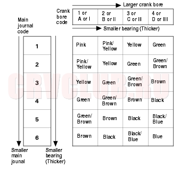
Main Bearing Selection
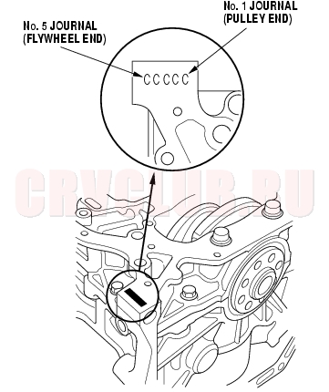
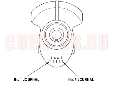
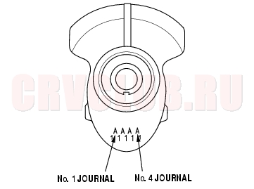
Crankshaft Bore Code Location
- Numbers or letters or bars have been stamped on the end of the block as a code for the size of each of the five main journal bores. Write down the crank bore codes.
If you can't read the codes because of accumulated dirt and dust, do not scrub them with a wire brush or scraper. Clean them only with solvent or detergent.
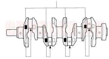
Main Journal Code Location
Crankshaft Main Bearing Replacement (cont'd)07-8
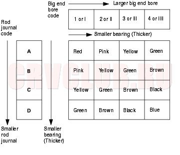
- Use the crank bore codes and crank journal codes to select the appropriate replacement bearings from the following table.
- NOTE:
- Color code is on the edge of the bearing.
- When using bearing halves of different colors, it does not matter which color is used in the top or bottom.
Connecting Rod Bearing Replacement07-8
Rod Bearing Clearance Inspection
- Remove the oil pump (see page 08-11) .
- Remove the baffle plate (see step 6 on page 07-12 ).
- Remove the connecting rod cap and bearing half.
- Clean the crankshaft rod journal and bearing half with a clean shop towel.
- Place plastigage across the rod journal.
- Reinstall the bearing half and cap, and torque the bolts to 20 N·m (2.0 kgf·m, 14 lbf·ft) + 90°.
- NOTE: Do not rotate the crankshaft during inspection.
- Remove the rod cap and bearing half, and measure the widest part of the plastigage.
Connecting Rod Bearing-to-Journal Oil Clearance:
Standard (New): 0.021 - 0.049 mm
(0.0008 - 0.0019 in.)
Service Limit: 0.060 mm (0.0024 in.)
07-9
- If the plastigage measures too wide or too narrow, remove the upper half of the bearing, install a new, complete bearing with the same color code(s), and recheck the clearance. Do not file, shim, or scrape the bearings or the caps to adjust clearance.
- If the plastigage shows the clearance is still incorrect, try the next larger or smaller bearing (the color listed above or below that one), and check clearance again. If the proper clearance cannot be obtained by using the appropriate larger or smaller bearing, replace the crankshaft and start over.
Rod Bearing Selection
Connecting Rod Big End Bore Code Locations
- Each rod has a tolerance range from 0 to 0.024 mm (0.0009 in.), in 0.006 mm (0.0002 in.) increments, depending on the size of its big end bore. It's then stamped with a number or bar (1, 2, 3 or 4/l, ll, lll, or llll) indicating the range. You may find any combination of numbers and bars in any engine, (Half the number or bar is stamped on the bearing cap, the other half on the rod.).
- If you can't read the code because of an accumulation of oil and varnish, do not scrub it with a wire brush or scraper. Clean it only with solvent or detergent.
Normal Bore Size:
K20A4, K20A5 engines: 48.0 mm (1.89 in.)
K24A1 engine: 51.0 mm (2.01 in.)
Connecting Rod Bearing Replacement (cont'd)07-10
Connecting Rod Journal Code Location
Connecting Rod Journal Code Location (Letters or Bars)
- Use the big end bore codes and rod journal codes to select appropriate replacement bearings from the following table.
- NOTE: Color code is on the edge of the bearing.
Oil Pan Removal07-11
- If the engine is still in the vehicle, remove the sub-frame.
- Drain the engine oil (see page 08-5) .
- Attach the chain hoist to the engine (see step 38 on page 05-7 ).
- Disconnect the suspension lower arm ball joints (see page 18-20) .
- Remove the rear mount mounting bolts (see step 42 on page 05-8 ).
- Remove the front mount mounting bolt (see step 43 on page 05-9 ).
- Remove the ATF filter mounting bolt (A/T) (see step 34 on page 05-7 ).
- Use a marker to make alignment marks on the reference lines that align with the centers of the rear sub-frame mounting bolts. Remove the front sub-frame (see step 44 on page 05-9 ).
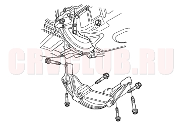
- Remove the stiffener (K24A1 engine M/T).
- Remove the bolts/nuts securing the oil pan.
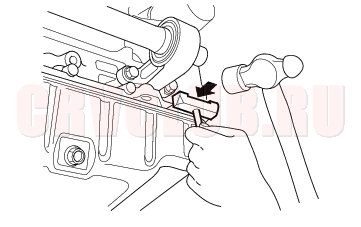
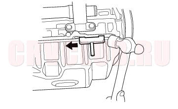
- Drive an oil pan seal cutter between the oil pan and cylinder block.
- Cut the oil pan seal by striking the side of the cutter to slide the cutter along the oil pan.
- Remove the oil pan.
Crankshaft and Piston Removal07-12
- Remove the engine assembly (see page 05-3) .
- Remove the transmission:
- Manual transmission (see page 13-5) .
- Automatic transmission (see page 14-135) .
- Remove the oil pan (see page 07-11) .
- Remove the oil pump (see page 08-11) .
- Remove the cylinder head (see page 06-24) .
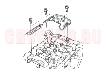
- Remove the baffle plates.
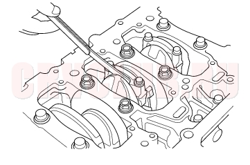
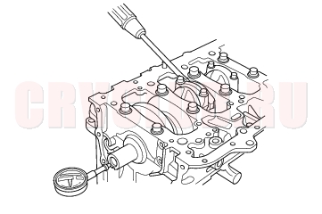
- Remove the 8 mm bolts.
- Remove the bearing cap bolts. To prevent warpage, unscrew the bolts in sequence 1/3 turn at a time: repeat the sequence until all bolts are loosened.
- Remove the lower block and bearings. Keep all bearings in order.
07-13
- Remove the rod caps/bearings. Keep all caps/bearings in order.
- Lift the crankshaft out of the engine, being careful not to damage the journals.
- Remove the upper bearing halves from the connecting rods, and set them aside with their respective caps.
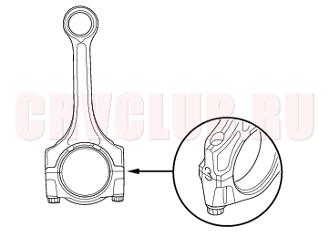
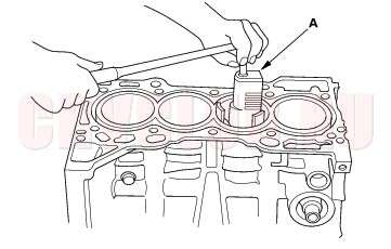
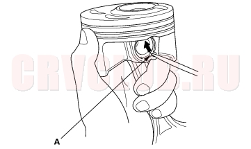
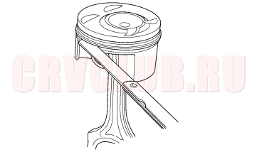
- If you can feel a ridge of metal or hard carbon around the top of each cylinder, remove it with a ridge reamer (A). Follow the reamer manufacturer's instructions. If the ridge is not removed, it may damage the pistons as they are pushed out.
- Use the wooden handle of a hammer (A) to drive out the pistons (B).
- Reinstall the lower block and bearings on the engine in the proper order.
- Reinstall the connecting rod bearings and caps after removing each piston/connecting rod assembly.
- To avoid mixup on reassembly, mark each piston/connecting rod assembly with its cylinder number.
- NOTE: The existing number on the connecting rod does not indicate its position in the engine, it indicates the rod bore size.
Crankshaft Inspection07-14
Out-of-Round and Taper
- Remove the crankshaft from the cylinder block (see page 07-12) .
- Clean the crankshaft oil passages with pipe cleaners or suitable brush.
- Clean the keyway and threads.
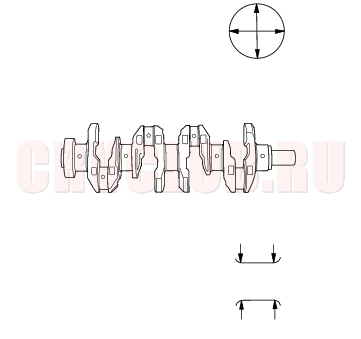
- Measure out-of-round at the middle of each rod and main journal in two places. The difference between measurements on each journal must not be more than the service limit.
Journal Out-of-Round:
Standard (New): 0.005 mm (0.0002 in.) max.
Service Limit: 0.010 mm (0.0004 in.)
- Measure taper at the edges of each rod and main journal. The difference between measurement on each journal must not be more than the service limit.
Journal Taper:
Standard (New): 0.005 mm (0.0002 in.) max.
Service Limit: 0.010 mm (0.0004 in.)
Straightness
- Place the cylinder block on the surface plate.
- Clean and install the bearings on the No. 1 and
No. 5 journal of the cylinder block.
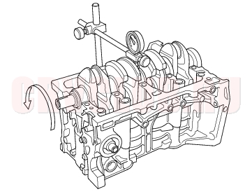
- Lower the crankshaft into the block.
- Measure runout on all main journals. Rotate the crankshaft two complete revolutions. The difference between measurements on each journal must not be more than the service limit.
Crankshaft Total Runout:
Standard (New): 0.03 mm (0.0012 in.) max.
Service Limit: 0.04 mm (0.0016 in.)
Block and Piston Inspection07-15
- Remove the crankshaft and pistons (see page 07-12) .
- Check the piston for distortion or cracks.
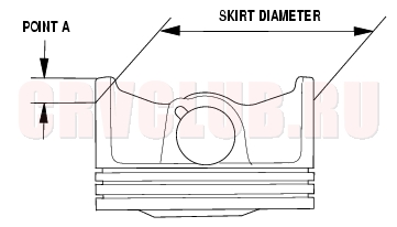
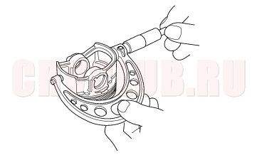
- Measure the piston diameter at a point A from the bottom of the skirt. There are two standard-size pistons (No Letter or A, and B). The letter is stamped on the top of the piston. Letters are also stamped on the block as cylinder bore sizes.
Point A:
K20A4, K20A5
engines: 11 mm (0.4 in.)
K24A1 engine: 13 mm (0.5 in.)
Piston Diameter:
Standard (New):
K20A4, K20A5 engines:
No Letter (or A): 85.980 - 85.990 mm
(3.3850 - 3.3854 in.)
B: 85.970 - 85.980 mm
(3.3846 - 3.3850 in.)
K24A1, engine:
No Letter (or A): 86.980 - 86.990 mm
(3.4244 - 3.4248 in.)
B: 86.970 - 86.980 mm
(3.4240 - 3.4244 in.)
Service Limit:
K20A4, K20A5 engines:
No Letter (or A): 85.930 mm (3.3831 in.)
B: 85.920 mm (3.3827 in.)
K24A1 engine:
No Letter (or A): 86.930 mm (3.4224 in.)
B: 86.920 mm (3.4220 in.)
Oversize Piston Diameter:
K20A4, K20A5 engines:
0.25: 86.230 - 86.240 mm (3.3949 - 3.3953 in.)
K24A1 engine:
0.25: 87.230 - 87.240 mm (3.4342 - 3.4346 in.)
Block and Piston Inspection (cont'd)07-16
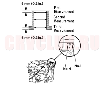
- Measure wear and taper in direction X and Y at three levels in each cylinder as shown. If measurements in any cylinder are beyond the Oversize Bore Service Limit, replace the block. If the block is to be rebored, refer to step 7 after reboring.
Cylinder Bore Size:
K20A4, K20A5 engines:
Standard (New):
A or I: 86.010 - 86.020 mm
(3.3862 - 3.3866 in.)
B or II: 86.000 - 86.010 mm
(3.3858 - 3.3862 in.)
Service Limit: 86.070 mm (3.3886 in.)
K24A1 engine:
Standard (New):
A or I: 87.010-87.020 mm
(3.4256-3.4260 in.)
B or II: 87.000-87.010 mm
(3.4252-3.4256 in.)
Service Limit: 87.070 mm (3.4279 in.)
Oversize:
K20A4, K20A5 engines:
0.25: 86.250 - 86.260 mm (3.3957 - 3.3961 in.)
K24A1 engine:
0.25: 87.250-87.260 mm (3.4350-3.4354 in.)
Reboring limit: 0.25 mm (0.01 in.) max.
Bore Taper:
Limit: (Difference between first and third measurement) 0.05 mm (0.002 in.)
- Scored or scratched cylinder bores must be honed.
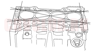
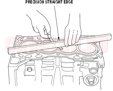
- Check the top of the block for warpage. Measure along the edges and across the center as shown.
Engine Block Warpage:
Standard (New): 0.07 mm (0.003 in.) max.
Service Limit: 0.10 mm (0.004 in.)
07-17
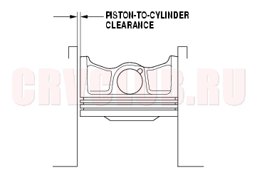
- Calculate the difference between the cylinder bore diameter and the piston diameter. If the clearance is near or exceeds the service limit, inspect the piston and cylinder block for excessive wear.
Piston-to-Cylinder Clearance:
Standard (New): 0.020 - 0.040 mm
(0.0008 - 0.0016 in.)
Service Limit: 0.05 mm (0.002 in.)
Cylinder Honing07-17
Only a scored or scratched cylinder bore must be honed.
- Measure the cylinder bores (see step 4 on page 07-16 ).
- If the block is to be reused, hone the cylinders and remeasure the bores.
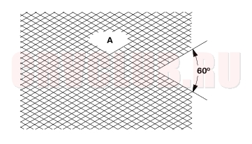
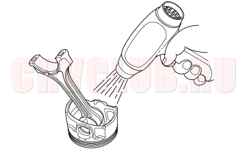
- Hone the cylinder bores with honing oil and a fine (400 grit) stone in a 60 degree cross-hatch pattern (A). Use only a rigid hone with 400 grit or finer stone such as Sunnen, Ammco, or equivalent. Do not use stones that are worn or broken.
- When honing is complete, thoroughly clean the engine block of all metal particles. Wash the cylinder bores with hot soapy water, then dry and oil them immediately to prevent rusting. Never use solvent, it will only redistribute the grit on the cylinder walls.
- If scoring or scratches are still present in the cylinder bores after honing to the service limit, rebore the cylinder block. Some light vertical scoring and scratching is acceptable if it is not deep enough to catch your fingernail and does not run the full length of the bore.
Piston, Pin and Connecting Rod Replacement07-18
Disassembly
- Remove the piston from the cylinder block (see page 07-12 ).
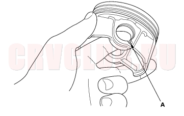
- Apply engine oil to the piston pin snap rings (A), and turn them in the ring grooves until the end gaps are lined up with the cutouts in the piston pin bores (B).
- NOTE: Take care not to damage the ring grooves.
- Remove both snap rings (A). Start at the cutout in the piston pin bore. Remove the snap rings carefully so they do not go flying or get lost. Wear eye protection.
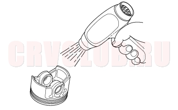
- Heat the piston and connecting rod assembly to about 70°C (158°F), then remove the piston pin.
07-19
Inspection
NOTE: Inspect the piston, piston pin, and connecting rod when they are at room temperature.
Piston Pin Diameter:
Standard (New): 21.961 - 21.965 mm
(0.8646 - 0.8648 in.)
Service Limit: 21.953 mm (0.8643 in.)
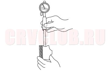
- Zero the dial indicator to the piston pin diameter.
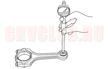
- Check the difference between the piston pin diameter and piston pin hole diameter in the piston.
Piston Pin-to-Piston Clearance:
Standard (New): - 0.005 to +0.002 mm
(- 0.00020 to +0.00008 in.)
Service Limit: 0.005 mm (0.0002 in.)
Piston Pin-to-Connecting Rod Clearance:
Standard (New): 0.005 - 0.015 mm
(0.0002 - 0.0006 in.)
Service Limit: 0.02 mm (0.0008 in.)
Piston, Pin and Connecting Rod Replacement (cont'd)07-20
Reassembly
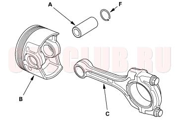
- Install a piston pin snap ring (A).
- Coat the piston pin bore in the piston, the bore in the connecting rod, and the piston pin with engine oil.
- Heat the piston to about 70°C (158°F).
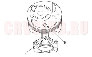
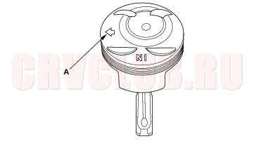
- Install the piston pin (A). Assemble the piston (B) and connecting rod (C) with the arrow (D) and the embossed mark (E) on the same side.
- Install the remaining snap ring (F).
- Turn the snap rings in the ring grooves until the end gaps are positioned at the bottom of the piston.
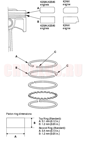
Piston Ring Replacement07-21
- Remove the piston from the cylinder block (see page 07-12) .
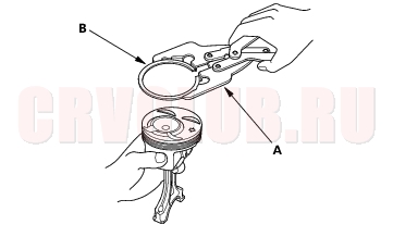
- Using a ring expander (A), remove the old piston rings (B).
- Clean all ring grooves thoroughly with a squared-off broken ring or ring groove cleaner with a blade to fit the piston grooves.
The top and 2nd ring grooves are 1.2 mm (0.05 in.) wide. The oil ring groove is 2.0 mm (0.08 in.) wide (K20A4, K24A1 engines) or 2.8 mm (0.11 in.) wide (K20A5 engine).
File down a blade if necessary.
Do not use a wire brush to clean the ring grooves, or cut the ring grooves deeper with the cleaning tools.
- NOTE: If the piston is to be separated from the connecting rod, do not install new rings yet.
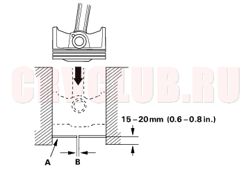
- Using a piston, push a new ring (A) into the cylinder bore 15 - 20 mm (0.6 - 0.8 in.) from the bottom.
- Measure the piston ring end-gap (B) with a feeler gauge:
- If the gap is too small, check to see if you have the proper rings for your engine.
- If the gap is too large, recheck the cylinder bore diameter against the wear limits (see step 4 on page 07-16 ).
If the bore is over the service limit, the cylinder block must be rebored.Piston Ring End-Gap:
Top Ring
Standard (New): 0.20 - 0.35 mm
(0.008 - 0.014 in.)
Service Limit: 0.60 mm (0.024 in.)
Second Ring
Standard (New): 0.40 - 0.55 mm
(0.016 - 0.022 in.)
Service Limit: 0.70 mm (0.028 in.)
Oil Ring
K20A4 (Except KY models) engine
Standard (New): 0.25 - 0.65 mm
(0.010 - 0.026 in.)
Service Limit: 0.75 mm (0.030 in.)
K20A4 (KY models), K20A5, K24A1 engines
Standard (New): 0.20 - 0.70 mm
(0.008 - 0.028 in.)
Service Limit: 0.80 mm (0.031 in.)
Piston Ring Replacement (cont'd)07-22
- Install the top ring and second ring as shown.The top ring (A) has a T or 1R mark and the second ring (B) has a 2T or 2R mark. The manufacturing marks (C) must be facing upward.
- Rotate the rings in their grooves to make sure they do not bind.
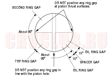
- Position the ring end gaps as shown:
- After installing a new set of rings, measure the ring-to-groove clearances:
Top Ring Clearance
Standard (New):
K20A4 engine:
0.035-0.060 mm (0.0014-0.0024 in.)
K20A5 engine:
0.030-0.055 mm (0.0012-0.0022 in.)
K24A1 engine:
0.045-0.070 mm (0.0018-0.0028 in.)
Service Limit: 0.13 mm (0.005 in.)
Second Ring Clearance
Standard (New):
K20A4, K20A5 engine:
0.030-0.055 mm (0.0012-0.0022 in.)
K24A1 engine:
0.050-0.075 mm (0.0020-0.0030 in.)
Service Limit: 0.13 mm (0.005 in.)
Piston Installation07-23
If the crankshaft is already installed
- Set the crankshaft to Bottom Dead Center (BDC) for each cylinder.
- Remove the connecting rod caps, then install the ring compressor, and check that the bearing is securely in place.
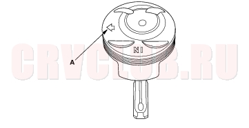
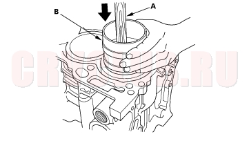
- Position the arrow (A) facing the timing chain side of the engine.
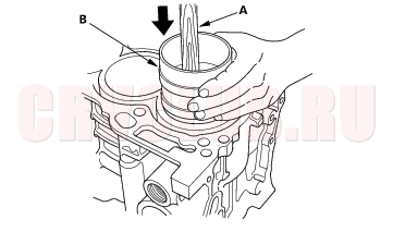
- Position the piston in the cylinder, and tap it in using the wooden handle of a hammer (A).
Maintain downward force on the ring compressor (B) to prevent the rings from expanding before entering the cylinder bore.
- Stop after the ring compressor pops free, and check the connecting rod-to-crank journal alignment before pushing the piston into place.
- Check the connecting rod bearing clearance with plastigage (see page 07-8) .
- Inspect the connecting rod bolts (see page 07-24) .
- Apply engine oil to the bolt threads, then install the rod caps with bearings. Torque the bolts to 20 N·m (2.0 kg·m, 14 lbf·ft) + 90°.
If the crankshaft is not installed
- Remove the connecting rod caps, then install the ring compressor, and check that the bearing is securely in place.
- Position the arrow (A) facing the timing chain side of the engine.
- Position the piston in the cylinder, and tap it in using the wooden handle of a hammer (A).
Maintain downward force on the ring compressor (B) to prevent the rings from expanding before entering the cylinder bore.
- Position all pistons at top dead center.
Connecting Rod Bolt Inspection07-24
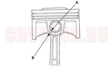
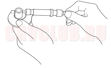
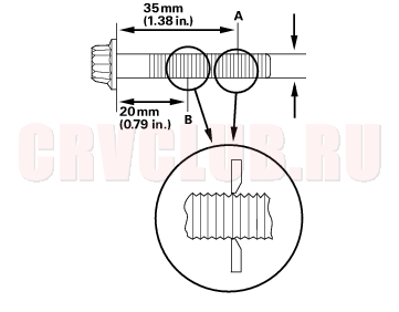
- Measure the diameter of each connecting rod bolt at point A and point B.
- Calculate the difference in diameter between point A and point B.
Point A - Point B = Difference in Diameter
Difference in Diameter:
Specification: 0 - 0.1 mm (0 - 0.004 in.)
Crankshaft Installation07-24
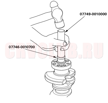
Special Tools Required
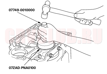
Handle driver 07749-0010000 Driver attachment, 24 x 26 mm 07746-0010700 Oil seal driver attachment 96 07ZAD-PNA0100
- With a manual transmission, install the crankshaft end bushing when replacing the crankshaft.
- Using the special tools, drive in the crankshaft end bushing until the special tools bottom against the crankshaft.
- Check the connecting rod bearing clearance with plastigage (see page 07-8) .
- Check the main bearing clearance with plastigage (see page 07-6) .
- Inspect the connecting rod bolts (see page 07-24) .
07-25
- Install the bearing halves in the cylinder block and connecting rods.
- Apply a coat of engine oil to the main bearings and rod bearings.
- Hold the crankshaft so rod journal No. 2 and rod journal No. 3 are straight up, and lower the crankshaft into the block.
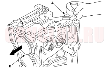
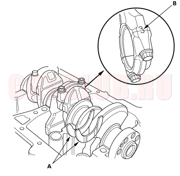
- Install the thrust washers (A) in the No. 4 journal of the cylinder block.
- Apply engine oil to the threads of the connecting rod bolts.
- Seat the rod journals into connecting rod No. 1 and connecting rod No. 4. Line up the mark (B) on the connecting rod and cap, then install the caps and bolts finger-tight.
- Rotate the crankshaft clockwise, and seat the journals into connecting rod No. 2 and connecting rod No. 3. Line up the mark on the connecting rod and cap, then install the caps and bolts finger-tight.
- Tighten the connecting rod bolts to 20 N·m (2.0 kgf·m, 14 lbf·ft).
- Tighten the connecting rod bolts an additional 90°.
- Remove old liquid gasket from the lower block mating surfaces, bolts and bolt holes.
- Clean and dry the lower block mating surfaces.
- Apply liquid gasket, P/N 08C70-K0234M, 08C70-K0334M or 08C70-X0331S, evenly to the cylinder block mating surface of the lower block and to the inner threads of the bolt holes.
- NOTE: Do not install the parts if 5 minutes or more have elapsed since applying liquid gasket. Instead, reapply liquid gasket after removing old residue.
Crankshaft Installation (cont'd)07-26
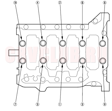
- Put the lower block on the cylinder block.
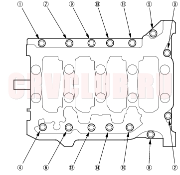
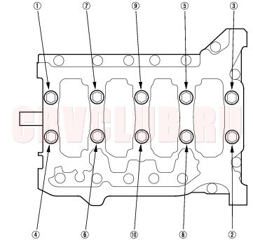
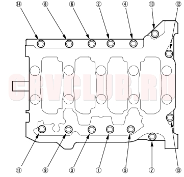
- Tighten the bearing cap bolts in sequence to 29 N·m (3.0 kgf·m, 22 lbf·ft).
- Tighten the bearing cap bolts an additional 56°.
- Tighten the 8 mm bolts in sequence to 22 N·m (2.2 kgf·m, 16 lbf·ft).
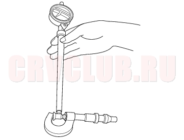
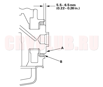
- Use the special tools to drive a new oil seal squarely into the block to the specified installed height.
- Measure the distance between the crankshaft (A) and oil seal (B).
Oil Seal Installed Height: 5.5 - 6.5 mm
(0.22 - 0.26 in.)
07-27
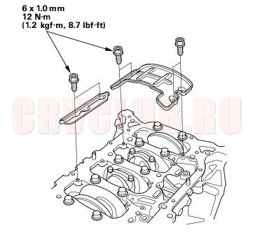
- Install the baffle plates.
- Install the oil pump (see page 08-16) .
- Install the oil pan (see page 07-27) .
- Install the cylinder head (see page 06-40) .
- Install the transmission:
- Manual transmission (see page 13-10) .
- Automatic transmission (see page 14-143) .
- Install the engine assembly (see page 05-10) .
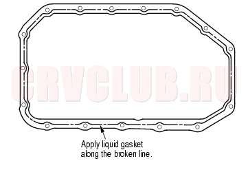
Oil Pan Installation07-27
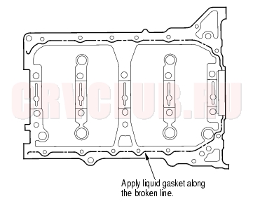
- Remove old liquid gasket from the oil pan mating surfaces, bolts, and bolt holes.
- Clean and dry the oil pan mating surfaces.
- Apply liquid gasket, P/N 08C70-K0334M or 08C70-X0331S, evenly to the cylinder block mating surface of the oil pan and to the inner threads of the bolt holes.
- NOTE: Do not install the parts if 5 minutes or more have elapsed since applying liquid gasket. Instead, reapply liquid gasket after removing old residue.
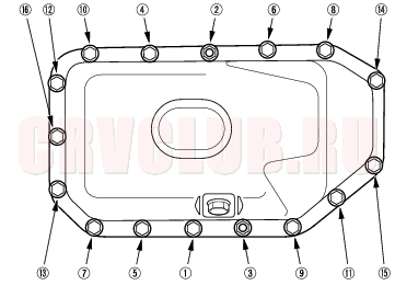
- Install the oil pan.
- Tighten the bolts in two or three steps. In the final step, tighten all bolts, in sequence, to 12 N·m (1.2 kgf·m, 8.7 lbf·ft).
Oil Pan Installation (cont'd)07-28
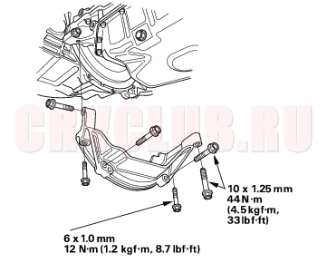
- Install the stiffener (K24A1 engine M/T).
- If the engine is still in the vehicle, install the sub-frame.
- Install the sub-frame. Align the reference lines on the sub-frame with the bolt head center, then tighten the bolts (see step 4 on page 05-11 ).
- Install the ATF filter mounting bolt (see step 21 on page 05-13 ).
- Tighten the front mounting bolt (see step 5 on page 05-11 ).
- Tighten the rear mount mounting bolts (see step 6 on page 05-12 ).
- Connect the suspension lower arm ball joints (see page 18-20 ).
- After assembly, wait at least 30 minutes before filling the engine with oil.
|
Engine Mechanical07-1
Engine Block07-2 |