Cylinder Head06-2
|
Engine Mechanical06-1
Cylinder Head06-2 |
Cylinder Head06-2
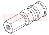
Special Tools
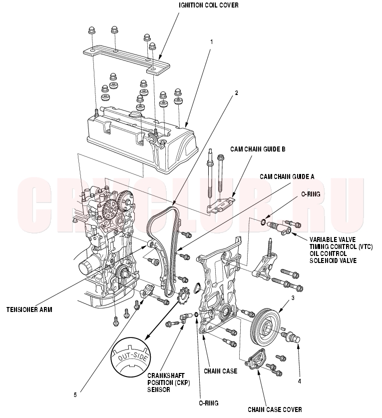
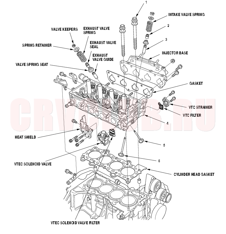
Component Location Index06-3
Removal, page 06-23 Installation, page 06-42 Removal, page 06-12 Installation, page 06-15 Inspection, page 06-22 Replacement, page 06-11 Replacement, page 06-11 Replacement, page 06-19
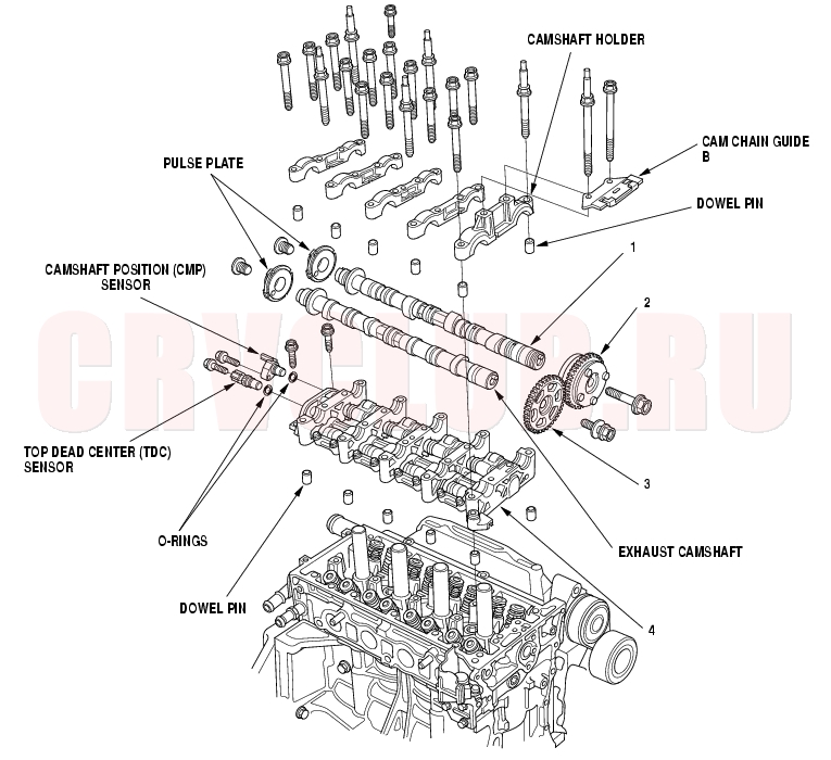
Component Location Index (cont'd)06-4
Inspection, page 06-30 Removal, page 06-25 Installation, page 06-26 Removal, page 06-25 Installation, page 06-26 Overhaul, page 06-28 Inspection, page 06-29
06-5
Inspection, page 06-40 Replacement, page 06-32 Replacement, page 06-34 Removal, page 06-34 Inspection, page 06-26 Installation, page 06-40 Removal, page 06-32 Installation, page 06-38 Removal, page 06-32 Installation, page 06-38
Engine Compression Inspection06-6
- Warm up the engine to normal operating temperature (cooling fan comes on).
- Turn the ignition switch OFF.
- Remove the intake manifold cover (see step 1 on page 06-23 ).
- Disconnect all four injector connectors.
- Start the engine, and let it run until it stalls.
- Remove the four ignition coils (see page 04-21) .
- Remove the four spark plugs.
- Attach the compression gauge to the spark plug hole.
- Connect a tachometer.
- Open the throttle fully, then crank the engine with the starter motor and measure the compression.
Compression Pressure:
Above 930 kpa (9.5 kgf/cm² 135 psi)-250 rpm (min-1)
Maximum variation:
Within 200 kPa (2.0 kgf/cm², 28 psi)
- If the compression is not within specifications, check the following items, then remeasure the compression.
- Damaged or worn valves and seats
- Damaged cylinder head gasket
- Damaged or worn piston rings
- Damaged or worn piston and cylinder bore
VTEC Rocker Arm Test06-7
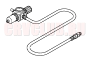
Special Tools Required
Valve inspection set 07LAJ-PR30101 VTEC air adapter 07ZAJ-PNA0101 VTEC air stopper 07ZAJ-PNA0200 Air joint adapter 07ZAJ-PNA0300 Air socket adapter 07ZAJ-PNA0400
- Remove the cylinder head cover (see page 06-23) .
- Set the No. 1 piston at Top Dead Center (TDC), (see step 1 on page 06-12 ).
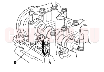
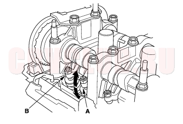
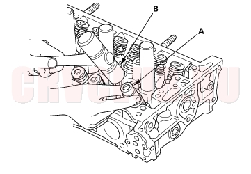
- Verify that the intake primary rocker arm (A) moves independently of the intake secondary rocker arm (B).
- If the intake primary rocker arm does not move, remove the primary and secondary rocker arms as an assembly and check that the pistons in the secondary and primary rocker arms move smoothly. If any rocker arm needs replacing, replace the primary and secondary rocker arms as an assembly, and test.
- If the intake primary rocker arm moves freely, go to step 4.
- Repeat step 3 on the remaining intake primary rocker arms with each piston at TDC. When all the primary rocker arms pass the test, go to step 5.
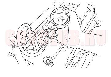
- Check that the air pressure on the shop air compressor gauge indicates over 400 kPa (4 kgf/cm², 57 psi).
- Inspect the valve clearance (see page 06-9) .
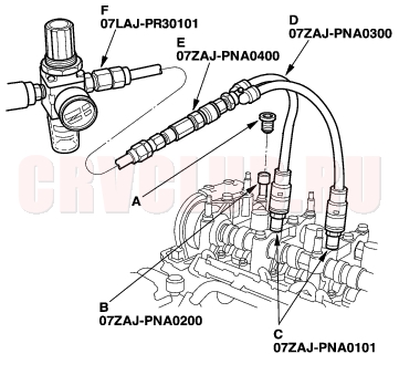
- Remove the sealing bolt (A) from the relief hole, and install the VTEC air stopper (B).
- Remove the No. 2 and No. 3 camshaft holder bolts, and install the VTEC air adapters (C) finger-tight.
- Connect the air joint adapter (D), air socket adapter (E), and valve inspection set (F).
VTEC Rocker Arm Test (cont'd)t06-8
Specified air pressure:
290 kPa (3.0m kgf/cm², 42 psi)
NOTE: If the synchronizing piston does not move after applying air pressure; move the primary or secondary rocker arm up and down manually by rotating the crankshaft clockwise.
- With the specified air pressure applied, move the intake primary rocker arm (A) for the No. 1 cylinder. The primary rocker arm and secondary rocker arm (B) should move together.
- If the intake secondary rocker arm does not move, remove the primary and secondary rocker arms as an assembly and check that the pistons in the primary and secondary rocker arms move smoothly. If any rocker arm needs replacing, replace the primary and secondary rocker arms as an assembly, and test.
- Remove the special tools.
- Tighten the camshaft holder mounting bolts to 22 N·m (2.2 kgf·m, 16 lbf·ft).
- Tighten the sealing bolt to 20 N·m (2.0 kgf·m, 14 lbf·ft).
- Install the cylinder head cover (see page 06-42) .
VTC Actuator Inspection06-8
- Remove the cylinder head cover (see page 06-23) .
- Remove the auto-tensioner (see page 06-19) .
- Loosen the rocker arm adjusting screws (see step 2 on page 06-27 ).
- Remove the camshaft holder (see step 3 on page 06-27 ).
- Remove the intake camshaft.
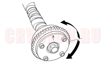
- Check that the Variable Valve Timing Control (VTC) actuator is locked by turning the VTC actuator clockwise and counterclockwise. If the VTC actuator is not locked, replace the VTC actuator.
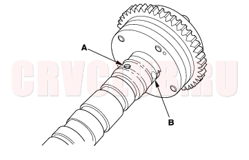
- Seal the advance holes (A) and retard holes (B) in the No. 1 camshaft journal with the tape.
- Punch a hole in the tape over one of the advance holes.
06-9
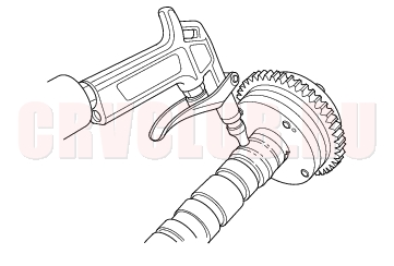
- Apply air to the advance hole to release the lock.
- Check that the VTC actuator moves smoothly. If the VTC actuator does not move smoothly, replace the VTC actuator.
Valve Clearance Adjustment06-9
NOTE: Adjust the valves only when the cylinder head temperature is less than 38°C (100°F).
- Remove the cylinder head cover (see page 06-23) .
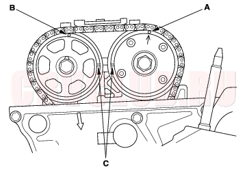
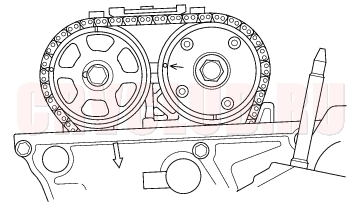
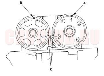
- Set the No. 1 piston at Top Dead Center (TDC). The punch mark (A) marked with an arrow on the Variable Valve Timing Control (VTC) actuator and the punch mark (B) on the exhaust camshaft sprocket should be at the top. Align the TDC marks (C) on the VTC actuator and exhaust camshaft sprocket.
Valve Clearance Adjustment (cont'd)06-10
Intake: 0.21 - 0.25 mm (0.008 - 0.010 in.)
Exhaust: 0.28 - 0.32 mm (0.011 - 0.013 in.)
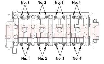
Adjusting screw locations:
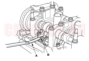
- Insert the feeler gauge (A) between the adjusting screw (B) and the end of the valve stem and slide it back and forth; you should feel a slight amount of drag.
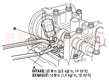
- If you feel too much or too little drag, loosen the locknut (A), and turn the adjusting screw (B) until the drag on the feeler gauge is correct.
- Tighten the locknut and recheck the clearance. Repeat the adjustment if necessary.
- Rotate the crankshaft 180° clockwise (camshaft pulley turns 90°).
- Check and, if necessary, adjust the valve clearance on No. 3 cylinder.
06-11
- Rotate the crankshaft 180° clockwise camshaft pulley turns 90°).
- Check and, if necessary, adjust the valve clearance on No. 4 cylinder.
- Rotate the crankshaft 180°) clockwise (camshaft pulley turns 90°).
- Check and, if necessary, adjust the valve clearance on No. 2 cylinder.
- Install the cylinder head cover (see page 06-42) .
Crankshaft Pulley Removal and Installation06-11
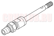
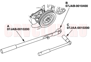
Special Tools Required
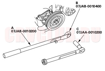
Handle 07JAB-0010200 Pulley holder attachment, HEX 50 mm 07JAB-0010400 Socket wrench, 19 mm 07JAA-0010200 Removal
- Remove front tires/wheels.
- Remove the splash shield (see step 3 on page 06-12 ).
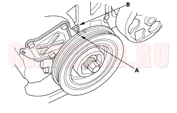
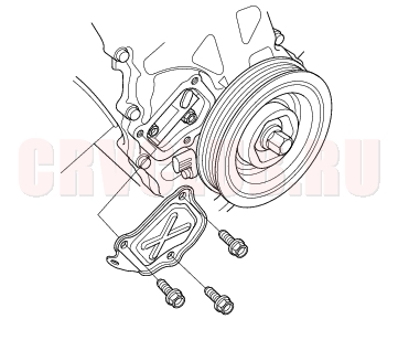
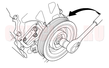
- Hold the pulley with handle (A) and holder attachment (B).
- Remove the bolt with a 19 mm socket (C) and breaker bar.
Crankshaft Pulley Removal and Installation (cont'd)06-12
Installation
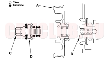
- Clean the crankshaft pulley (A), crankshaft (B), bolt (C), and washer (D). Lubricate as shown below.
- Install the crankshaft pulley, and hold the pulley with handle (A) and holder attachment (B).
- Tighten the bolt to 245 N·m (25.0 kgf·m, 181 lbf·ft) with a torque wrench and 19 mm socket (C). Do not use an impact wrench.
- Install the splash shield (see step 24 on page 06-19 ).
- Install front tires/wheels.
Cam Chain Removal06-12
NOTE: Keep the cam chain away from magnetic fields.
- Turn the crankshaft pulley so its Top Dead Center (TDC) mark (A) lines up with the pointer (B).
- Remove the front tires/wheels.
- Remove the splash shield.
- Remove the drive belt (see page 04-29) .
- Remove the cylinder head cover (see page 06-23) .
- Remove the crankshaft pulley (see page 06-11) .
06-13
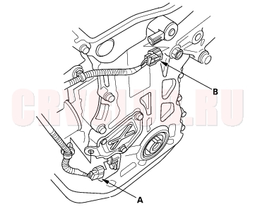
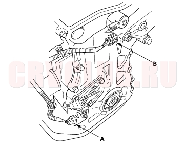
- Disconnect the Crankshaft Position (CKP) sensor connector (A) and Variable Valve Timing Control (VTC) oil control solenoid valve connector (B).
- Remove the VTC oil control solenoid valve (see step 1 on page 11-137 ).
- Support the engine with a jack and wood block under the oil pan.
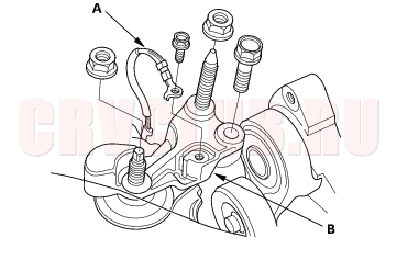
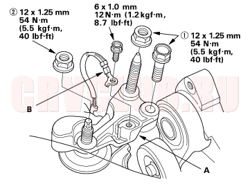
- Remove the ground cable (A), and remove the upper bracket (B).
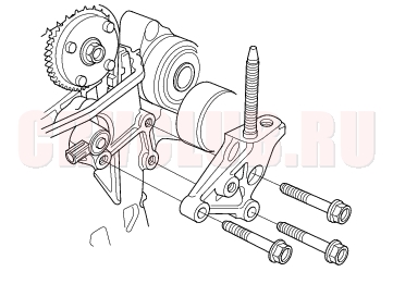
- Remove the side engine mount bracket.
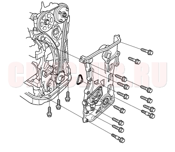
- Remove the chain case.
Cam Chain Removal (cont'd)06-14
- Loosely install the crankshaft pulley.
- Turn the crankshaft counterclockwise to compress the auto-tensioner.
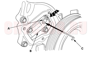
- Align the holes on the lock (A) and the auto-tensioner (B), then insert a 1.5 mm (0.06 in.) diameter pin (C) into the holes. Turn the crankshaft clockwise to secure the pin.
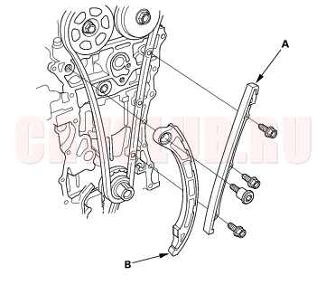
- Remove the auto-tensioner.
- Remove the cam chain guide B.
06-15
Cam Chain Installation06-15
NOTE: Keep the cam chain away from magnetic fields.
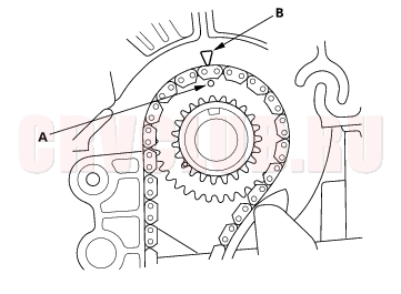
- Set the crankshaft to Top Dead Center (TDC). Align the TDC mark (A) on the crankshaft sprocket with the pointer (B) on the cylinder block.
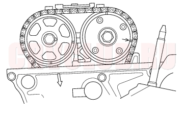
- Set the camshafts to TDC. The punch mark (A) marked with an arrow on the Variable Valve Timing Control (VTC) actuator and the punch mark (B) on the exhaust camshaft sprocket should be at the top. Align the TDC marks (C) on the VTC actuator and exhaust camshaft sprocket.
Cam Chain Installation (cont'd)06-16
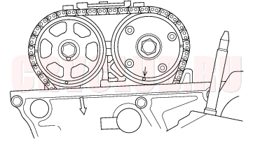
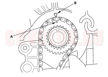
- Install the cam chain on the crankshaft sprocket with the colored piece (A) aligned with the punch mark (B) on the crankshaft sprocket.
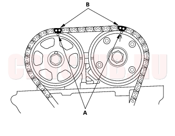
- Install the cam chain on the VTC actuator and exhaust camshaft sprocket with the punch marks (A) aligned with the two colored pieces (B).
- Install the cam chain guide A (A) and tensioner arm (B).
- Install the auto-tensioner.
06-17
- Install the cam chain guide B.
- Remove the pin from the auto-tensioner.
- Check the chain case oil seal for damage. If the oil seal is damaged, replace the chain case oil seal (see page 06-21) .
- Remove old liquid gasket from the chain case mating surfaces, bolts, and bolt holes.
- Clean and dry the chain case mating surfaces.
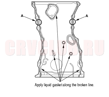
- Apply liquid gasket, P/N 08C70-K0234M, 08C70-K0334M or 08C70-X0331S, evenly to the cylinder block mating surface of the chain case and to the inner threads of the holes.
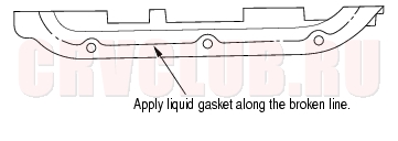
- Apply liquid gasket to the cylinder block upper surface contact areas (A) on the chain case.
- Apply liquid gasket, P/N 08C70-K0334M or 08C70-X0331S, evenly to the oil pan mating surface of the chain case and to the inner threads of the holes.
- NOTE: Do not install the parts if 5 minutes or more have elapsed since applying liquid gasket. Instead, reapply liquid gasket after removing old residue.
Cam Chain Installation (cont'd)06-18
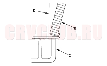
- Install the new O-ring (A) on the chain case. Set the edge of the chain case (B) to the edge of the oil pan (C), then install the chain case on the cylinder block (D).
- NOTE: When installing the chain case, do not slide the bottom surface on the oil pan mounting surface.
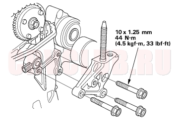
- Install the side engine mount bracket.
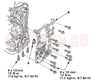
- Install the upper bracket (A), then tighten the bolt/nuts in the numbered sequence shown.
- Install the ground cable (B).
06-19
- Install the VTC oil control solenoid valve (see step 1 on page 11-137 ).
- Connect the Crankshaft Position (CKP) sensor connector (A) and VTC oil control solenoid valve connector (B).
- Install the crankshaft pulley (see page 06-11) .
- Install the cylinder head cover (see page 06-42) .
- Install the drive belt.
- Install the splash shield.
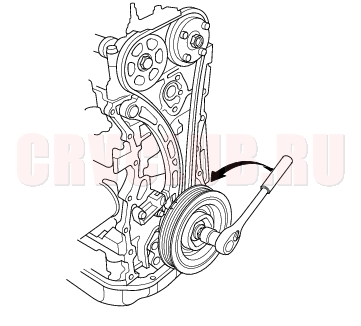
Auto-Tensioner Removal/Installation06-19
Removal:
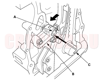
Auto-Tensioner Removal/Installation (cont'd)06-20
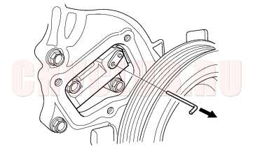
- Align the holes on the lock (A) and the auto-tensioner (B), then insert a 1.5 mm (0.06 in.) diameter pin (C) into the holes. Turn the crankshaft clockwise to secure the pin.
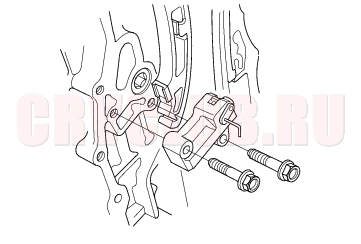
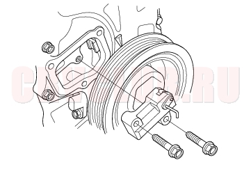
- Remove the auto-tensioner.
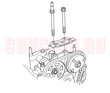
Installation:
06-21
- Remove old liquid gasket from the chain case cover mating surfaces, bolts and bolt holes.
- Clean and dry the chain case cover mating surfaces.
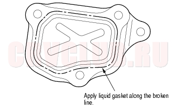
- Apply liquid gasket, P/N 08C70-K0234M, 08C70-K0334M or 08C70-X0331S, evenly to the chain case mating surface of the chain case cover and to the inner threads of the holes.
- NOTE: Do not install the parts if 5 minutes or more have elapsed since applying liquid gasket. Instead, reapply liquid gasket after removing old residue.
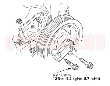
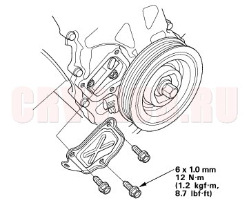
- Install the chain case cover.
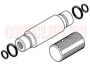
Chain Case Oil Seal Installation06-21
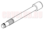
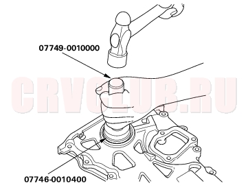
Special Tools Required
Handle driver 07749-0010000 Driver attachment, 52 x 55 mm 07746-0010400
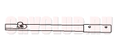
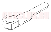
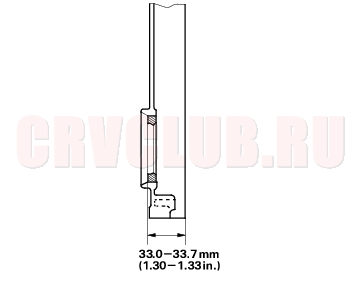
- Use the special tools to drive a new oil seal squarely into the chain case to the specified installed height.
- Measure the distance between the chain case surface and oil seal.
Oil Seal Installed Height:
33.0 - 33.7 mm (1.30 - 1.33 in.)
Cam Chain Inspection06-22
- Remove the front tires/wheels.
- Remove the splash shield (see step 3 on page 06-12 ).
- Remove the drive belt (see page 04-30) .
- Remove the cylinder head cover (see page 06-23) .
- Remove the crankshaft pulley (see step 7 on page 06-13 ).
- Disconnect the Crankshaft Position (CKP) sensor connector and Variable Valve Timing Control (VTC) oil control solenoid valve connector (see step 7 on page 06-13 ).
- Remove the VTC oil control valve (see step 1 on page 11-137 ).
- Support the engine with a jack and wood block under the oil pan.
- Remove the ground cable, and remove the upper bracket (see step 10 on page 06-13 ).
- Remove the side engine mount bracket (see step 11 on page 06-13 ).
- Remove the chain case (see step 12 on page 06-13 ).
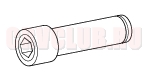
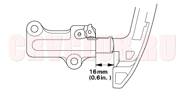
- Measure the tensioner rod length. If the length is over the tolerance, replace the cam chain and oil pump chain.
Tensioner Rod Length
Service Limit: 16 mm (0.6 in.)
- Check the chain case oil seal for damage. If the oil seal is damaged, replace the chain case oil seal (see page 06-21) .
- Remove old liquid gasket from the chain case mating surfaces, bolts and bolt holes.
- Clean and dry the chain case mating surfaces.
- Apply liquid gasket, P/N 08C70-K0234M, 08C70-K0334M or 08C70-X0331S, evenly to the cylinder block mating surface of the chain case and to the inner threads of the holes (see step 12 on page 06-17 ).
- Apply liquid gasket to the cylinder block upper surface contact areas on the chain case (see step 13 on page 06-17 ).
- Apply liquid gasket, P/N 08C70-K0334M or 08C70-X0331S, evenly to the oil pan mating surface of the chain case and to the inner threads of the holes (see step 14 on page 06-17 ).
- NOTE: Do not install the parts if 5 minutes or more have elapsed since applying liquid gasket. Instead, reapply liquid gasket after removing old residue.
- Install the new O-ring on the chain case. Set the edge of the chain case to the edge of the oil pan, then install the chain case on the cylinder block (see step 15 on page 06-18 ).
- NOTE: When installing the chain case, do not slide the bottom surface on the oil pan mounting surface.
- Install the side engine mount bracket (see step 16 on page 06-18 ).
- Install the upper bracket and the ground cable (see step 17 on page 06-18 ).
- Install the VTC oil control solenoid valve (see page 11-137) .
- Connect the CKP sensor connector and VTC oil control solenoid valve connector (see step 20 on page 06-19 ).
- Install the crankshaft pulley (see page 06-12) .
- Install the cylinder head cover (see page 06-42) .
- Install the drive belt.
- Install the splash shield (see step 24 on page 06-19 ).
- Install the front tires/wheels.
Cylinder Head Cover Removal06-23
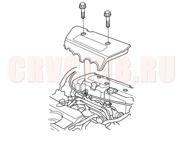
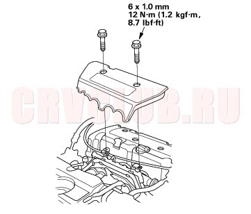
- Remove the intake manifold cover.
- Remove the four ignition coils (see page 04-21) .
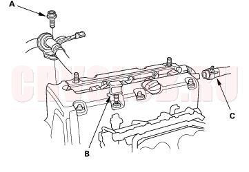
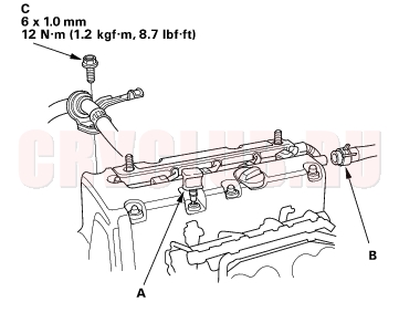
- Remove the bolt (A) securing the power steering hose bracket.
- Remove the dipstick (B) and breather hose (C).
- Remove the cylinder head cover.
Cylinder Head Removal06-24
Use fender covers to avoid damaging painted surfaces. To avoid damage, unplug the wiring connectors carefully while holding the connector portion. To avoid damaging the cylinder head, wait until the engine coolant temperature drops below 38°C (100°F) before loosening the cylinder head bolts. Mark all wiring and hoses to avoid misconnection. Also, be sure that they do not contact other wiring or hoses, or interfere with other parts.
- Drain the engine coolant (see page 10-6) .
- Relieve fuel pressure (see page 11-154) .
- Disconnect the fuel feed hose (see page 11-156) .
- Remove the drive belt (see page 04-30) .
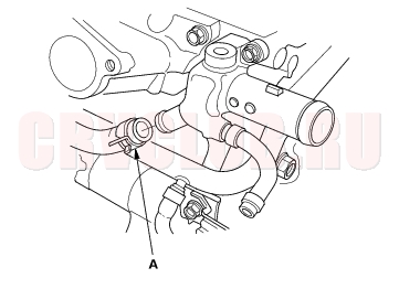
- Remove the intake manifold (see page 09-3) .
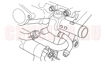
- Remove the water bypass hose (A).
- Remove the exhaust manifold (see page 09-8) .
- Remove the cam chain (see page 06-12) .
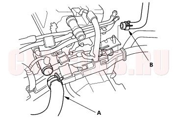
- Remove the engine wire harness connectors and wire harness clamps from the cylinder head.
- Four injector connectors
- Engine Coolant Temperature (ECT) sensor connector
- Top Dead Center (TDC) sensor connector
- Camshaft Position (CMP) sensor connector
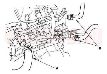
- Remove the upper radiator hose (A) and heater hose (B).
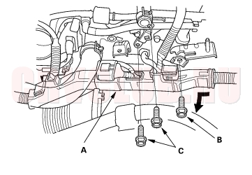
- Remove the harness holder (A) from the bracket, then remove the connecting pipe mounting bolt (B) and brake booster vacuum line mounting bolts (C).
06-25
- Remove the rocker arm assembly (see page 06-27) .
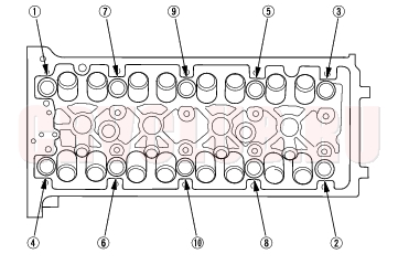
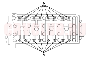
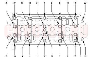
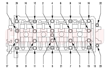
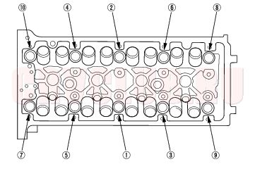
- Remove the cylinder head bolts. To prevent warpage, unscrew the bolts in sequence 1/3 turn at a time; repeat the sequence until all bolts are loosened.
CYLINDER HEAD BOLTS LOOSENING SEQUENCE:
VTC Actuator, Exhaust Camshaft Sprocket Replacement06-25
Removal:
- Remove the cam chain (see page 06-12) .
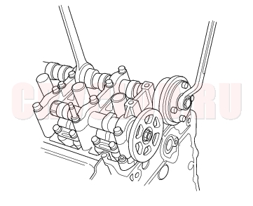
- Hold the camshaft with an open-end wrench, then loosen the Variable Valve Timing Control (VTC) actuator mounting bolt and exhaust camshaft sprocket mounting bolt.
- Remove the VTC actuator and exhaust camshaft sprocket.
VTC Actuator, Exhaust Camshaft Sprocket Replacement (cont'd)06-26
Installation:
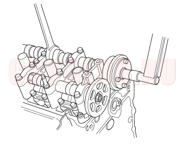
- Install the VTC actuator and exhaust camshaft sprocket.
- Apply engine oil to the threads of the VTC actuator mounting bolt and exhaust camshaft mounting bolt, then install them.
- Hold the camshaft with an open-end wrench, then tighten the bolts.
Specified torque:
VTC actuator mounting bolt:
113 N·m (11.5 kgf·m, 83 lbf·ft)
Exhaust camshaft sprocket mounting bolt:
72 N·m (7.3 kgf·m, 53 lbf·ft)
- Install the cam chain (see page 06-15) .
Cylinder Head Inspection for Warpage06-26
- Remove the cylinder head (see page 06-24) .
- Inspect the camshaft (see page 06-30) .
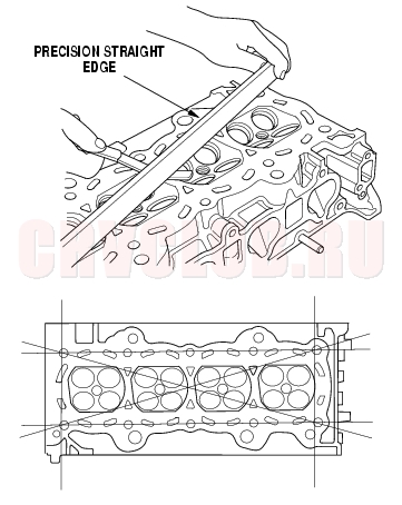
- Check the cylinder head for warpage. Measure along the edges, and three ways across the center.
- If warpage is less than 0.05 mm (0.002 in.) cylinder head resurfacing is not required.
- If warpage is between 0.05 mm (0.002 in.) and 0.2 mm (0.008 in.), resurface the cylinder head.
- Maximum resurface limit is 0.2 mm (0.008 in.) based on a height of 104 mm (4.09 in.).
Cylinder Head Height:
Standard (New): 103.95 - 104.05 mm
(4.093 -4.096 in.)
Rocker Arm Assembly Removal06-27
- Remove the cam chain (see page 06-12) .
- Loosen the rocker arm adjusting screws (A).
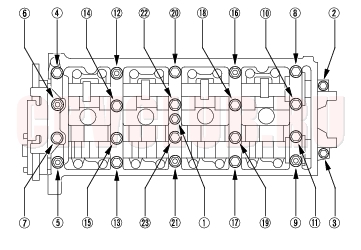
- Remove the camshaft holder bolts. To prevent damaging the camshafts, unscrew the bolts two turns at a time, in a crisscross pattern.
CAMSHAFT HOLDER BOLTS LOOSENING SEQUENCE:
- Remove the cam chain guide B, camshaft holders, and camshafts.
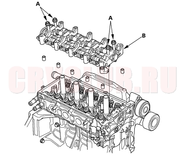
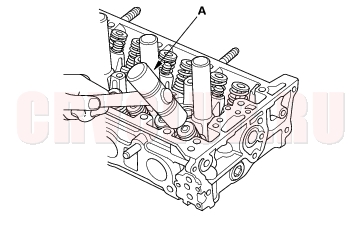
- Insert the bolts (A) into the rocker shaft holder, then remove the rocker arm assembly (B).
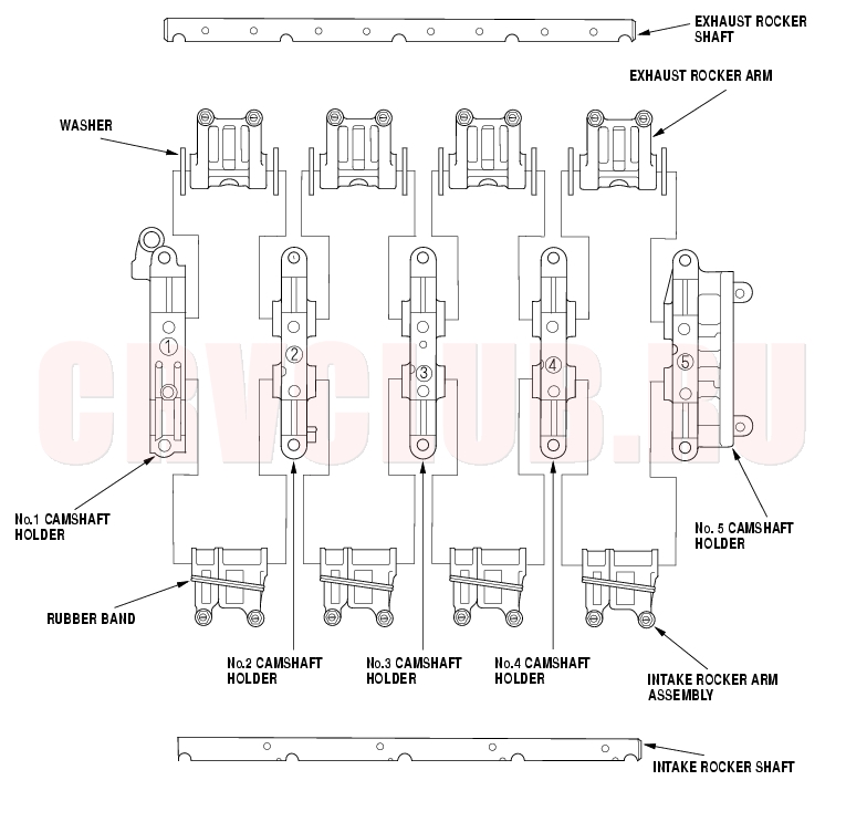
Rocker Arms and Shafts Disassembly/Reassembly06-28
Identify parts as they are removed to ensure reinstallation in original location. Inspect the rocker shafts and rocker arms (see page 06-29) . The rocker arms must be installed in the same positions if reused. When removing or installing the rocker arm assembly, do not remove the camshaft holder bolts. The bolts will keep the holders, springs and rocker arms on the shaft. Prior to reassembling, clean all the parts in solvent, dry them, and apply lubricant to any contact points. Bundle the rocker arms with rubber bands to keep them together as a set.
Rocker Arms and Shafts Inspection06-29
- Remove the rocker arm assembly (see page 06-27) .
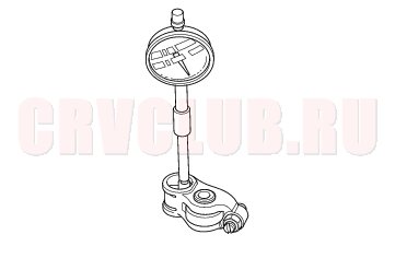
- Measure the diameter of the shaft at the first rocker location.
- Zero the gauge (A) to the shaft diameter.
- Measure the inside diameter of the rocker arm, and check it for an out-of-round condition.
Rocker Arm-to-Shaft Clearance:
Standard (New):
Intake: 0.025 - 0.052 mm
(0.0010 - 0.0020 in.)
Exhaust: 0.018 - 0.056 mm
(0.0007 0.0022 in.)
Service Limit: 0.08 mm (0.003 in.)
- Repeat for all rocker arms and both shafts. If the clearance is over the limit, replace the rocker shaft and all overtolerance rocker arms. If any VTEC rocker arm needs replacement, replace rocker arms (primary and secondary) as a set.
Rocker Arms and Shafts Inspection (cont'd)06-30
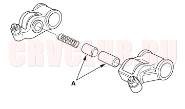
- Inspect the rocker arm pistons (A). Push each piston manually.
If it does not move smoothly, replace the rocker arm set.
- NOTE: Apply oil to the pistons when reassembling.
Camshaft Inspection06-30
NOTE: Do not rotate the camshaft during inspection.
- Remove the rocker arm assembly (see page 06-27) .
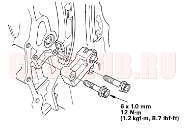
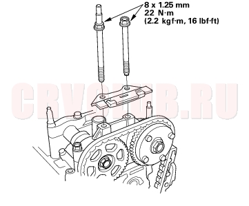
- Put the rocker shaft holders, camshaft and camshaft holders on the cylinder head, then tighten the bolts to the specified torque.
Specified torque:
8 mm bolts:
22 N·m (2.2 kgf·m, 16 lbf·ft)
6 mm bolts:
12 N·m (1.2 kgf·m, 8.7 lbf·ft)
6 mm bolts: 21, 22, 23
06-31
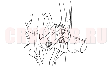
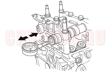
- Seat the camshaft by pushing it away from the camshaft pulley end of the cylinder head.
- Zero the dial indicator against the end of the camshaft, then push the camshaft back and forth and read the end play. If the end play is beyond the service limit, replace the cylinder head and recheck. If it is still beyond the service limit, replace the camshaft.
Camshaft End Play:
Standard (New): 0.05 - 0.20 mm
(0.002 - 0.008 in.)
Service Limit: 0.4 mm (0.02 in.)
- Unscrew the camshaft holder bolts two turns at a time, in a crisscross pattern. Then remove the camshaft holders from the cylinder head.
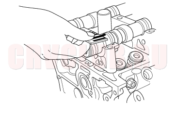
- Lift the camshafts out of the cylinder head, wipe them clean, then inspect the lift ramps. Replace the camshaft if any lobes are pitted, scored, or excessively worn.
- Clean the camshaft journal surfaces in the cylinder head, then set the camshafts back in place. Place a plastigage strip across each journal.
- Install the camshaft holders, then tighten the bolts to the specified torque as shown in step 2.
- Remove the camshaft holders. Measure the widest portion of plastigage on each journal.
- If the camshaft-to-holder clearance is within limits, go to step 11.
- If the camshaft-to-holder clearance is beyond the service limit and the camshaft has been replaced, replace the cylinder head.
- If the camshaft-to-holder clearance is beyond the service limit and the camshaft has not been replaced, go to step 10.
Camshaft-to-Holder Oil Clearance:
Standard (New):
No. 1 Journal: 0.030 - 0.069 mm
(0.001 - 0.003 in.)
No. 2, 3, 4, 5 Journals: 0.060 - 0.099 mm
(0.002 - 0.004 in.)
Service Limit: 0.15 mm (0.006 in.)
Camshaft Inspection (cont'd)06-32
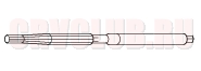
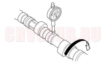
- Check the total runout with the camshaft supported on V-blocks.
- If the total runout of the camshaft is within the service limit, replace the cylinder head.
- If the total runout is beyond the service limit, replace the camshaft and recheck the camshaft-to-holder oil clearance. If the oil clearance is still beyond the service limit, replace the cylinder head.
Camshaft Total Runout:
Standard (New): 0.03 mm (0.001 in.) max.
Service Limit: 0.04 mm (0.002 in.)
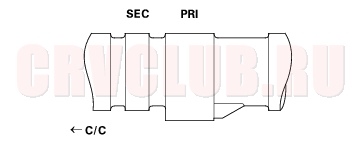
- Measure cam lobe height.
Cam Lobe Height Standard (New):
PRI 33.925 mm (1.3356 in.) 34.092 mm (1.3422 in.) SEC 29.638 mm (1.1668 in.)
- PRI: Primary SEC: Secondary
- C/C: Cam Chain
Valves, Springs and Valve Seals Removal06-32
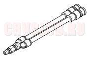
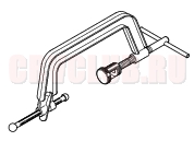
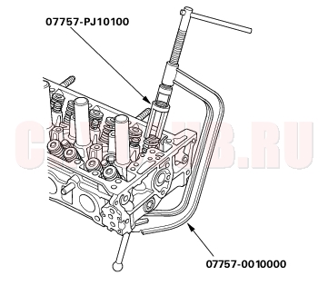
Special Tools Required
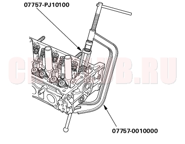
Valve spring compressor attachment 07757-PJ10100 Valve spring compressor 07757-0010000 Identify the valves and valve springs as they are removed so that each item can be reinstalled in its original position.
- Remove the cylinder head (see page 06-24) .
- Using an appropriate-sized socket (A) and plastic mallet (B), lightly tap the valve retainer to loosen the valve keepers.
- Install the spring compressor. Compress the spring, and remove the valve keepers.
Valve Inspection06-33
- Remove the valves (see page 06-32) .
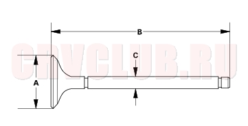
- Measure the valve in these areas.
Intake Valve Dimensions:
A Standard (New): 34.85 - 35.15 mm
(1.372 - 1.384 in.)
B Standard (New): 108.7 - 109.5 mm
(4.280 - 4.311 in.)
C Standard (New): 5.475 - 5.485 mm
(0.2156 - 0.2159 in.)
C Service Limit: 5.445 mm (0.214 in.)
Exhaust Valve Dimensions:
A Standard (New): 29.85 - 30.15 mm
(1.175 - 1.187 in.)
B Standard (New): 108.3 - 109.1 mm
(4.264 - 4.295 in.)
C Standard (New): 5.450 - 5.460 mm
(0.2146 - 0.2150 in.)
C Service Limit: 5.42 mm (0.213 in.)
Valve Stem-to-Guide Clearance Inspection06-33
- Remove the valves (see page 06-32) .
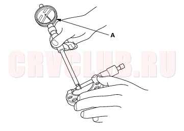
- Slide the valve out of its guide about 10 mm, then measure the guide-to-stem clearance with a dial indicator while rocking the stem in the direction of normal thrust (wobble method).
- If the measurement exceeds the service limit, recheck it using a new valve.
- If the measurement is now within the service limit, reassemble using a new valve.
- If the measurement with a new valve still exceeds the service limit, go to step 3.
Intake Valve Stem-to-Guide Clearance:
Standard (New): 0.06 - 0.11 mm
(0.002 - 0.004 in.)
Service Limit: 0.16 mm (0.006 in.)
Exhaust Valve Stem-to-Guide Clearance:
Standard (New): 0.11 - 0.16 mm
(0.004 - 0.006 in.)
Service Limit: 0.22 mm (0.009 in.)
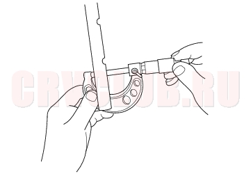
- Subtract the O.D. of the valve stem, measured with a micrometer, from the I.D. of the valve guide, measured with an inside micrometer or ball gauge.
Take the measurements in three places along the valve stem and three places inside the valve guide.
The difference between the largest guide measurement and the smallest stem measurement should not exceed the service limit.
Intake Valve Stem-to-Guide Clearance:
Standard (New): 0.030 - 0.055 mm
(0.0012 - 0.0022 in.)
Service Limit: 0.08 mm (0.003 in.)
Exhaust Valve Stem-to-Guide Clearance:
Standard (New): 0.055 - 0.080 mm
(0.0022 - 0.0031 in.)
Service Limit: 0.11 mm (0.004 in.)
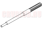
Valve Guide Replacement06-34
Special Tools Required
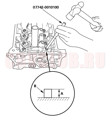
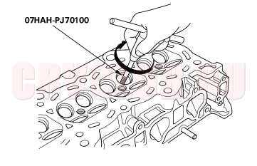
Valve guide driver, 5.5 mm 07742-0010100 Valve guide reamer, 5.525 mm 07HAH-PJ70100
- Inspect valve stem-to-guide clearance (see page 06-33) .
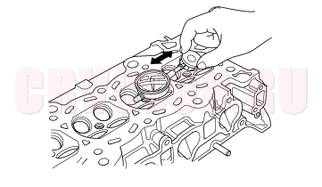
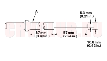
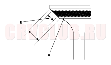
- As illustrated below, use a commercially available air-impact valve guide driver (A) modified to fit the diameter of the valve guides. In most cases, the same procedure can be done using the special tool and a conventional hammer.
- Select the proper replacement guides, and chill them in the freezer section of a refrigerator for about an hour.
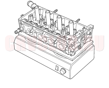
- Use a hot plate or oven to evenly heat the cylinder head to 150°C (300°F). Monitor the temperature with a cooking thermometer. Do not get the head hotter than 150°C (300°F); excessive heat may loosen the valve seats.
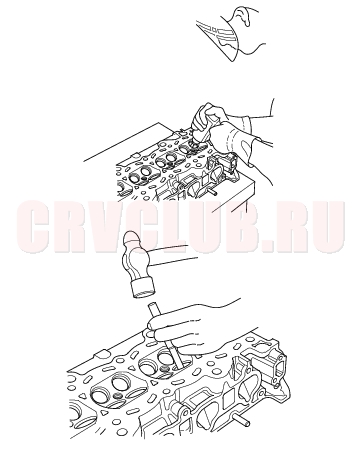
- Working from the camshaft side, use the driver and an air hammer to drive the guide about 2 mm (0.1 in.) towards the combustion chamber. This will knock off some of the carbon and make removal easier. Hold the air hammer directly in line with the valve guide to prevent damaging the driver.
- Turn the head over, and drive the guide out toward the camshaft side of the head.
- If a valve guide won't move, drill it out with a 8 mm (5/16 inch) bit, then try again. Drill guides only in extreme cases; you could damage the cylinder head if the guide breaks.
- Remove the new guide(s) from the freezer, one at a time, as you need them.
06-35
- Apply a thin coat of clean engine oil to the outside of the new valve guide. Install the guide from the camshaft side of the head; use the special tool to drive the guide in to the specified installed height (A) of the guide (B). If you have all 16 guides to do, you may have to reheat the head.
Valve Guide Installed Height:
Intake: 15.2 - 16.2 mm (0.598 - 0.638 in.)
Exhaust: 15.5 - 16.5 mm (0.610 - 0.650 in.)
- Coat both reamer and valve guide with cutting oil.
- Rotate the reamer clockwise the full length of the valve guide bore.
- Continue to rotate the reamer clockwise while removing it from the bore.
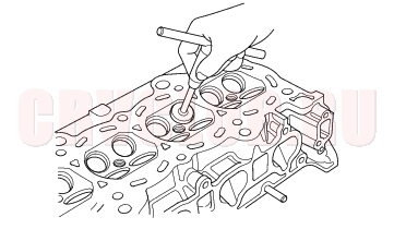
- Thoroughly wash the guide in detergent and water to remove any cutting residue.
- Check the clearances with a valve (see page 06-33) . Verify that a valve slides in the intake and exhaust valve guides without exerting pressure.
Valve Seat Reconditioning06-36
- Inspect valve stem-to-guide clearance (see page 06-33) . If the valve guides are worn, replace them (see page 06-34) before cutting the valve seats.
- Renew the valve seats in the cylinder head using a valve seat cutter.
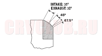
- Carefully cut a 45° seat, removing only enough material to ensure a smooth and concentric seat.
- Bevel the upper and lower edges at the angles shown in the illustration.
Check the width of the seat and adjust accordingly.
- Make one more very light pass with the 45° cutter to remove any possible burrs caused by the other cutters.
Valve Seat Width:
Standard (New): 1.25 - 1.55 mm (0.049 - 0.061 in.)
Service Limit: 2.00 mm (0.079 in.)
- After resurfacing the seat, inspect for even valve seating: Apply Prussian Blue compound (A) to the valve face. Insert the valve in its original location in the head, then lift it and snap it closed against the seat several times.
- The actual valve seating surface (B), as shown by the blue compound, should be centered on the seat.
- If it is too high (closer to the valve stem), you must make a second cut with the 67.5° cutter to move it down, then one more cut with the 45° cutter to restore seat width.
- If it is too low (close to the valve edge), you must make a second cut with the 35° cutter (intake side) or the 30° cutter (exhaust side) to move it up, then make one more cut with the 45° cutter to restore seat width.
- NOTE: The final cut should always be made with the 45° cutter.
06-37
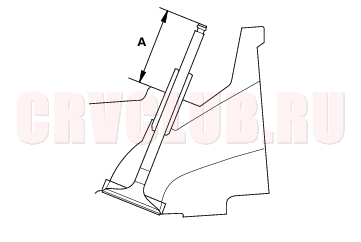
Intake Valve Stem Installed Height:
Standard (New): 40.8 - 41.0 mm
(1.606 - 1.614 in.)
Exhaust Valve Stem Installed Height:
Standard (New): 54.6 - 54.8 mm
(2.150 - 2.157 in.)
- If valve stem installed height is over the standard, replace the valve and recheck. If it is still over the standard, replace the cylinder head; the valve seat in the head is too deep.
Valves, Springs and Valve Seals Installation06-38
Special Tools Required
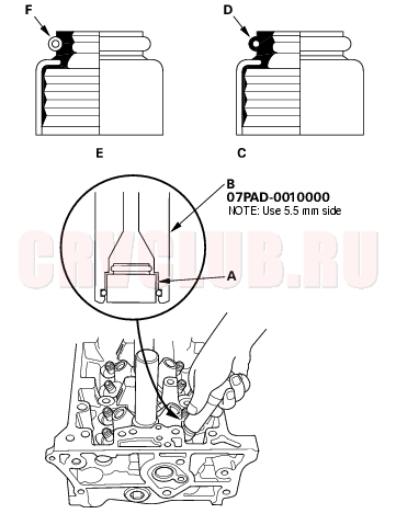
Stem seal driver 07PAD-0010000 Valve spring compressor attachment 07757-PJ10100 Valve spring compressor 07757-0010000
- Coat the valve stems with engine oil. Install the valves in the valve guides.
- Check that the valves move up and down smoothly.
- Install the spring seats on the cylinder head.
- Install the new valve seals (A) using the valve guide seal installer (B).
- NOTE: The exhaust valve seal (C) has a black spring (D), and the intake valve seal (E) has a white spring (F). They are not interchangeable.
- Install the valve spring. Place the end of the valve spring with closely wound coils toward the cylinder head.
- Install the valve retainer.
- Install the valve spring compressor. Compress the spring, and install the valve keepers.
- Lightly tap the end of each valve stem two or three times with a plastic mallet (A) to ensure proper seating of the valve and valve keepers. Tap the valve stem only along its axis so you do not bend the stem.
Rocker Arm Assembly Installation06-39
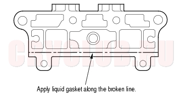
- Clean and dry the No. 5 rocker shaft holder mating surface.
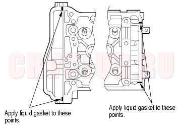
- Apply liquid gasket, P/N 08C70-K0234M, 08C70-K0334M or 08C70-X0331S, evenly to the cylinder head mating surface of the No. 5 rocker shaft holder.
- NOTE: Do not install the parts if 5 minutes or more have elapsed since applying liquid gasket. Instead, reapply liquid gasket after removing old residue.
- Reassembly the rocker arm assembly (see page 06-28) .
- Insert the bolts (A) into the rocker shaft holder, then install the rocker arm assembly (B) on the cylinder head.
- Remove the bolts from the rocker shaft holder.
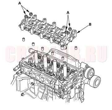
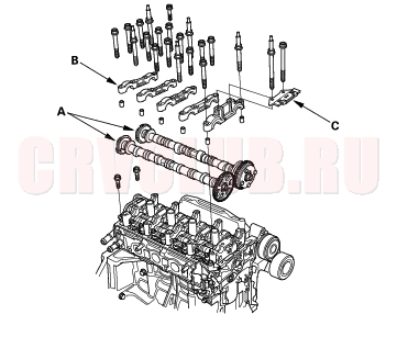
- Punch marks on the Variable Valve Timing Control (VTC) actuator and exhaust camshaft sprocket are facing up, then set the camshafts (A) in the holder.
- Set the camshaft holders (B) and cam chain guide B (C) in place.
- Tighten the bolts to the specified torque.
Specified torque:
8 mm bolts: 22 N·m (2.2 kgf·m, 16 lbf·ft)
6 mm bolts: 12 N·m (1.2 kgf·m, 8.7 lbf·ft)
6 mm bolts: 21, 22, 23
- Install the cam chain (see page 06-15) , and adjust the valve clearance (see page 06-9) .
Cylinder Head Installation06-40
Install the cylinder head in the reverse order of removal:
- Clean the cylinder head and block surface.
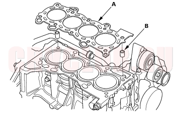
- Install the new cylinder head gasket (A) and dowel pins (B) on the cylinder block. Always use a new cylinder head gasket.
- Set the crankshaft to Top Dead Center (TDC). Align the TDC mark (A) on the crankshaft sprocket with the pointer (B) on the cylinder block.
- Install the cylinder head on the block.
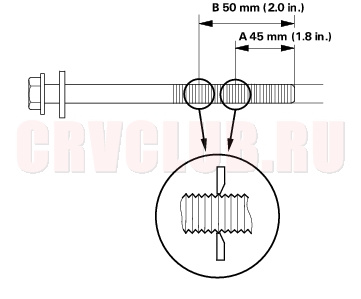
- Measure the diameter of each cylinder head bolt at point A and point B.
- If either diameter is less than 10.6 mm (0.42 in.), replace the cylinder head bolt.
06-41
- Apply engine oil to the bolt threads and under the bolt heads of all the cylinder head bolts.
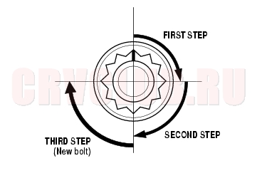
- Tighten the cylinder head bolts in sequence to 39 N·m (4.0 kgf·m, 29 lbf·ft). Use a beam-type torque wrench. When using a preset-type torque wrench, be sure to tighten slowly and do not overtighten. If a bolt makes any noise while you are torquing it, loosen the bolt and retighten it from the first step.
- After torquing, tighten all cylinder head bolts in two steps (90° per step). If you are using a new cylinder head bolt, tighten the bolt an extra 90°.
- Install the rocker arm assembly (see page 06-39) .
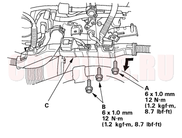
- Tighten the connecting pipe mounting bolt (A) and brake booster vacuum line mounting bolts (B), then install the harness holder (C) on the bracket.
- Install the upper radiator hose (A) and heater hose (B).
Cylinder Head Installation (cont'd)06-42
- Install the water bypass hose.
- Install the intake manifold (see page 09-5) .
- Install the exhaust manifold (see page 09-8) .
- Install the cam chain (see page 06-15) .
- Connect the fuel feed hose (see page 11-156) .
- Adjust the valve clearance (see page 06-9) .
- Install the drive belt (see page 04-30) .
- Clean the battery posts and cable terminals with sandpaper, then assemble them and apply grease to prevent corrosion.
- After installation, check that all tubes, hoses and connectors are installed correctly.
- Inspect for fuel leaks. Turn the ignition switch ON (II) (do not operate the starter) so that the fuel pump runs for about 2 seconds and pressurizes the fuel line. Repeat this operation two or three times, then check for fuel leakage at any point in the fuel line.
- Refill the radiator with engine coolant, and bleed air from the cooling system with the heater valve open (see page 10-6) .
- Inspect the idle speed (see page 11-148) .
- Inspect the ignition timing (see page 04-20) .
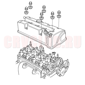
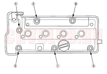
Cylinder Head Cover Installation06-42
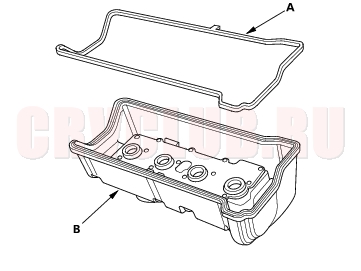
- Thoroughly clean the head cover gasket and the groove.
- Install the head cover gasket (A) in the groove of the cylinder head cover (B).
- Check that the mating surfaces are clean and dry.
- Apply liquid gasket, P/N 08C70-K0234M, 08C70-K0334M or 08C70-X0331S on the chain case and the No. 5 rocker shaft holder mating areas.
- NOTE: Do not install the parts if 5 minutes or more have elapsed since applying liquid gasket. Instead, reapply liquid gasket after removing old residue.
06-43
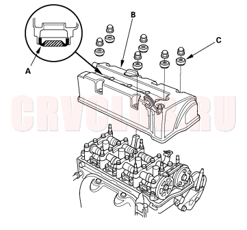
- Set the spark plug seals (A) on the spark plug tubes. Once the cylinder head cover (B) is on the cylinder head, slide the cover slightly back and forth to seat the head cover gasket.
- Inspect the cover washers (C). Replace any washer that is damaged or deteriorated.
- Tighten the bolts in two or three steps. In the final step, tighten all bolts, in sequence, to 12 N·m (1.2 kgf·m, 8.7 lbf·ft).
- Install the dipstick (A) and breather hose (B).
- Tighten the bolt (C) securing the power steering hose bracket.
Cylinder Head Cover Installation (cont'd)06-44
- Install the four ignition coils (see page 04-21) .
- Check that all tubes, hoses, and connectors are installed correctly.
- Install the intake manifold cover.
- After assembly, wait at least 30 minutes before filling the engine with oil.
|
Engine Mechanical06-1
Cylinder Head06-2 |