Engine Assembly05-2
|
Engine Mechanical05-1
Engine Assembly05-2 |
Engine Assembly05-2
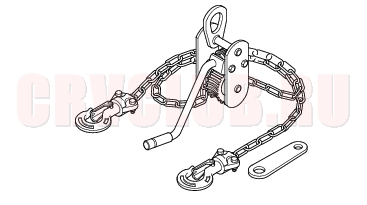
Special Tools
07KAK-SJ40101 Engine Tilt Hanger Set 1
Engine Removal05-3
Special Tools Required
Engine tilt hanger set 07KAK-SJ40101
Use fender covers to avoid damaging painted surfeces. To avoid damage, unplug the wiring connectors carefully while holding the connector portion. Mark all wiring and hoses to avoid misconnection. Also, be sure that they do not contact other wiring or hoses, or interfere with other parts.
- Secure the hood in the wide open position (support rod in the lower hole).
- Disconnect the negative cable from the battery first, then the positive cable.
- Remove the battery.
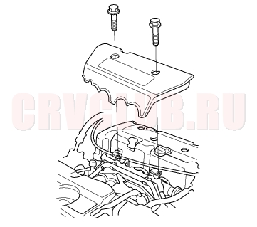
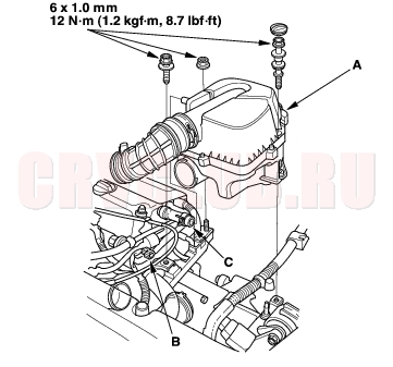
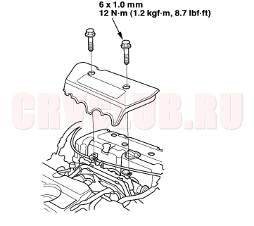
- Remove the intake manifold cover.
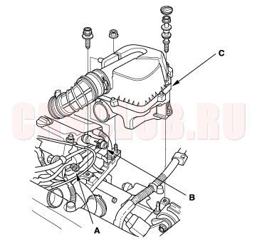
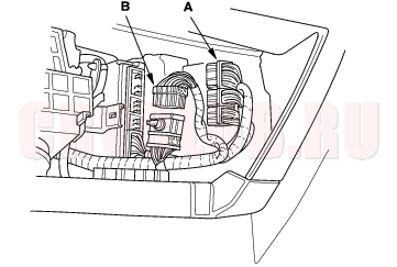
- Disconnect the Intake Air Temperature (IAT) sensor connector (A), and remove the breather hose (B), then remove the air cleaner housing (C).
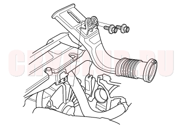
- Remove the intake air duct.
Engine Removal (cont'd)05-4
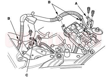
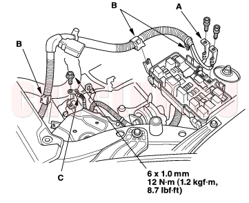
- Remove the battery cables (A) from the under-hood fuse/relay box, then remove the harness clamps (B) and ground cable (C).
- Remove the throttle cover (A). Fully open the throttle link and cruise control link by hand, then remove the throttle cable (B) and cruise control cable (C) from the links. Loosen the locknuts (D), and remove the cables from the bracket.
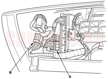
- Disconnect the Engine Control Module (ECM)/Powertrain Control Module (PCM) connectors (A) and main wire harness connector (B).
05-5
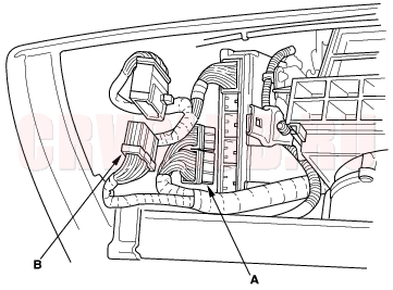
- Remove the harness clamps (A) and grommet (B), then pull the engine wire harness through the bulkhead.
- Relieve fuel pressure (see page 11-153) .
- Disconnect the fuel feed hose (see page 11-161) .
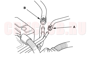
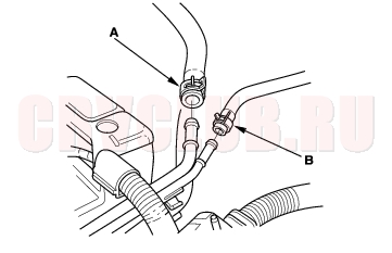
- Remove the Evaporative Emission (EVAP) canister hose (A) and brake booster vacuum hose (B).
- Remove the clutch slave cylinder and clutch line bracket (M/T) (see page 12-6) .
- Remove the shift cable and select cable (M/T) (see step 7 on page 13-5 ).
- Remove the drive belt (see page 04-30) .
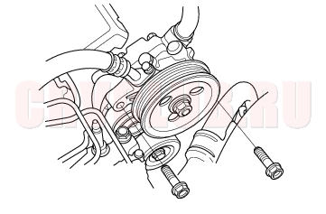
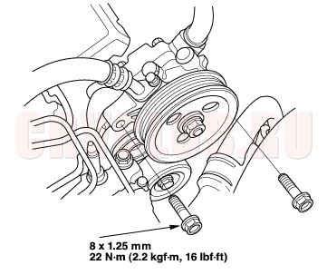
- Remove the Power Steering (P/S) pump without disconnecting the P/S hoses.
Engine Removal (cont'd)05-6
- Remove the radiator cap.
- Raise the hoist to full height.
- Remove the front tires/wheels.
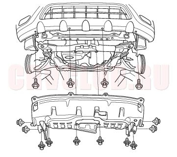
- Remove the splash shield.
- Loosen the drain plug in the radiator, drain the engine coolant (see page 10-6) .
- Drain the transmission fluid:
- Manual transmission (see page 13-4) .
- Automatic transmission (see page 14-131) .
- Drain the engine oil (see page 08-5) .
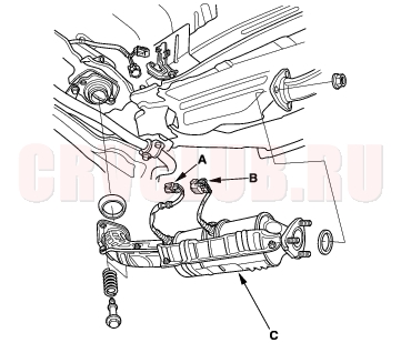
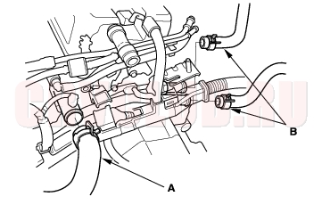
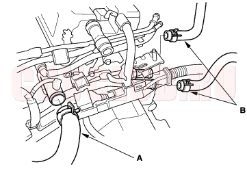
- Disconnect the primary Heated Oxygen Sensor (primary HO2S) connector (A) (Except K20A5 engine).
- Disconnect the secondary Heated Oxygen Sensor (secondary HO2S) connector (B) (KE, KG, KS, KR, KU, KZ, KQ, FO models).
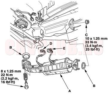
- Remove the Three Way Catalytic Converter (TWC) assembly (C) (K20A4, K24A1 engines) or exhaust chamber (C) (K20A5 engine).
- Separate the propeller shaft from the transfer (4WD models) (see page 13-64) .
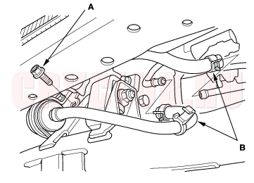
- Disconnect the stabilizer links (see page 18-18) .
- Disconnect the suspension lower arm ball joints (see page 18-20) .
- Remove the driveshafts (see page 16-3) . Coat all precision finished surfaces with clean engine oil. Tie plastic bags over the driveshaft ends.
- Remove the shift cable (A/T) (see page 14-157) .
05-7
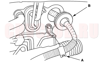
- Remove the lower hose.
- Remove the ATF filter mounting bolt (A) (A/T).
- Remove the ATF cooler hoses (B), then plug the ATF cooler hoses and lines (A/T).
- Lower the hoist.
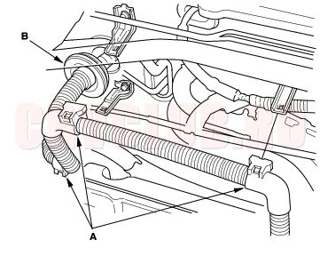
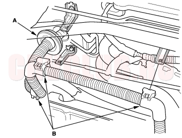
- Remove the upper hose (A) and heater hoses (B).
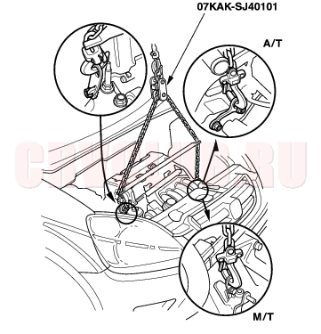
- Attach the engine tilt hanger set (Commercially available tool for EU models) to the engine as shown.
Engine Removal (cont'd)05-8
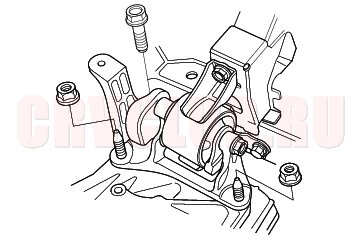
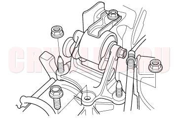
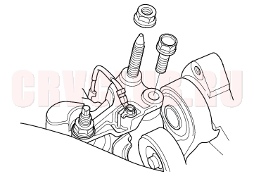
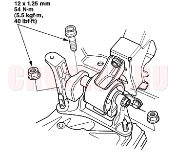
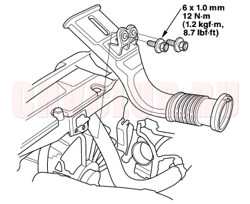
- Remove the upper bracket mounting bolt and nut.
- Make sure the hoist brackets are positioned properly. Raise the hoist to full height.
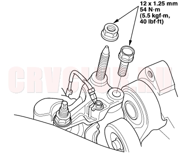
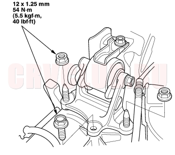
- Remove the rear mount mounting bolts.
05-9
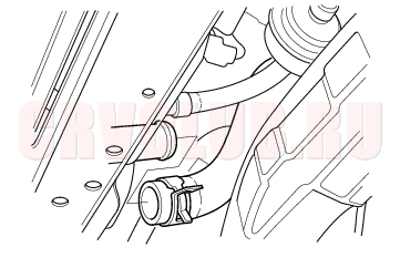
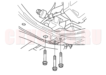
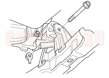
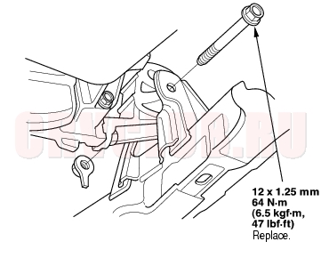
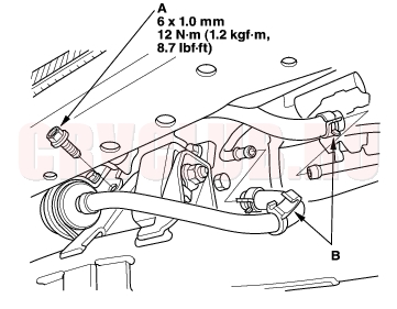
- Remove the front mount mounting bolt.
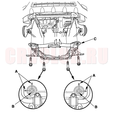
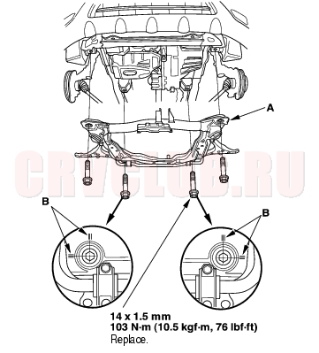
- Use a marker to make alignment marks on the reference lines (A) that align with the centers of the rear sub-frame mounting bolts (B).
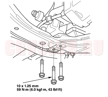
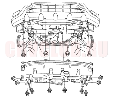
- Remove the front sub-frame (C).
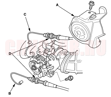
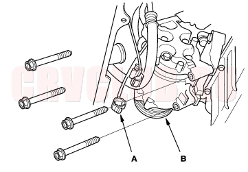
- Disconnect the compressor clutch connector (A), then remove the A/C compressor (B) without disconnecting the A/C hoses.
- Check that the engine/transmission is completely free of vacuum hoses, fuel and coolant hoses, and electrical wiring.
- Slowly lower the engine about 150 mm (6 in.). Check once again that all hoses and wires are disconnected from the engine/transmission.
- Lower the engine all the way. Remove the chain hoist from the engine.
- Remove the engine from under the vehicle.
Engine Installation05-10
05-11
- Position the engine under the vehicle. Attach the chain hoist to the engine, then lift the engine into position in the vehicle.
NOTICE
Reinstall the mounting bolts/support nuts in the sequence given. Failure to follow this sequence may cause excessive noise and vibration, and reduce bushing life.
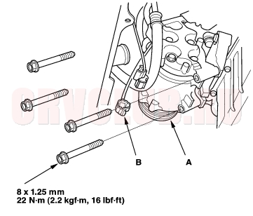
- Install the A/C compressor (A), and connect the compressor clutch connector (B).
- Install the sub-frame (A). Align the reference lines (B) on the sub-frame with the bolt head center, then tighten the bolts.
- Tighten the front mount mounting bolt.
Engine Installation (cont'd)05-12
- Tighten the rear mount mounting bolts.
- Lower the hoist.
- Tighten the upper bracket mounting bolt and nut.
- Tighten the transmission mount bracket support bolt/nuts.
05-13
- Remove the chain hoist from the engine.
- Raise the hoist to full height.
- Install a new set ring on the end of each driveshaft, then install the driveshafts. Make sure each ring ''clicks'' into place in the differential and intermediate shaft.
- Connect the suspension lower arm ball joints (see page 18-20) .
- Connect the stabilizer links (see page 18-18) .
- Install the propeller shaft to the transfer (4WD) (see step 3 on (see page 13-64) ).
- Install the shift cable (A/T) (see page 14-157) .
- Install Three Way Catalytic Converter (TWC) assembly (A) (K20A4, K24A1 engines) or exhaust chamber (A) (K20A5 engine); use new gaskets (B) and new self locking nuts (C).
- Connect the primary Heated Oxygen Sensor (primary HO2S) connector (D) (Except K20A5 engine).
- Connect the secondary Heated Oxygen Sensor (secondary HO2S) connector (E) (KE, KG, KS, KR, KU, KZ, KQ, FO models)
- Install the lower radiator hose.
- Tighten the Automatic Transmission Fluid (ATF) filter mounting bolt (A), and install the ATF cooler hoses (B) (A/T).
Engine Installation (cont'd)05-14
- Install the splash shield.
- Lower the hoist.
- Install the upper radiator hose (A) and heater hoses (B).
- Install the Power Steering (P/S) pump.
- Install the drive belt.
- Install the throttle cable (see page 11-184) , then adjust the cable (see page 11-183) .
- Install the cruise control cable, then adjust the cable (see page 04-49) .
05-15
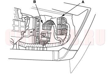
- Push the Engine Control Module (ECM)/Power train Control Module (PCM) connectors through the bulkhead, then install the grommet (A).
- Install the harness clamps (B).
- Connect the ECM/PCM connectors (A) and main wire harness connector (B).
Engine Installation (cont'd)05-16
- Install the brake booster vacuum hose (A) and the Evaporative Emission (EVAP) canister hose (B).
- Connect the fuel feed hose (see page 11-162) .
- Install the select cable and shift cable (M/T) (see step 25 on page 13-14 ).
- Install the clutch slave cylinder and clutch line bracket (M/T) (see step 24 on page 13-14 ).
- Install the battery cables (A) on the under-hood fuse/relay box, then install the harness clamps (B).
- Install the ground cable (C).
- Install the intake air duct.
05-17
- Install the air cleaner housing (A) and connect the Intake Air Temperature (IAT) sensor connector (B).
- Install the breather hose (C).
- Install the intake manifold cover.
- Install the battery. Clean the battery posts and cable terminals with sandpaper, then assemble them and apply grease to prevent corrosion.
- Move the shift lever to each gear, and verify that the A/T gear position indicator follows the transmission range switch (A/T).
- Check that the transmission shifts into gear smoothly (M/T).
- Inspect for fuel leaks. Turn the ignition switch ON (II) (do not operate the starter) so that the fuel pump runs for about 2 seconds and pressurizes the fuel line. Repeat this operation two or three times, then check for fuel leakage at any point in the fuel line.
- Refill the engine with engine oil (see page 08-5) .
- Refill the transmission with fluid:
- Manual transmission (see page 13-4) .
- Automatic transmission (see page 14-131) .
- Refill the radiator with engine coolant, and bleed air from the cooling system with the heater valve open (see page 10-6) .
- Inspect the idle speed (see page 11-148) .
- Inspect the ignition timing (see page 04-20) .
- Check the wheel alignment (see page 18-4) .
|
Engine Mechanical05-1
Engine Assembly05-2 |