Air Conditioning21-31
|
HVAC 21-1
Air Conditioning21-31 |
Air Conditioning21-31
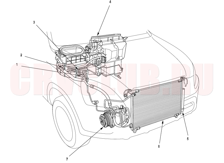
Component Location Index
NOTE: LHD type is shown, RHD type is similar.
Replacement, page 21-45 Replacement, page 21-51 Replacement, page 21-46 ; Clutch Check, page 21-47 ; Clutch Overhaul, page 21-48 ; Thermal Protector Check, page 21-47 ; Thermal Protector Replacement, page 21-50 ; Relief Valve Replacement, page 21-50
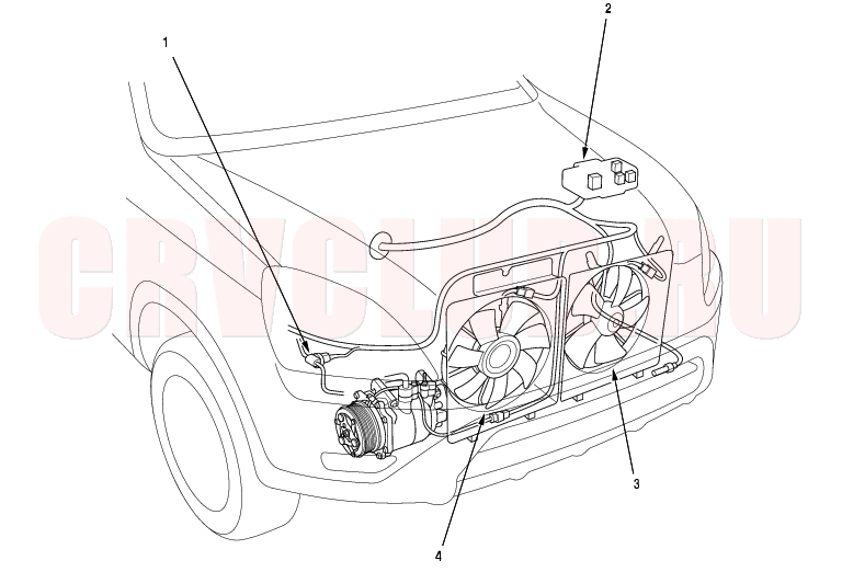
Component Location Index (cont'd)21-32
NOTE: LHD type is shown, RHD type is similar.
BLOWER MOTOR RELAY, RADIATOR FAN RELAY, CONDENSER FAN RELAY, COMPRESSOR CLUTCH RELAY
Test, page 22A-60
A/C Service Tips and Precautions21-33
Air conditioning refrigerant or lubricant vapor can irritate your eyes, nose, or throat. Be careful when connecting service equipment. Do not breathe refrigerant or vapor.
The air conditioning system uses HFC-134a (R-134a) refrigerant and polyalkyleneglycol (PAG) refrigerant oil, which are not compatible with CFC-12 (R-12) refrigerant and mineral oil. Do not use R-12 refrigerant or mineral oil in this system, and do not attempt to use R-12 servicing equipment; damage to the air conditioning system or your servicing equipment will result.
Separate the manifold gauge sets (pressure gauges, hoses, joints) for refrigerants R-12 and R-134a. Do not confuse them.
If accidental system discharge occurs, ventilate work area before resuming service.
R-134a service equipment or vehicle air conditioning systems should not be pressure tested or leak tested with compressed air.
Additional health and safety information may be obtained from the refrigerant and lubricant manufacturers.
Always disconnect the negative cable from the battery whenever replacing air conditioning parts. Keep moisture and dirt out of the system. When disconnecting any lines, plug or cap the fittings immediately; don't remove the caps or plugs until just before you reconnect each line. Before connecting any hose or line, apply a few drops of refrigerant oil to the O-ring. When tightening or loosening a fitting, use a second wrench to support the matching fitting. When discharging the system, don't let refrigerant escape too fast; it will draw the compressor oil out of the system. A/C Refrigerant Oil Replacement21-33
P/N 38897-P13-003: 120 ml (4 fl·oz, 4.2 lmp·oz) P/N 38898-P13-003: 250 ml (8 1/3 fl·oz, 8.8 lmp·oz) P/N 38899-P13-A01: 40 ml (1 1/3 fl·oz, 1.4 lmp·oz) Add the recommended refrigerant oil in the amount listed if you replace any of the following parts.
To avoid contamination, do not return the oil to the container once dispensed, and never mix it with other refrigerant oils. Immediately after using the oil, reinstall the cap on the container, and seal it to avoid moisture absorption. Do not spill the refrigerant oil on the vehicle; it may damage the paint; if it gets on the paint, wash it off immediately. Condenser 35 ml (1 1/6 fl·oz, 1.2 lmp·oz)
Front evaporator 40 ml (1 1/3 fl·oz, 1.4 lmp·oz)
Rear evaporator 30 ml (1 fl·oz, 1.1 lmp·oz)
Line or hose 10 ml (1/3 fl·oz, 0.4 lmp·oz)
Leakage repair 25 ml (5/6 fl·oz, 0.9 lmp·oz)
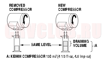
Compressor For compressor replacement, subtract the volume of oil drained from the removed compressor from A, and drain the calculated volume of oil from the new compressor: A - Volume of removed compressor = Volume to drain from new compressor.
NOTE: Even if no oil is drained from the removed compressor, don't drain more than 50 ml (1 2/3 fl·oz, 1.8 lmp·oz) from the new compressor.
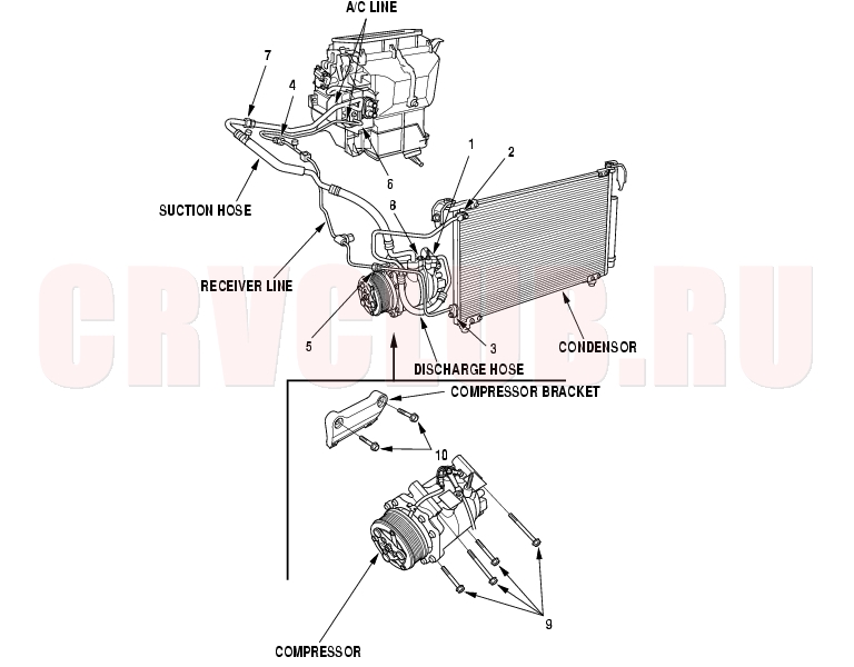
A/C Refrigerant Oil Replacement (cont'd)21-34
NOTE: LHD type is shown, RHD type is similar.
Symptom Troubleshooting Index21-35
Condenser fan does not run at all (but radiator fan runs with the A/C on) Condenser Fan Circuit Troubleshooting (see page 21-38) Blown fuse No. 1 (20A) in the under-hood fuse/relay box, and No. 14 (10A) in the under-dash fuse/relay box Poor ground at G201 Cleanliness and tightness of all connectors Both fans do not run with the A/C on Radiator and Condenser Fans Common Circuit Troubleshooting (see page 21-39) Blown fuse No. 1 (20A) and No. 4 (20A) in the under-hood fuse/relay box, and No. 14 (10A) in the under-dash fuse/relay box Poor ground at G201 Cleanliness and tightness of all connectors Compressor clutch does not engage Compressor Clutch Circuit Troubleshooting (see page 21-40) Blown fuse No. 1 (20A) in the under-hood fuse/relay box, and No. 14 (10A) in the under-dash fuse/relay box Cleanliness and tightness of all connectors A/C System does not come on (both fans and compressor) A/C Pressure Switch Circuit Troubleshooting (see page 21-42) Cleanliness and tightness of all connectors
System Description21-36
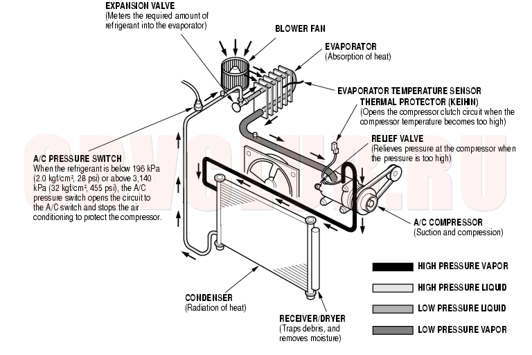
The air conditioning system removes heat from the passenger compartment by circulating refrigerant through the system as shown below.
This vehicle uses HFC-134a (R-134a) refrigerant which does not contain chlorofluorocarbons. Pay attention to the following service items:
Do not mix refrigerants CFC-12 (R-12) and HFC-134a (R-134a). They are not compatible. Use only the recommended polyalkyleneglycol (PAG) refrigerant oil (KEIHIN SP-10) designed for the R-134a compressor. Intermixing the recommended (PAG) refrigerant oil with any other refrigerant oil will result in compressor failure. All A/C system parts (compressor, discharge line, suction line, evaporator, condenser, receiver/dryer, expansion valve,
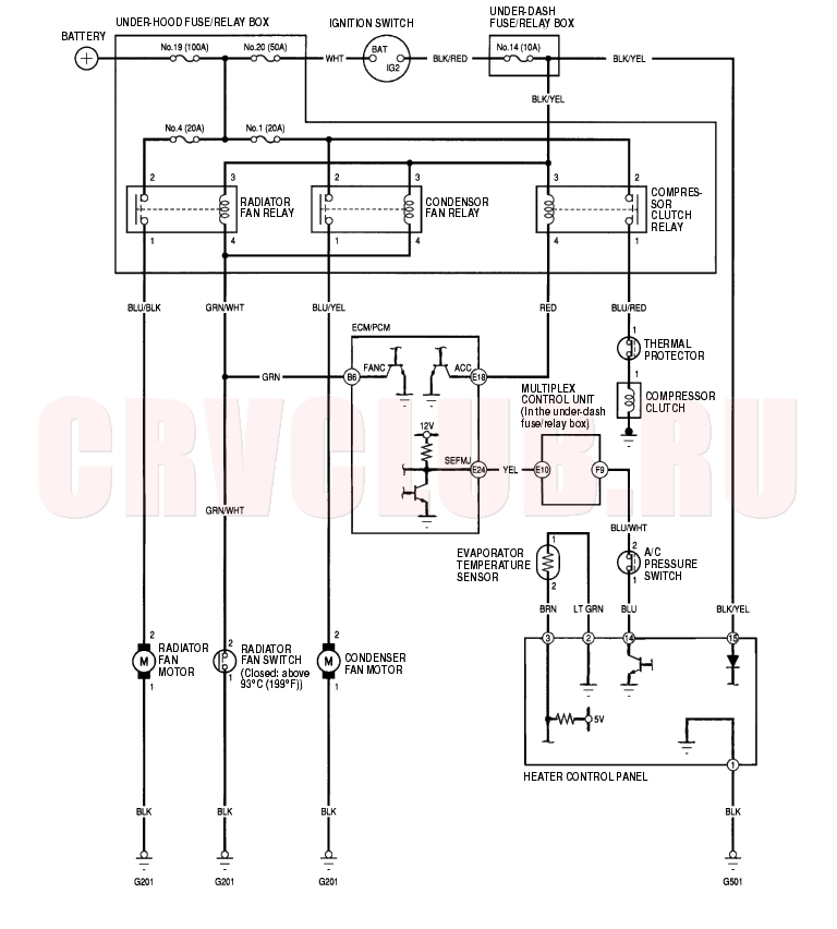
O-rings for joints) have to be proper for refrigerant R-134a. Do not confuse with R-12 parts.Use a halogen gas leak detector designed for refrigerant R-134a. Use a vacuum pump adapter which is equipped with a check valve to prevent the backflow of the vacuum pump oil. Separate the manifold gauge sets (pressure gauges, hoses, joints) for refrigerants R-12 and R-134a. Do not confuse them. Circuit Diagram21-37
Condenser Fan Circuit Troubleshooting21-38
- Check the No. 1 (20A) fuse in the under-hood fuse/relay box, and the No. 14 (10A) fuse in the under-dash fuse/relay box.
Are the fuses OK?
Yes : Go to step 2.
No : Replace the fuse(s), and recheck.

- Remove the condenser fan relay from the under-hood fuse/relay box, and test it (see page 22A-60) .
Is the relay OK?
Yes : Go to step 3.
No : Replace the condenser fan relay.
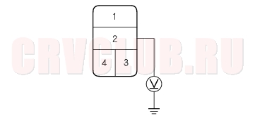
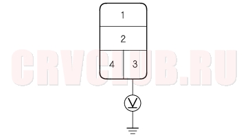
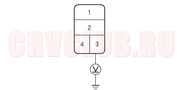
- Measure the voltage between the No. 2 terminal of the condenser fan relay 4P socket and body ground.
Is there battery voltage?
Yes : Go to step 4.
No : Replace the under-hood fuse/relay box.
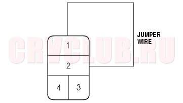
Does the condenser fan run?
Yes : Go to step 5.
No : Go to step 8.
- Disconnect the jumper wire.
- Turn the ignition switch ON (II).
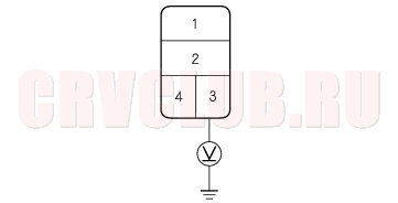
- Measure the voltage between the No. 3 terminal of the condenser fan relay 4P socket and body ground.
Is there battery voltage?
Yes : Replace the under-hood fuse/relay box.
No : Repair open in the wire between the No. 14 fuse in the under-dash fuse/relay box and the condenser fan relay socket in the under-hood fuse/relay box.
21-39
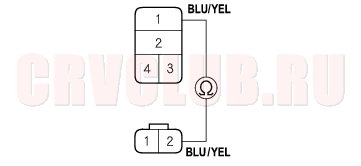
- Disconnect the condenser fan 2P connector.
- Check for continuity between the No. 1 terminal of the condenser fan relay 4P socket and the No. 2 terminal of the condenser fan 2P connector.
Is there continuity?
Yes : Go to step 11.
No : Repair open in the wire between the condenser fan relay socket in the under-hood fuse/relay box and the condenser fan.
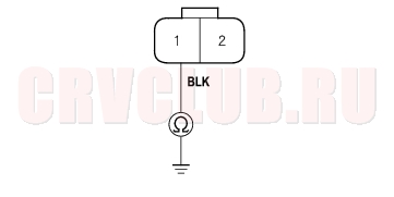
Is there continuity?
Yes : Replace the condenser fan motor.
No : Check for an open in the wire between the condenser fan and body ground. If the wire is OK, check for poor ground at G201.
Radiator and Condenser Fans Common Circuit Troubleshooting21-39
- Check the No. 1 (20A) and No. 4 (20A) fuses in the under-hood fuse/relay box, and the No. 14 (10A) fuse in the under-dash fuse/relay box.
Are the fuses OK?
Yes : Go to step 2.
No : Replace the fuse(s), and recheck.
- Remove the condenser fan relay from the under-hood fuse/relay box.
- Turn the ignition switch ON (II).
- Measure the voltage between the No. 3 terminal of the condenser fan relay 4P socket and body ground.
Is there battery voltage?
Yes : Go to step 5.
No : Repair open in the wire between the No. 14 fuse in the under-dash fuse/relay box and the radiator fan relay socket, and the condenser fan relay socket.
- Turn the ignition switch OFF.
- Reinstall the condenser fan relay.
- Make sure the A/C switch is OFF.
- Turn the ignition switch ON (II).
Radiator and Condenser Fans Common Circuit Troubleshooting (cont'd)21-40
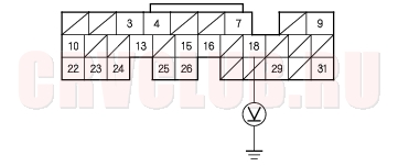
- Measure the voltage between the No. 6 terminal of ECM/PCM connector B (24P) and body ground with the ECM/PCM connectors connected.
Is there battery voltage?
Yes : Check for loose wires or poor connections at ECM/PCM connector B (24P). If the connections are good, substitute a known-good ECM/PCM, and recheck. If the symptom/indication goes away, replace the original ECM/PCM.
No : Repair open in the wire between the radiator fan relay socket, the condenser fan relay socket and the ECM/PCM.
Compressor Clutch Circuit Troubleshooting21-40
- Check the No. 1 (20A) fuse in the under-hood fuse/relay box, and the No. 14 (10A) fuse in the under-dash fuse/relay box.
Are the fuses OK?
Yes : Go to step 2.
No : Replace the fuse(s), and recheck.
Is the coolant temperature above nomal?
Yes : Troubleshoot and repair the cause of the high engine coolant temperature.
No : Go to step 3.
- Remove the compressor clutch relay from the under-hood fuse/relay box, and test it (see page 22A-60) .
Is the relay OK?
Yes : Go to step 4.
No : Replace the compressor clutch relay.
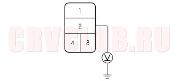
- Measure the voltage between the No. 2 terminal of the compressor clutch relay 4P socket and body ground.
Is there battery voltage?
Yes : Go to step 5.
No : Replace the under-hood fuse/relay box.
21-41
Does the compressor clutch click ?
Yes : Go to step 6.
No : Go to step 14.
- Disconnect the jumper wire.
- Turn the ignition switch ON (II).
- Measure the voltage between the No. 3 terminal of the compressor clutch relay 4P socket and body ground.
Is there battery voltage?
Yes : Go to step 9.
No : Repair open in the wire between the No. 14 fuse in the under-dash fuse/relay box and the compressor clutch relay socket.
- Turn the ignition switch OFF.
- Reinstall the compressor clutch relay.
- Make sure the A/C switch is OFF.
- Turn the ignition switch ON (II).
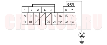
- Measure the voltage between the No. 18 terminal of ECM/PCM connector E (31P) and body ground with the ECM/PCM connectors connected.
Is there battery voltage?
Yes : Check for loose wires or poor connections at ECM/PCM connector E (31P). If the connections are good, substitute a known-good ECM/PCM, and recheck. If the symptom/indication goes away, replace the original ECM/PCM.
No : Repair open in the wire between the compressor clutch relay and the ECM/PCM.
Compressor Clutch Circuit Troubleshooting (cont'd)21-42
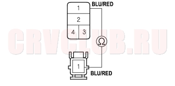
- Check for continuity between the No. 1 terminal of the compressor clutch relay 4P socket and the No. 1 terminal of the compressor clutch 1P connector.
Is there continuity?
Yes : Check the KEIHIN compressor clutch clearance, the thermal protector, and the compressor clutch field coil (see page 21-47).
No : Repair open in the wire between the compressor clutch relay socket and the compressor clutch.
A/C Pressure Switch Circuit Troubleshooting21-42
Does the blower motor run on all speeds?
Yes : Go to step 3.
No : Troubleshoot the blower motor circuit (see page 21-13).
- Disconnect the A/C pressure switch 2P connector.
- Turn the ignition switch ON (II).
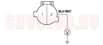
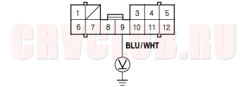
- Measure the voltage between the No. 2 terminal of the A/C pressure switch 2P connector and body ground.
Is there 5V or more?
Yes : Go to step 6.
No : Go to step 12.
21-43
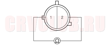
Is there continuity?
Yes : Go to step 8.
No : Go to step 14.
- Reconnect the A/C pressure switch 2P connector.
- Disconnect the heater control panel 30P connector.
- Turn the ignition switch ON (II).
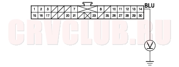
- Measure the voltage between the No. 14 terminal of the heater control panel 30P connector and body ground.
Is there battery voltage?
Yes : Check for loose wires or poor connections at the heater control panel 30P connector and at the A/C pressure switch 2P connector. If the connections are good, substitute a known-good heater control panel, and recheck. If the symptom/indication goes away, replace the original heater control panel.
No : Repair open in the wire between the heater control panel and the A/C pressure switch.
- Make sure the A/C switch is OFF.
- Measure the voltage between the No. 9 terminal of under-dash fuse/relay box connector F (12P) and body ground with the under-dash fuse/relay box connectors connected.
Is there 5 V or more?
Yes : Repair open in the wire between the under-dash fuse/relay box and the A/C pressure switch.
No : Refer to the multiplex control system (see page 22A-227).
NOTE: Check for multiplex codes in mode 1. Follow the troubleshooting for any codes found. If no codes are found, substitute a known-good multiplex control unit and a PCM one at a time. Is the pressure within specifications?
Yes : Replace the A/C pressure switch.
No : Repair the A/C pressure problem.
Evaporator Temperature Sensor Replacement21-44
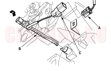
NOTE: LHD type is shown, RHD type is symmetrical.
- Disconnect the 2P connector (A) from the evaporator temperature sensor (B), then remove the connector clip (C). Turn the evaporator temperature sensor counterclockwise to the stop, and carefully pull out it.
- Install the sensor in the reverse order of removal.
Evaporator Temperature Sensor Test21-44
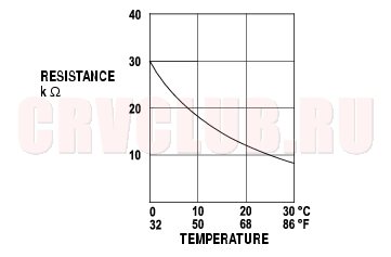
- Then pour hot water on the sensor, and check for a change in resistance.
- Compare the resistance readings with the specifications shown in the graph; the resistance should be within the specifications.
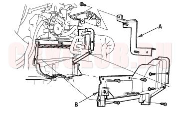
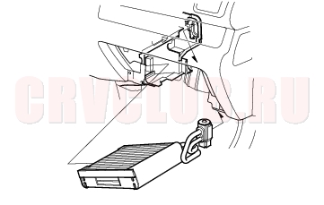
Evaporator Core Replacement21-45
NOTE: LHD type is shown, RHD type is symmetrical.
- Recover the refrigerant with a recovery/recycling/charging station (see page 21-53) .
- Remove the bolt, then disconnect the A/C line from the evaporator core.
- Remove the blower unit (see page 21-26) .
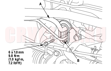
- Remove the bolt and the ECM/PCM bracket (A). Remove the self-tapping screws and the expansion valve cover (B).
- Carefully pull out the evaporator core without bending the pipes.
- Install the core in the reverse order of removal, and note these items:
- If you're installing a new evaporator core, add refrigerant oil (KEIHIN SP-10) (see page 21-33) .
- Replace the O-rings with new ones at each fitting, and apply a thin coat of refrigerant oil before installing them. Be sure to use the right O-rings for HFC-134a (R-134a) to avoid leakage.
- Immediately after using the oil, reinstall the cap on the container, and seal it to avoid moisture absorption.
- Do not spill the refrigerant oil on the vehicle; it may damage the paint; if the refrigerant oil contacts the paint, wash it off immediately.
- Charge the system (see page 21-55) .
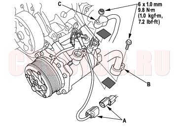
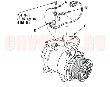
Compressor Replacement21-46
- If the compressor is marginally operable, run the engine at idle speed, and let the air conditioning work for a few minutes, then shut the engine off.
- Disconnect the negative cable from the battery.
- Recover the refrigerant with a recovery/recycling/charging station (see page 21-53) .
- Remove the radiator reservoir tank (see page 10-10) .
- Remove the alternator (see page 04-32) .
- Disconnect the compressor clutch connector (A), remove the bolt and nut, then disconnect the suction line (B) and the discharge line (C) from the compressor. Plug or cap the lines immediately after disconnecting them to avoid moisture and dust contamination.
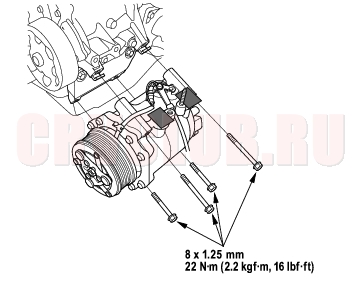
- Remove the mounting bolts and the compressor. Be careful not to damage the radiator fins when removing the compressor.
- Install the compressor in the reverse order of removal, and note these items:
- If you're installing a new compressor, you must calculate the amount of refrigerant oil to be removed from it (see page 21-33) .
- Replace the O-rings with new ones at each fitting, and apply a thin coat of refrigerant oil before installing them. Be sure to use the right O-rings for HFC-134a (R-134a) to avoid leakage.
- Use refrigerant oil (KEIHIN SP-10) for HFC-134a KEIHIN spiral type compressor only.
- To avoid contamination, do not return the oil to the container once dispensed, and never mix it with other refrigerant oils.
- Immediately after using the oil, reinstall the cap on the container, and seal it to avoid moisture absorption.
- Do not spill the refrigerant oil on the vehicle; it may damage the paint; if the refrigerant oil contacts the paint, wash it off immediately.
- Be careful not to damage the radiator fins when installing the compressor and the condenser fan shroud.
- Charge the system (see page 21-55)
- Enter the anti-theft code for the radio, then enter the customer's radio station presets.
Compressor Clutch Check21-47
- Check the armature plate for discoloration, peeling, or other damage. If there is damage, replace the clutch set (see page 21-48) .
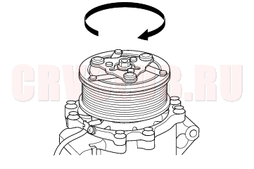
- Check the rotor pulley bearing play and drag by rotating the rotor pulley by hand. Replace the clutch set with a new one if it is noisy or has excessive play/drag (see page 21-48) .
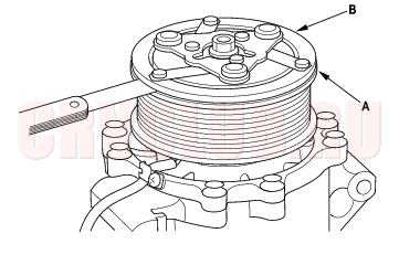
- Measure the clearance between the rotor pulley (A) and the armature plate (B) all the way around. If the clearance is not within specified limits, remove the armature plate (see page 21-48) and add or remove shims as needed to increase or decrease clearance.
Clearance: 0.5 ± 0.15 mm (0.020 ± 0.006 in.)
NOTE: The shims are available in four thicknesses: 0.1 mm, 0.2 mm, 0.4 mm, and 0.5 mm.
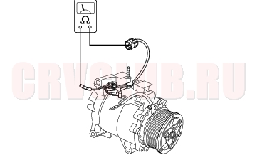
- Release the field coil connector from the holder, then disconnect it. Check the thermal protector for continuity. If there is no continuity, replace the thermal protector (see page 21-50) .
- NOTE: The thermal protector will have no continuity above 122 to 128°C (252 to 262°F). When the temperature drops below 116 to 104°C (241 to 219°F), the thermal protector will have continuity.
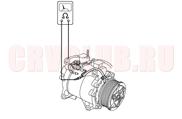
- Check resistance of the field coil. If resistance is not within specifications, replace the field coil
(see page 21-48) .
Field Coil Resistance: 3.05 - 3.35 ohms at 20°C
(68°F)
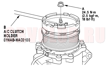
Compressor Clutch Overhaul21-48
- Remove the center nut (A) while holding the armature plate with the special tool (B).
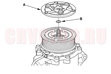
- Remove the armature plate (A) and shim(s) (B), taking care not to lose the shim(s). If the clutch needs adjustment, increase or decrease the number and thickness of shims as necessary, then reinstall the armature plate, and recheck its clearance (see page 21-47) .
- NOTE: The shims are available in four thickness: 0.1 mm, 0.2 mm, 0.4 mm and 0.5 mm.
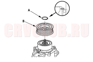
- If you are replacing the field coil, remove the snap ring (A) with snap ring pliers, then remove the rotor pulley (B). Be careful not to damage the rotor pulley and compressor.
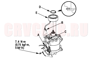
- Remove the bolt and holder (A), then disconnect the field coil connector (B). Loosen the clamp screw (C) to free the field coil wire. Remove the snap ring (D) with snap ring pliers, then remove the field coil (E). Be careful not to damage the field coil and compressor.
21-49
- Reassemble the clutch in the reverse order of disassembly, and note these items:
- Install the field coil with the wire side facing down, and align the boss on the field coil with the hole in the compressor.
- Clean the rotor pulley and compressor sliding surfaces with contact cleaner or other non-petroleum solvent.
- Install new snap rings, note the installation direction, and make sure they are fully seated in the groove.
- Make sure that the rotor pulley turns smoothly after it's reassembled.
- Route and clamp the wires properly or they can be damaged by the rotor pulley.
Compressor Thermal Protector Replacement21-50
- Remove the bolt, the ground terminal (A), and the holder (B). Disconnect the field coil connector (C), then remove the thermal protector (D).
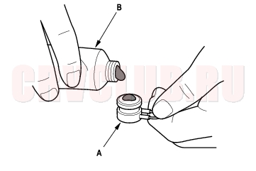
- Replace the thermal protector (A) with a new one, and apply silicone sealant (B) to the bottom of the thermal protector.
- Install in the reverse order of removal.
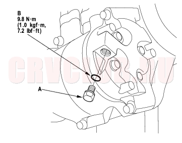
Compressor Relief Valve Replacement21-50
- Recover the refrigerant with a recovery/recycling/charging station (see page 21-53) .
- Remove the relief valve (A), and the O-ring (B). Plug the opening to keep foreign matter from entering the system and the compressor oil from running out.
- Clean the mating surfaces.
- Install a new O-ring on the relief valve, and apply a thin coat of refrigerant oil to the O-ring.
- Remove the plug, and install and tighten the relief valve.
- Charge the system (see page 21-55) .
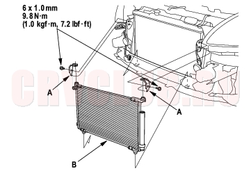
Condenser Replacement21-51
- Recover the refrigerant with a recovery/recycling/charging station (see page 21-55) .
- Remove the front bumper (see page 20-130) .
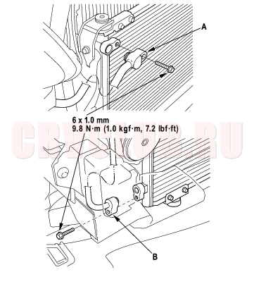
- Remove the bolts, then disconnect the discharge line (A) and the receiver line (B) from the condenser. Plug or cap the lines immediately after disconnecting them to avoid moisture and dust contamination.
- Remove the bolts and mounting brackets (A), then remove the condenser (B) by lifting it up. Be careful not to damage the radiator and condenser fins when removing the condenser.
- Install the condenser in the reverse order of removal, and note these items:
- If you're installing a new condenser, add refrigerant oil (KEIHIN SP-10) (see page 21-33) .
- Replace the O-rings with new ones at each fitting, and apply a thin coat of refrigerant oil before installing them. Be sure to use the right O-rings for HFC-134a (R-134a) to avoid leakage.
- Immediately after using the oil, reinstall the cap on the container, and seal it to avoid moisture absorption.
- Do not spill the refrigerant oil on the vehicle; it may damage the paint; if the refrigerant oil contacts the paint, wash it off immediately.
- Be careful not to damage the radiator and condenser fins when installing the condenser.
- Charge the system (see page 21-55) .
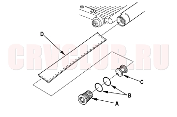
Receiver/Dryer Desiccant Replacement21-52
- Remove the condenser (see page 21-51) .
- Remove the cap (A) from the bottom of the condenser, then remove the O-rings (B), the filter (C) and the desiccant (D).
- Install the desiccant in the reverse order of removal, and note these items:
- Replace the O-rings with new ones, and apply a thin coat of refrigerant oil (KEIHIN SP-10) before installing them.
- Be sure to use the right O-rings for HFC-134a
(R-134a) to avoid leakage.Refrigerant Recovery21-53
Air conditioning refrigerant or lubricant vapor can irritate your eyes, nose, or throat. Be careful when connecting service equipment. Do not breathe refrigerant or vapor.
Use only service equipment for refrigerant HFC-134a (R-134a).
If accidental system discharge occurs, ventilate work area before resuming service.
Additional health and safety information may be obtained from the refrigerant and lubricant manufacturers.
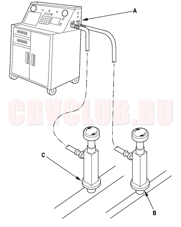
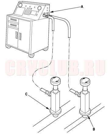
- Connect a R-134a refrigerant recovery/recycling/charging station (A) to the high-pressure service port (B) and the low-pressure service port (C), as shown, following the equipment manufacturer's instructions.
- Measure the amount of refrigerant oil removed from the A/C system after the recovery process is completed. Be sure to put the same amount of new refrigerant oil back into the A/C system before charging.
System Evacuation21-54
Air conditioning refrigerant or lubricant vapor can irritate your eyes, nose, or throat. Be careful when connecting service equipment. Do not breathe refrigerant or vapor.
Use only service equipment for refrigerant HFC-134a (R-134a).
If accidental system discharge occurs, ventilate work area before resuming service.
Additional health and safety information may be obtained from the refrigerant and lubricant manufacturers.
- When an A/C system has been opened to the atmosphere, such as during installation or repair, it must be evacuated using a R-134a refrigerant recovery/recycling/charging station. (If the system has been open for several days, the receiver/dryer should be replaced, and the system should be evacuated for several hours.)
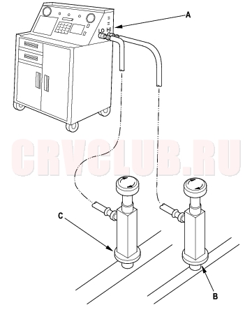
- Connect a R-134a refrigerant recovery/recycling/charging station (A) to the high-pressure service port (B) and the low-pressure service port (C), as shown, following the equipment manufacturer's instructions. Evacuate the system.
- If the low-pressure does not reach more than 93.3 kPa (700 mmHg, 27.6 in.Hg) in 15 minutes, there is probably a leak in the system. Partially charge the system, and check for leaks (see step 3 on page 21-56 ).
System Charging21-55
Use only service equipment for refrigerant HFC-134a (R-134a).
If accidental system discharge occurs, ventilate work area before resuming service.
Additional health and safety information may be obtained from the refrigerant and lubricant manufacturers.
- Connect a R-134a refrigerant recovery/recycling/charging station (A) to the high-pressure service port (B) and the low-pressure service port (C), as shown, following the equipment manufacturer's instructions.
- Evacuate the system (see page 21-54) .
- Add the same amount of new refrigerant oil to the system that was removed during recovery. Use only KEIHIN SP-10 refrigerant oil.
- Charge the system with the specified amount of
R-134a refrigerant. Do not overcharge the system; the compressor will be damaged.
- Select the appropriate units of measure for your refrigerant charging station.
Refrigerant capacity:
480 to 530 g
0.48 to 0.53 kg
1.06 to 1.17 lbs
16.9 to 18.7 oz
- Check for refrigerant leaks (see page 21-56) .
- Check for system performance (see page 21-58) .
Refrigerant Leak Test21-56
Air conditioning refrigerant or lubricant vapor can irritate your eyes, nose, or throat. Be careful when connecting service equipment. Do not breathe refrigerant or vapor.
Use only service equipment for refrigerant HFC-134a (R-134a).
If accidental system discharge occurs, ventilate work area before resuming service.
R-134a service equipment or vehicle air conditioning systems should not be pressure tested or leak tested with compressed air.
Additional health and safety information may be obtained from the refrigerant and lubricant manufacturers.
- Connect a R-134a refrigerant recovery/recycling/charging station (A) to the high-pressure service port (B) and the low-pressure service port (C), as shown, following the equipment manufacturer's instructions.
- Open high pressure valve to charge the system to the specified capacity, then close the supply valve, and remove the charging system couplers.
- Select the appropriate units of measure for your refrigerant charging station.
Refrigerant capacity:
480 to 530 g
0.48 to 0.53 kg
1.06 to 1.17 lbs
16.9 to 18.7 oz
- Check the system for leaks using a R-134a refrigerant leak detector with an accuracy of 14 g (0.5 oz) per year or better.
- If you find leaks that require the system to be opened (to repair or replace hoses, fittings, etc.), recover the system.
- After checking and repairing leaks, the system must be evacuated.
A/C System Tests21-57
Pressure Test
Discharge (high) pressure abnormally high After stopping compressor, pressure drops to about 196 kPa (2.0 kgf/cm2, 28 psi) quickly, and then falls gradually. Air in system Discharge, evacuate (see page 21- 54) , and recharge with specified amount (see page 21-55) . No bubbles in sight glass when condenser is cooled by water. Excessive refrigerant in system Discharge, evacuate, and recharge with specified amount. Reduced or no air flow through condenser. Clogged condenser or radiator fins Condenser or radiator fan not working properly Clean. Check voltage and fan rpm. Check fan direction. Line to condenser is excessively hot. Restricted flow of refrigerant in system Restricted lines Discharge pressure abnormally low Excessive bubbles in sight glass; condenser is not hot. Insufficient refrigerant in system Check for leak. Charge system. High and low pressures are balanced soon after stopping compressor. Low side is higher than normal. Faulty compressor discharge valve Faulty compressor seal Replace the compressor. Outlet of expansion valve is not frosted, low-pressure gauge indicates vacuum. Faulty expansion valve Moisture in system Replace. Discharge, evacuate, and recharge with specified amount. Suction (low) pressure abnormally low Excessive bubbles in sight glass; condenser is not hot. Insufficient refrigerant in system Repair the leaks. Discharge, evacuate, and recharge with specified amount. Charge as required. Expansion valve is not frosted, and low-pressure line is not cold. Low- pressure gauge indicates vacuum. Frozen expansion valve (Moisture in system) Faulty expansion valve Discharge, evacuate, and recharge with specified amount. Replace the expansion valve. Discharge temperature is low, and the air flow from vents is restricted. Frozen evaporator Run the fan with compressor off, then check evaporator temperature sensor. Expansion valve is frosted. Clogged expansion valve Clean or replace. Suction pressure abnormally high Low-pressure hose and check joint are cooler than the temperature around evaporator. Expansion valve open too long Repair or replace. Suction pressure is lowered when condenser is cooled by water. Excessive refrigerant in system Discharge, evacuate, and recharge with specified amount. High and low-pressure are equalized as soon as the compressor is stopped, and both gauges fluctuate while running. Faulty gasket Faulty high-pressure valve Foreign particle stuck in high-pressure valve Replace the compressor. Suction and discharge pressures abnormally high Reduced air flow through condenser. Clogged condenser or radiator fins Condenser or radiator fan not working properly Clean. Check voltage and fan rpm. Check fan direction. No bubbles in sight glass when condenser is cooled by water. Excessive refrigerant in system Discharge, evacuate, and recharge with specified amount. Suction and discharge pressure abnormally low Low-pressure hose and metal end areas are cooler than evaporator. Clogged or kinked low-pressure hose parts Repair or replace. Temperature around expansion valve is too low compared with that around receiver/dryer. Clogged high-pressure line Repair or replace. Refrigerant leaks Compressor clutch is dirty. Compressor shaft seal leaking Replace the compressor. Compressor bolt(s) are dirty. Leaking around bolt(s) Tighten bolt(s) or replace compressor. Compressor gasket is wet with oil. Gasket leaking Replace the compressor.
A/C System Tests (cont'd)21-58
Performance Test
Air conditioning refrigerant or lubricant vapor can irritate your eyes, nose, or throat. Be careful when connecting service equipment. Do not breathe refrigerant or vapor.
The performance test will help determine if the air conditioner system is operating within specifications.
Use only service equipment for refrigerant HFC-134a (R-134a).
If accidental system discharge occurs, ventilate work area before resuming service.
R-134a service equipment or vehicle air conditioning systems should not be pressure tested or leak tested with compressed air.
Additional health and safety information may be obtained from the refrigerant and lubricant manufacturers.
- Connect a R-134a refrigerant recover/recycling/charging station to the high-pressure service port and the low-pressure service port, following the equipment manufacturer's instructions.
- Insert a thermometer in the center vent.
- Test conditions:
- Avoid direct sunlight.
- Open the hood.
- Open the front doors.
- Set the temperature control dial to Max Cool, the mode control dial to Vent and the recirculation control lever to Recirculate.
- Turn the A/C switch on and the fan switch on Max.
- Run the engine at 1,500 rpm (min-1).
- No driver or passengers in vehicle.
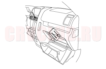
- After running the air conditioning for 10 minutes under the above test conditions, read the delivery temperature from the thermometer in the center vent, the intake temperature near the blower unit behind the glove box and the high and low system pressure from the A/C gauges.
21-59
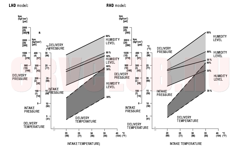
- To complete the charts:
- Mark the delivery temperature along the vertical line.
- Mark the intake temperature (ambient air temperature) along the bottom line.
- Draw a line straight up from the air temperature to the humidity.
- Mark a point 10 % above and 10 % below the humidity level.
- From each point, draw a horizontal line across the delivery temperature.
- The delivery temperature should fall between the two lines.
- Complete the low-side pressure test and high-side pressure test in the same way.
- Any measurements outside the line may indicate the need for further inspection.
|
HVAC 21-1
Air Conditioning21-31 |