21-60Climate Control21-61
|
HVAC 21-1
21-60Climate Control21-61 |
21-60Climate Control21-61
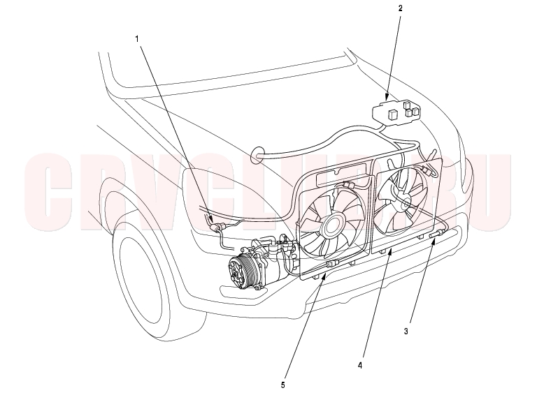
Component Location Index
NOTE: LHD type is shown, RHD type is similar.
Replacement, page 21-51 Replacement, page 21-46 ; Clutch Check, page 21-47 ; Clutch Overhaul, page 21-48 ; Thermal Protector Check, page 21-47 ; Thermal Protector Replacement, page 21-50 ; Relief Valve Replacement, page 21-50
Component Location Index (cont'd)21-62
NOTE: LHD type is shown, RHD type is similar.
BLOWER MOTOR RELAY, RADIATOR FAN RELAY, CONDENSER FAN RELAY, COMPRESSOR CLUTCH RELAY
Test, page 22A-60 Replacement, page 21-89 ; Test, page 21-89
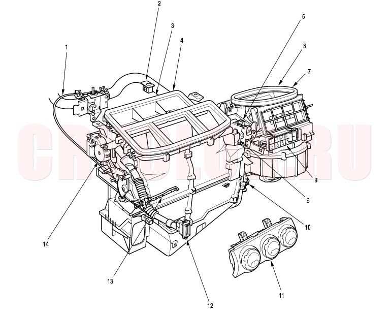
21-63
NOTE: LHD type is shown, RHD type is symmetrical.
Adjustment, page 21-30 Replacement, page 21-90 ; Test, page 21-90 Replacement, page 21-28 Replacement, page 21-45 Test, page 21-23 ; Replacement, page 21-23 Removal and Installation, page 21-26 Replacement, page 21-27 Replacement, page 21-25 Test, page 21-22 ; Replacement, page 21-22 Test, page 21-24 Removal and Installation, page 21-91 Replacement, page 21-88 ; Test, page 21-88 Replacement, page 21-44 ; Test, page 21-44 Test, page 21-21 ; Replacement, page 21-21
General Troubleshooting Information21-64
How to Retrieve a DTC
The Climate Control Unit has a self-diagnosis function.
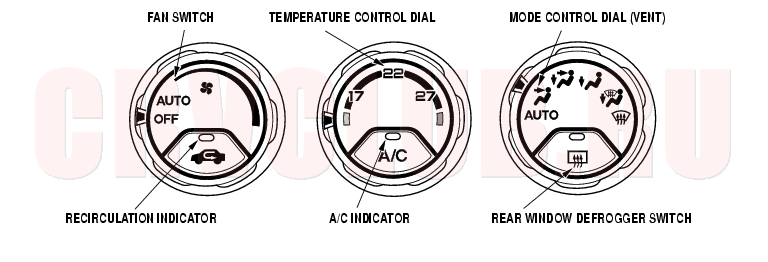
Running the Self-diagnosis Function
- Turn the ignition switch OFF.
- Turn the fan switch OFF, the temperature control dial on Max Cool and the mode control dial on Vent.
- Turn the ignition switch ON (II), then press and hold the recirculation control switch. Within 10 seconds while holding the switch down, press the rear window defogger switch five times. The recirculation indicator blinks two times, then the self-diagnosis will begin. If there is any problem in the system after self-diagnosis is finished, the recirculation indicator will blink the Diagnostic Trouble Code (DTC) 1 through 13, When problems in the evaporator temperature sensor circuit are detected (codes 14 and 15), the A/C indicator will blink the DTC. If no DTC's are found, the indicator will not blink.
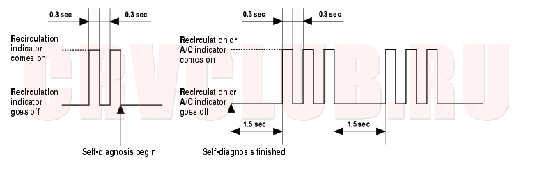
Example of DTC indication Pattern (DTC 3)
Resetting the Self-diagnosis Function
Turn the ignition switch OFF to cancel the self-diagnosis function. After completing repair work, run the self-diagnosis function again to make sure that there are no other malfunctions.
DTC Troubleshooting Index21-65
1 An open in the in-car temperature sensor circuit (see page 21-69) 2 A short in the in-car temperature sensor circuit (see page 21-70) 3 An open in the outside air temperature sensor circuit (see page 21-70) 4 A short in the outside air temperature sensor circuit (see page 21-72) 5 An open in the sunlight sensor circuit (see page 21-72) 6 A short in the sunlight sensor circuit (see page 21-73) 7 An open in the air mix control motor circuit (see page 21-74) 8 A short in the air mix control motor circuit (see page 21-74) 9 A problem in the air mix control linkage, door, or motor (see page 21-75) 10 An open or short in the mode control motor circuit (see page 21-76) 11 A problem in the mode control linkage, doors, or motor (see page 21-77) 12 A problem in the blower motor circuit (see page 21-78) 13 A problem in the EEPROM in the climate control unit; the control unit must be replaced (see page 21-91)
14 An open in the evaporator temperature sensor circuit (see page 21-81) 15 A short in the evaporator temperature sensor circuit (see page 21-82)
In case of multiple problems, the recirculation or A/C indicator will indicate only the DTC with the least number of blinks.
Symptom Troubleshooting Index21-66
Recirculation control doors do not change between Fresh and Recirculate Recirculation Control Motor Circuit Troubleshooting (see page 21-83) Blown fuse No. 14 (10A) in the under-dash fuse/relay box Cleanliness and tightness of all connectors The blower motor does not run immediately even through the engine is fully warmed up NOTE: The temperature control dial must be set between 18°C (64°F) and 32°C (90°F) ECT Sensor Circuit Troubleshooting
(see page 21-87)Cleanliness and tightness of all connectors Both heater and A/C do not work Climate Control Power and Ground Circuits Troubleshooting (see page 21-85) Blown fuse No. 14 (10A) in the under-dash fuse/relay box Poor ground at G501 Cleanliness and tightness of all connectors Condenser fan does not run at all (but radiator fan runs with the A/C on) Condenser Fan Circuit Troubleshooting
(see page 21-38)Blown fuse No. 1 (20A) in the under-hood fuse/relay box, and No. 14 (10A) in the under-dash fuse/relay box Poor ground at G201 Cleanliness and tightness of all connectors Both fans do not run with the A/C on Radiator and Condenser Fans Common Circuit Troubleshooting (see page 21-39) Blown fuse No. 1 (20A) and No. 4 (20A) in the under-hood fuse/relay box, and No. 14 (10A) in the under-dash fuse/relay box Poor ground at G201 Cleanliness and tightness of all connectors Compressor clutch does not engage Compressor Clutch Circuit Troubleshooting (see page 21-40) Blown fuse No. 1 (20A) in the under-hood fuse/relay box, and No. 14 (10A) in the under-dash fuse/relay box Cleanliness and tightness of all connectors A/C System does not come on (both fans and compressor) A/C Pressure Switch Circuit Troubleshooting (see page 21-86) Cleanliness and tightness of all connectors
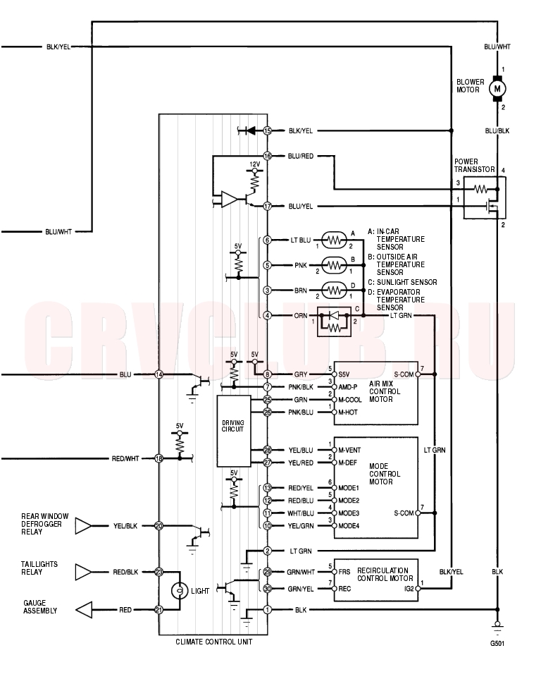
System Description21-67
Climate Control Unit Inputs and Outputs
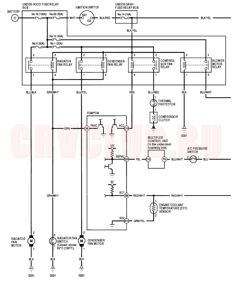
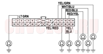
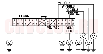
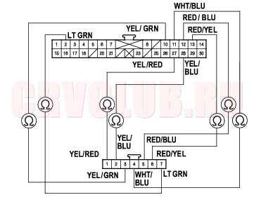
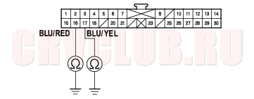
Circuit Diagram21-68
21-69
DTC Troubleshooting21-70
DTC 1: An Open in the In-car Temperature Sensor Circuit
- Remove the in-car temperature sensor (see page 21-88) .
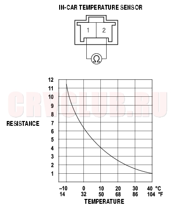
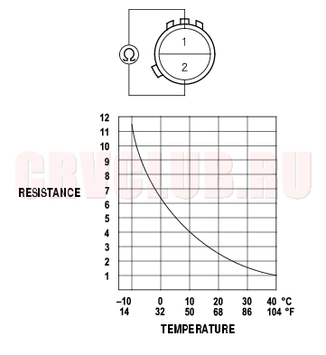
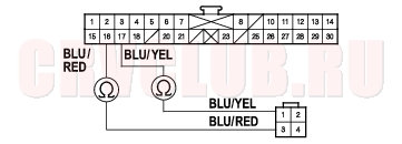
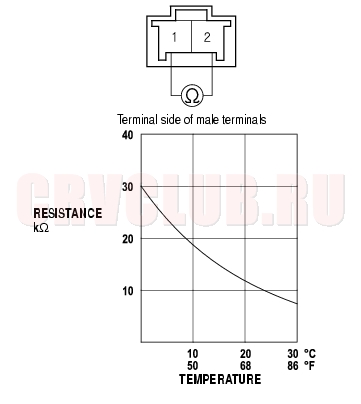
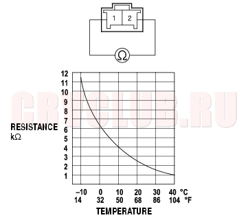
- Measure the resistance between the No. 1 and No. 2 terminals of the in-car temperature sensor.
*Check for change in resistance by heating or cooling the sensor with a hair drier.
Is the resistance within the specifications shown on the graph?
Yes : Go to step 3.
No : Replace the in-car temperature sensor.

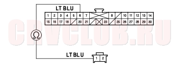
- Disconnect the climate control unit 30P connector.
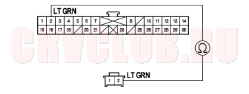
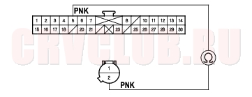
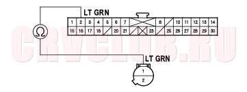
- Check for continuity between the No. 6 terminal of the climate control unit 30P connector and the No. 1 terminal of the in-car temperature sensor 2P connector.
Is there continuity?
Yes : Go to step 5.
No : Repair open in the wire between the climate control unit and the in-car temperature sensor.
- Check for continuity between the No. 2 terminal of the climate control unit 30P connector and the No. 2 terminal of the in-car temperature sensor 2P connector.
Is there continuity?
Yes : Check for loose wires or poor connections at the climate control unit 30P connector and at the in-car temperature sensor 2P connector. If the connections are good, substitute a known-good climate control unit, and recheck. If the symptom/indication goes away, replace the original climate control unit.
No : Repair open in the wire between the climate control unit and the in-car temperature sensor.
21-71
DTC 2: A Short in the In-car Temperature Sensor Circuit
- Remove the in-car temperature sensor (see page 21-88) .
- Test the in-car temperature sensor (see page 21-88) .
Is the resistance within the specifications shown on the graph?
Yes : Go to step 3.
No : Replace the in-car temperature sensor.
- Disconnect the climate control unit 30P connector.
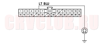
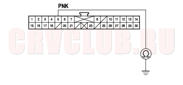
- Check for continuity between the No. 6 terminal of the climate control unit 30P connector and body ground.
Is there continuity?
Yes : Repair short to body ground in the wire between the climate control unit and the in-car temperature sensor.
No : Substitute a known-good climate control unit, and recheck. If the symptom/indication goes away, replace the original climate control unit.
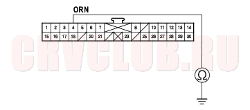
DTC 3: An Open in the Outside Air Temperature Sensor Circuit
- Remove the outside air temperature sensor (see page 21-89) .
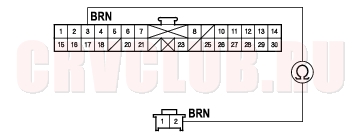
- Measure the resistance between the No. 1 and No. 2 terminals of the outside air temperature sensor.
*Dip the sensor in ice water, and measure resistance. Then pour hot water on the sensor, and check for change in resistance.
Is the resistance within the specifications shown on the graph?
Yes : Go to step 3.
No : Replace the outside air temperature sensor.
DTC Troubleshooting (cont'd)21-72
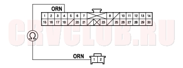
- Check for continuity between the No. 5 terminal of the climate control unit 30P connector and the No. 2 terminal of the outside air temperature sensor 2P connector.
Is there continuity?
Yes : Go to step 5.
No : Repair open in the wire between the climate control unit and the outside air temperature sensor.
- Check for continuity between the No. 2 terminal of the climate control unit 30P connector and the No. 1 terminal of the outside air temperature sensor 2P connector.
Is there continuity?
Yes : Check for loose wires or poor connections at the climate control unit 30P connector and at the outside air temperature sensor 2P connector. If the connections are good, substitute a known-good climate control unit, and recheck. If the symptom/indication goes away, replace the original climate control unit.
No : Repair open in the wire between the climate control unit and the outside air temperature sensor.
21-73
DTC 4: A Short in the Outside Air Temperature Sensor Circuit
- Remove the outside air temperature sensor (see page 21-89) .
- Test the outside air temperature sensor (see page 21-89) .
Is the resistance within the specifications shown on the graph?
Yes : Go to step 3.
No : Replace the outside air temperature sensor.
- Disconnect the climate control unit 30P connector.
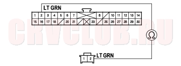
- Check for continuity between the No. 5 terminal of the climate control unit 30P connector and body ground.
Is there continuity?
Yes : Repair short to body ground in the wire between the climate control unit and the outside air temperature sensor.
No : Substitute a known-good climate control unit, and recheck. If the symptom/indication goes away, replace the original climate control unit.
DTC 5: An Open in the Sunlight Sensor Circuit
- Disconnect the sunlight sensor 2P connector.
- Disconnect the climate control unit 30P connector.
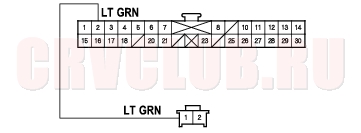
- Check for continuity between the No. 4 terminal of the climate control unit 30P connector and the No. 1 terminal of the sunlight sensor 2P connector.
Is there continuity?
Yes : Go to step 4.
No : Repair open in the wire between the climate control unit and the sunlight sensor.
DTC Troubleshooting (cont'd)21-74
- Check for continuity between the No. 2 terminal of the climate control unit 30P connector and the No. 2 terminal of the sunlight sensor 2P connector.
Is there continuity?
Yes : Go to step 5.
No : Repair open in the wire between the climate control unit and the sunlight sensor.
- Reconnect the sunlight sensor 2P connector.
- Reconnect the climate control unit 30P connector.
- Test the sunlight sensor (see page 21-90) .
Is the sunlight sensor OK?
Yes : Check for loose wires or poor connections at the climate control unit 30P connector and at the sunlight sensor 2P connector. If the connections are good, substitute a known-good climate control unit, and recheck. If the symptom/indication goes away, replace the original climate control unit.
No : Replace the sunlight sensor.
DTC 6: A Short in the Sunlight Sensor Circuit
- Disconnect the sunlight sensor 2P connector.
- Disconnect the climate control unit 30P connector.
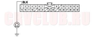
- Check for continuity between the No. 4 terminal of the climate control unit 30P connector and body ground.
Is there continuity?
Yes : Repair short to body ground in the wire between the climate control unit and the sunlight sensor.
No : Go to step 4.
- Reconnect the sunlight sensor 2P connector.
- Reconnect the climate control unit 30P connector.
- Test the sunlight sensor (see page 21-90) .
Is the sunlight sensor OK?
Yes : Substitute a known-good climate control unit, and recheck. If the symptom/indication goes away, replace the original climate control unit.
No : Replace the sunlight sensor.
21-75
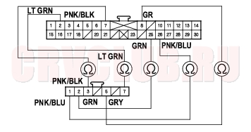
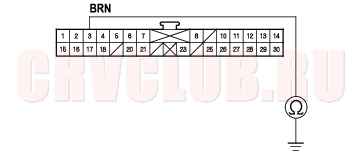
DTC 7: An Open in the Air Mix Control Motor Circuit
- Disconnect the air mix control motor 7P connector.
- Disconnect the climate control unit 30P connector.
- Check for continuity between following terminals of the climate control unit 30P connector and the air mix control motor 7P connector.
Is there continuity?
Yes : Check for loose wires or poor connections at the climate control unit 30P connector and at the air mix control motor 7P connector. If the connections are good, substitute a known-good climate control unit, and recheck. If the symptom/indication goes away, replace the original climate control unit.
No : Repair any open in he wire(s) between the climate control unit and the air mix control motor.
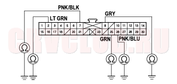
DTC 8: A Short in the Air Mix Control Motor Circuit
- Disconnect the air mix control motor 7P connector.
- Disconnect the climate control unit 30P connector.
- Check for continuity between body ground and the climate control unit 30P connector terminals No. 2, 7, 8, 25 and 26 individually.
Is there continuity?
Yes : Repair any short to body ground in the wire(s) between the climate control unit and the air mix control motor.
No : Go to step 4.
DTC Troubleshooting (cont'd)21-76
Is there any voltage?
Yes : Repair any short to power in the wire(s) between the climate control unit and the air mix control motor. This short also may damage the climate control unit. Repair the short to power before replacing the climate control unit.
No : Substitute a known-good climate control unit, and recheck. If the symptom/indication goes away, replace the original climate control unit.
DTC 9: A Problem in the Air Mix Control Linkage, Door, or Motor
- Test the air mix control motor (see page 21-21) .
Is the air mix control motor OK?
Yes : Substitute a known-good climate control unit, and recheck. If the symptom/indication goes away, replace the original climate control unit.
No : Go to step 2.
- Remove the air mix control motor (see page 21-21) .
- Check the air mix control linkage and door for smooth movement.
Do the air mix control linkage and door move smoothly?
Yes : Replace the air mix control motor.
No : Repair the air mix control linkage or door.
21-77
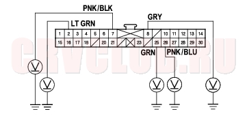
DTC 10: An Open or Short in the Mode Control Motor Circuit
- Disconnect the mode control motor 7P connector.
- Disconnect the climate control unit 30P connector.
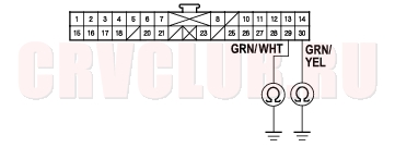
- Check for continuity between body ground and the climate control unit 30P connector terminals No. 2, 10, 11, 12, 13, 27 and 28 individually.
Is there continuity?
Yes : Repair any short to body ground in the wire(s) between the climate control unit and the mode control motor.
No : Go to step 4.
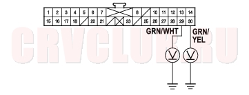
Is there any voltage?
Yes : Repair any short to power in the wire(s) between the climate control unit and the mode control motor. This short also may damage the climate control unit. Repair the short to power before replacing the climate control unit.
No : Go to step 5.
DTC Troubleshooting (cont'd)21-78
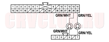
- Turn the ignition switch OFF,and check for continuity between following terminals of the climate control unit 30P connector and the mode control motor 7P connector.
Is there continuity?
Yes : Check for loose wires or poor connections at the climate control unit 30P connector and at the mode control motor 7P connector. If the connections are good, substitute a known-good climate control unit, and recheck. If the symptom/indication goes away, replace the original climate control unit.
No : Repair any open in the wire(s) between the climate control unit and the mode control motor.
DTC 11: A Problem in the Mode Control Linkage, Doors, or Motor
- Test the mode control motor (see page 21-22) .
Is the mode control motor OK?
Yes : Substitute a known-good climate control unit, and recheck. If the symptom/indication goes away, replace the original climate control unit.
No : Go to step 2.
- Remove the mode control motor (see page 21-22) .
- Check the mode control linkage and doors for smooth movement.
Do the mode control linkage and doors move smoothly?
Yes : Replace the mode control motor.
No : Repair the mode control linkage or doors.
21-79
DTC 12: A Problem in the Blower Motor Circuit
- Check the No. 12 (40A) fuse in the under-hood fuse/relay box, and the No. 14 (10A) fuse in the under-dash fuse/relay box.
Are the fuses OK?
Yes : Go to step 2.
No : Replace the fuse(s), and recheck.
Does the blower motor run?
Yes : Go to step 4.
No : Go to step 17.
- Turn the ignition switch OFF.
- Disconnect the jumper wire.
- Disconnect the power transistor 4P connector.
- Check for continuity between the No. 2 terminal of the power transistor 4P connector and body ground.
Is there continuity?
Yes : Go to step 8.
No : Check for an open in the wire between the power transistor and body ground. If the wire is OK, check for poor ground at G501.
Does the blower motor run at high speed?
Yes : Go to step 10.
No : Repair open in the wire between the power transistor and the blower motor.
DTC Troubleshooting (cont'd)21-80
- Disconnect the climate control unit 30P connector.
- Check for continuity between the No. 16 and No. 17 terminals of the climate control unit 30P connector and body ground individually.
Is there continuity?
Yes : Repair any short to body ground in the wire(s) between the climate control unit and the power transistor.
No : Go to step 14.
- Check for continuity between the following terminals of the climate control unit 30P connector and power transistor 4P connector.
30P: 4P: No. 17 No. 1 No. 16 No. 3
Is there continuity?
Yes : Go to step 15.
No : Repair any open in the wire(s) between the climate control unit and the power transistor.
- Reconnect the climate control unit 30P connector.
- Test the power transistor (see page 21-24) .
Is the power transistor OK?
Yes : Check for loose wires or poor connections at the climate control unit 30P connector and at the power transistor 4P connector. If the connections are good, substitute a known-good climate control unit, and recheck. If the symptom/indication goes away, replace the original climate control unit.
No : Replace the power transistor.
- Disconnect the jumper wire.
- Disconnect the blower motor 2P connector.
- Measure the voltage between the No. 1 terminal of the blower motor 2P connector and body ground.
Is there battery voltage?
Yes : Replace the blower motor.
No : Go to step 20.
- Turn the ignition switch OFF.
- Remove the blower motor relay from the under-hood fuse/relay box, and test it (see page 22A-60) .
Is there relay OK?
Yes : Go to step 22.
No : Replace the blower motor relay.
21-81
Is there battery voltage?
Yes : Go to step 23.
No : Replace the under-hood fuse/relay box.
- Turn the ignition switch ON (II).
- Measure the voltage between the No. 2 terminal of the blower motor relay 4P socket and body ground.
Is there battery voltage?
Yes : Go to step 25.
No : Repair open in the wire between the No. 14 fuse in the under-dash fuse/relay box and the blower motor relay.
- Turn the ignition switch OFF.
- Check for continuity between the No. 1 terminal of the blower motor relay 4P socket and body ground.
Is there contnuity?
Yes : Repair open in the wire between the blower motor relay and the blower motor.
No : Check for an open in the wire between the blower motor relay and body ground. If the wire is OK, check for poor ground at G201.
DTC Troubleshooting (cont'd)21-82
DTC 14: An Open in the Evaporator Temperature Sensor Circuit
- Remove the evaporator temperature sensor (see page 21-44) .
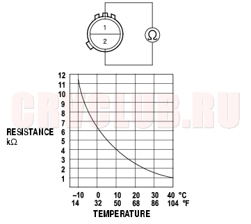
- Measure the resistance between the No. 1 and No. 2 terminals of the evaporator temperature sensor.
- *Dip the sensor in ice water, and measure resistance. Then pour hot water on the sensor, and check for change in resistance.
Is the resistance within the specifications shown on the graph?
Yes : Go to step 3.
No : Replace the evaporator temperature sensor.
- Disconnect the climate control unit 30P connector.
- Check for continuity between the No. 3 terminal of the climate control unit 30P connector and the No. 2 terminal of the evaporator temperature sensor 2P connector.
Is there continuity?
Yes : Go to step 5.
No : Repair open in the wire between the climate control unit and the evaporator temperature sensor.
21-83
- Check for continuity between the No. 2 terminal of the climate control unit 30P connector and the No. 1 terminal of the evaporator temperature sensor 2P connector.
Is there continuity?
Yes : Check for loose wires or poor connections at the climate control unit 30P connector and at the evaporator temperature sensor 2P connector. If the connections are good, substitute a known-good climate control unit, and recheck. If the symptom/indication goes away, replace the original climate control unit.
No : Repair open in the wire between the climate control unit and the evaporator temperature sensor.
DTC 15: A Short in the Evaporator Temperature Sensor Circuit
- Remove the evaporator temperature sensor
(see page 21-44) .
- Test the evaporator temperature sensor
(see page 21-44) .
Is the resistance within the specifications shown on the graph?
Yes : Go to step 3.
No : Replace the evaporator temperature sensor.
- Disconnect the climate control unit 30P connector.
- Check for continuity between the No. 3 terminal of the climate control unit 30P connector and body ground.
Is there continuity?
Yes : Repair short to body ground in the wire between the climate control unit and the evaporator temperature sensor.
No : Substitute a known-good climate control unit, and recheck. If the symptom/indication goes away, replace the original climate control unit.
Recirculation Control Motor Circuit Troubleshooting21-84
Is the fuse OK?
Yes : Go to step 2.
No : Replace the fuse, and recheck.
- Disconnect the recirculation control motor 7P connector.
- Turn the ignition switch ON (II).
- Measure the voltage between the No. 1 terminal of the recirculation control motor 7P connector and body ground.
Is there battery voltage?
Yes : Go to step 5.
No : Repair open in the wire between the No. 14 fuse in the under-dash fuse/relay box and the recirculation control motor .
- Turn the ignition switch OFF.
- Test the recirculation control motor (see page 21-23) .
Is the recirculation control motor OK?
Yes : Go to step 7.
No : Go to step 12.
- Disconnect the climate control unit 30P connector.
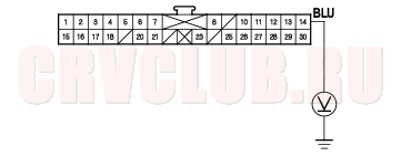
- Check for continuity between the No. 29 and No. 30 terminals of the climate control unit 30P connector and body ground individually.
Is there continuity?
Yes : Repair any short to body ground in the wire(s) between the climate control unit and the recirculation control motor.
No : Go to step 9.
Is there any voltage?
Yes : Repair any short to power in the wire(s) between the climate control unit and the recirculation control motor. This short also may damage the climate control unit. Repair the short to power before replacing the climate control unit.
No : Go to step 10.
21-85
- Turn the ignition switch OFF.
- Check for continuity between the following terminals of the climate control unit 30P connector and the recirculation control motor 7P connector.
30P: 7P: No. 29 No. 5 No. 30 No. 7
Is there continuity?
Yes : Check for loose wires or poor connections at the climate control unit 30P connector and at recirculation control motor 7P connector. If the connections are good, substitute a known-good climate control unit, and recheck. If the symptom/indication goes away, replace the original climate control unit.
No : Repair any open in the wire(s) between the climate control unit and the recirculation control motor.
- Remove the recirculation contol motor (see page 21-23) .
- Check the recirculation control linkage and doors for smooth movement.
Do the recirculation control linkage and doors move smoothly?
Yes : Replace the recirculation control motor.
No : Repair the recirculation control linkage or doors.
Climate Control Power and Ground Circuits Troubleshooting21-86
Is the fuse OK?
Yes : Go to step 2.
No : Replace the fuse, and recheck.
- Disconnect the climate control unit 30P connector.
- Turn the ignition switch ON (II).
- Measure the voltage between the No. 15 terminal of the climate control unit 30P connector and body ground.
Is there battery voltage?
Yes : Go to step 5.
No : Repair open in the wire between the No. 14 fuse in the under-dash fuse/relay box and the climate control unit.
- Turn the ignition switch OFF.
- Check for continuity between the No. 1 terminal of the climate control unit 30P connector and body ground.
Is there continuity?
Yes : Check for loose wires or poor connections at the climate control unit 30P connector. If the connections are good,substitute a known-good climate control unit, and recheck. If the symptom/indication goes away, replace the original climate control unit.
No : Check for an open in the wire between the climate control unit and body ground. If the wire is OK, check for poor ground at G501.
A/C Pressure Switch Circuit Troubleshooting21-87
Does the blower motor run on all speeds?
Yes : Go to step 3.
No : Troubleshoot the blower motor circuit
(see page 21-78).
- Disconnect the A/C pressure switch 2P connector.
- Turn the ignition switch ON (II).
- Measure the voltage between the No. 2 terminal of the A/C pressure switch 2P connector and body ground.
Is there battery voltage?
Yes : Go to step 6.
No : Go to step 12.
- Turn the ignition switch OFF.
- Check for continuity between the No. 1 and No. 2 terminals of the A/C pressure switch.
Is there continuity?
Yes : Go to step 8.
No : Go to step 14.
- Reconnect the A/C pressure switch 2P connector.
- Disconnect the climate control unit 30P connector.
- Turn the ignition switch ON (II).
- Measure the voltage between the No. 14 terminal of the climate control unit 30P connector and body ground.
Is battery voltage?
Yes : Check for loose wires or poor connections at the climate control unit 30P connector and at the A/C pressure switch 2P connector. If the connections are good, substitute a known-good climate control unit, and recheck. If the symptom/indication goes away, replace the original climate control unit.
No : Repair open in the wire between the climate control unit and the A/C pressure switch.
A/C Pressure Switch Circuit Troubleshooting (cont'd)21-88
- Make sure the A/C switch is OFF.
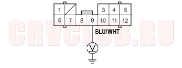
- Measure the voltage between the No. 9 terminal of under-dash fuse/relay box connector F (12P) and body ground with the under-dash fuse/relay box connectors connected.
Is there 5V or more?
Yes : Repair open in the wire between the under-dash fuse/relay box and the A/C pressure switch.
No : Refer to the multiplex control system (see page 22A-227).
NOTE: Check for multiplex codes in mode 1. Follow the troubleshooting for any codes found. If no codes are found, subsititute a known-good multiplex control unit and a PCM one at a time. Is the pressure within specifications?
Yes : Replace the A/C pressure switch.
No : Repair the A/C pressure problem.
ECT Sensor Circuit Troubleshooting21-88
Does the malfunction indicator lamp come on?
Yes : Refer to the fuel and emissions section (see page 11-3).
No : Go to step 2.
- Turn the ignition switch OFF.
- Disconnect the ECT sensor 2P connector.
- Disconnect the climate control unit 30P connector.
- Turn the ignition switch ON (II).
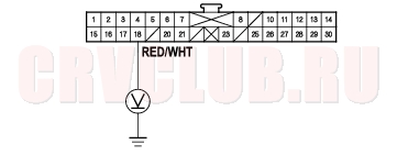
- Measure the voltage between the No. 18 terminal of the climate control unit 30P connector and body ground.
Is there about 5 V?
Yes : Check for loose wires or poor connections at the climate control unit 30P connector and at the ECT sensor 2P connector. If the connections are good, substitute a known-good climate control unit, and recheck. If the symptom/indication goes away, replace the original climate control unit.
No : Repair open in the wire between the climate control unit and the ECT sensor.
In-car Temperature Sensor Replacement21-89
NOTE: LHD type is shown, RHD type is symmetrical.
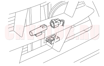
- Remove the driver's dashboard lower cover (see page 20-88) .
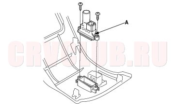
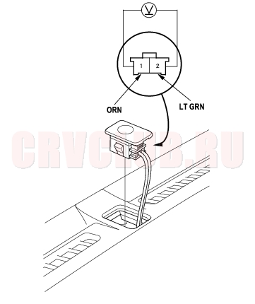
- Disconnect the 2P connector and the air hose, then remove the self-tapping screws and the in-car temperature sensor (A) from the dashboard.
- Install the sensor in the reverse order of removal. Be sure to connect the air hose securely.
In-car Temperature Sensor Test21-89
Check for a change in resistance by heating or cooling the sensor with a hair drier.
Compare the resistance reading between the No. 1 and No. 2 terminals of the in-car temperature sensor with the specifications shown in the graph; the resistance should be within the specifications.
Outside Air Temperature Sensor Replacement21-90
- Release the lock, and remove the outside air temperature sensor, then disconnect the 2P connector.
- Install the sensor in the reverse order of removal.
Outside Air Temperature Sensor Test21-90
Dip the sensor in ice water, and measure the resistance. Then pour hot water on the sensor, and check for a change in resistance.
Compare the resistance reading between the No. 1 and No. 2 terminals of the outside air temperature sensor with the specifications shown in the graph; the resistance should be within the specifications.
Sunlight Sensor Replacement21-91
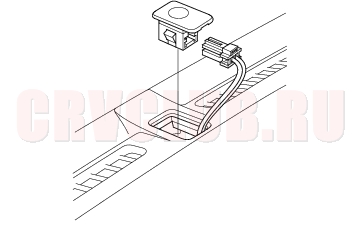
- Remove the sunlight sensor from the dashboard, then disconnect the 2P connector. Be careful not to damage the sensor and the dashboard.
- Install the sensor in the reverse order of removal.
Sunlight Sensor Test21-91
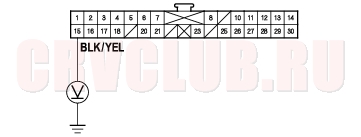
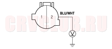
Turn the ignition switch ON (II). Measure the voltage between the terminals with the (+) probe on the No. 1 terminal and the (-) probe on the No. 2 terminal with the 2P connector connected. The voltage will not change under the light at a flashlight or fluorescent lamp. Voltage should be:
3.6 - 3.7 V or more with the sensor out of direct. 3.6 - 3.5 V or less with the sensor is direct sunlight.
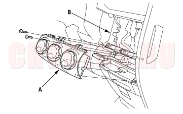
Climate Control Unit Removal and Installation21-92
- Remove the cool box (see page 20-90) .
- Remove the self-tapping screws and the heater control panel (A) from the dashboard (B).
- Install the control panel in the reverse order of removal. After installation, operate the control panel controls to see whether it works properly.
- Run the self-diagnosis function to confirm that there are no problems in the system (see page 21-63) .
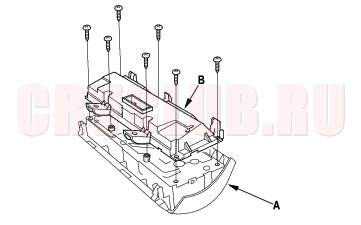
Climate Control Unit Bulb Replacement21-92
- Discharge the static electricity (which accumulated on you when you removed the climate control unit) by touching the door striker or other body parts.
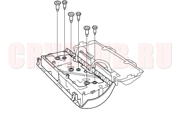
- Remove the self-tapping screws, then carefully separate the climate control unit display (A) from the control unit (B). Do not kink or pull on the wires between the display and control unit. Do not touch the electronic components on the printed circuit board in the control unit.
- Remove the bulb(s) with a flat-tip screw driver.
- Install the bulb(s) in the reverse order of removal.
|
HVAC 21-1
21-60Climate Control21-61 |