Heating21-2
|
HVAC 21-1
Heating21-2 |
Heating21-2
Special Tools
07NAB-HAC0100 A/C Clutch Holder
SUPPLEMENAL RESTRAINT SYSTEM (SRS) (If HVAC maintenance is required)
The CR-V SRS includes a driver's airbag in the steering wheel hub, a passenger's airbag in the dashboard above the glove box, seat belt tensioners in the front seat belt retractors, seat belt buckle tensioners in the front seat belt buckles, and side airbags in the front seat-backs. Information necessary to safely service the SRS is included in this Service Manual. Items marked with an asterisk (*) on the contents include or are located near SRS components. Servicing, disassembling, or replacing these items will require special precautions and tools, and should be done only by an authorized Honda dealer.
To avoid rendering the SRS inoperative, which could lead to personal injury or death in the event of a severe frontal collision, all SRS service work must be performed by an authorized Honda dealer. Improper service procedures, including incorrect removal and installation of the SRS could lead to personal injury caused by unintentional deployment of the airbags and side airbags. Do not bump the SRS unit. Otherwise, the system may fail in a collision, or the airbags may deploy when the ignition switch is ON (II). SRS electrical connectors are identified by yellow color coding. Related components are located in the steering column, front console, dashboard, dashboard lower panel, in the dashboard above the glove box, in the front seats, and around the floor. Do not use electrical test equipment on these circuits. Component Location Index21-3
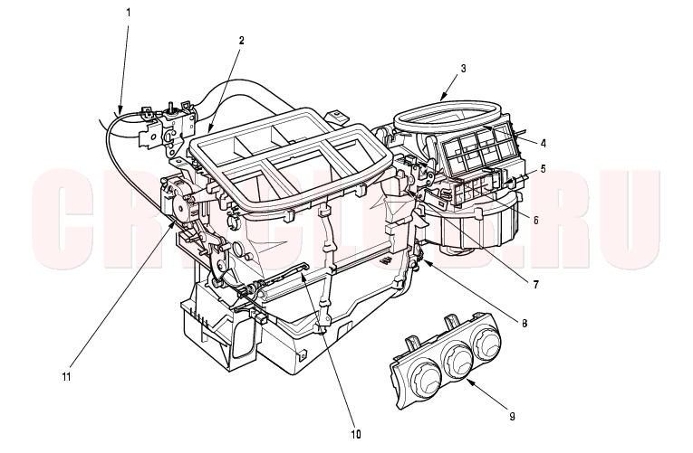
NOTE: LHD type is shown, RHD type is symmetrical.
Adjustment, page 21-30 Replacement, page 21-28 Removal and Installation, page 21-26 Replacement, page 21-27 Replacement, page 21-25 Test, page 21-23 ; Replacement, page 21-23 Test, page 21-22 ; Replacement, page 21-22 Test, page 21-24 Removal and Installation, page 21-24 Replacement, page 21-44 ; Test, page 21-44 Replacement, page 21-21 ; Test, page 21-21
General Troubleshooting Information21-4
How to Retrieve a DTC
The Heater Control Panel has a self-diagnosis function.
Running the Self-diagnosis Function
- Turn the ignition switch OFF.
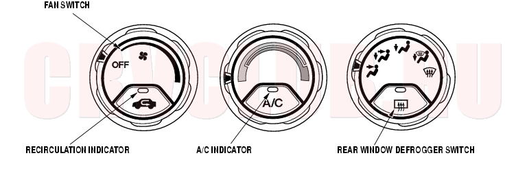
- Turn the fan switch OFF, the temperature control dial on Max Cool and the mode control dial on Vent.
- Turn the ignition switch ON (II), then press and hold the recirculation control switch. Within 10 seconds while holding the switch down, press the rear window defogger switch five times. The recirculation indicator blinks two times, then the self-diagnosis will begin. If there is any problem in the system after self-diagnosis is finished, the recirculation indicator will blink the Diagnostic Trouble Code (DTC) 7 through 13 when problems in the evaporator temperature sensor circuit are detected (codes 14 and 15), the A/C indicator will blink the DTC. If no DTC's are found, the indicator will not blink.
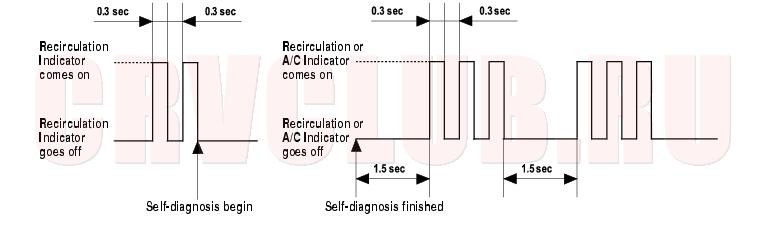
Example of DTC indication Pattern (DTC 3)
Resetting the Self-diagnosis Function
Turn the ignition switch OFF to cancel the self-diagnosis function. After completing repair work, run the self-diagnosis function again to make sure that there are no other malfunctions.
DTC Troubleshooting Index21-5
7 An open in the air mix control motor circuit (see page 21-9) 8 A short in the air mix control motor circuit (see page 21-9) 9 A problem in the air mix control linkage, door, or motor (see page 21-10) 10 An open or short in the mode control motor circuit (see page 21-11) 11 A problem in the mode control linkage, doors, or motor (see page 21-12) 12 A problem in the blower motor circuit (see page 21-13) 13 A problem in the EEPROM in the heater control panel; the control panel must be replaced (see page 21-24)
14
(With A/C)An open in the evaporator temperature sensor circuit (see page 21-16) 15
(With A/C)A short in the evaporator temperature sensor circuit (see page 21-17)
In case of multiple problems, the recirculation indicator will indicate only the DTC with the least number of blinks.
Symptom Troubleshooting Index21-6
Recirculation control doors do not change between Fresh and Recirculate Recirculation Control Motor Circuit Troubleshooting
(see page 21-18)Blown fuse No. 14 (10A) in the under-dash fuse/relay box Cleanliness and tightness of all connectors Both heater and A/C do not work Heater Control Power and Ground Circuits Troubleshooting (see page 21-20) Blown fuse No. 14 (10A) in the under-dash fuse/relay box Poor ground at G501 Cleanliness and tightness of all connectors
System Description21-7
Heater Control Panel Inputs and Outputs
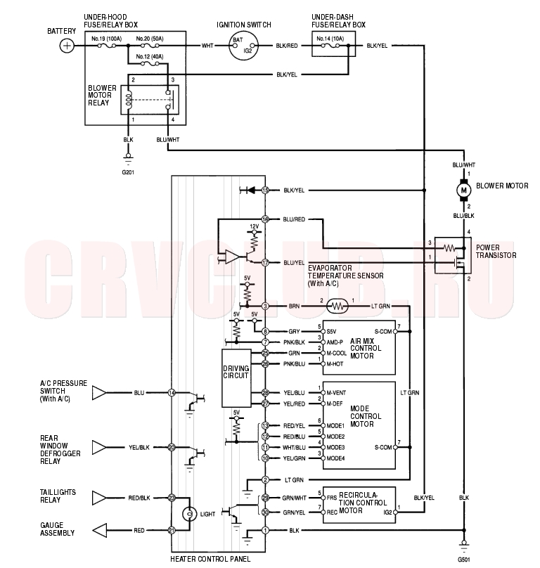
Circuit Diagram21-8
DTC Troubleshooting21-9
DTC 7: An Open in the Air Mix Control Motor Circuit
- Disconnect the air mix control motor 7P connector.
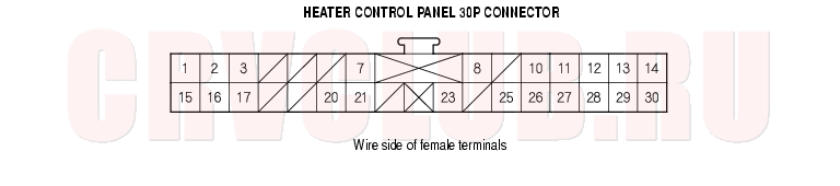
- Disconnect the heater control panel 30P connector.
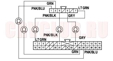
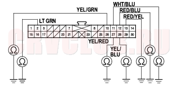
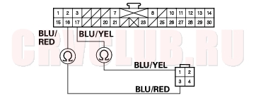
- Check for continuity between the following terminals of the heater control panel 30P connector and the air mix control motor 7P connector.
30P: 7P: No. 2 No. 7 No. 7 No. 3 No. 8 No. 5 No. 25 No. 2 No. 26 No. 1
Is there continuity?
Yes : Check for loose wires or poor connections at the heater control panel 30P connector and at the air mix control motor 7P connector. If the connections are good, substitute a known-good heater control panel, and recheck. If the symptom/indication goes away, replace the original heater control panel.

No : Repair any open in the wire(s) between the heater control panel and the air mix control motor.
DTC 8: A Short in the Air Mix Control Motor Circuit
- Disconnect the air mix control motor 7P connector.
- Disconnect the heater control panel 30P connector.
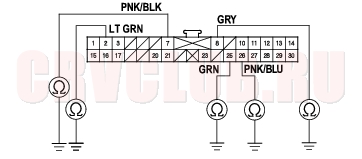
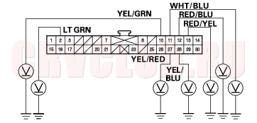
- Check for continuity between body ground and heater control panel 30P connector terminals No. 2, 7, 8, 25, and 26 individually.
Is there continuity?
Yes : Repair any short to body ground in the wire(s) between the heater control panel and the air mix control motor.
No : Go to step 4.
DTC Troubleshooting (cont'd)21-10
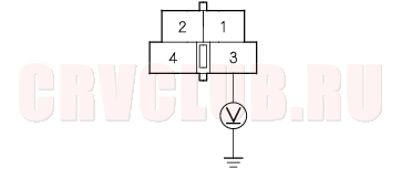
Is there any voltage?
Yes : Repair any short to power in the wire(s) between the heater control panel and the air mix control motor. This short also may damage the heater control panel. Repair the short to power before replacing the heater control panel.
No : Substitute a known-good heater control panel, and recheck. If the symptom/indication goes away, replace the original heater control panel.
DTC 9: A Problem in the Air Mix Control Linkage, Door, or Motor
- Test the air mix control motor (see page 21-21) .
Is the air mix control motor OK?
Yes : Substitute a known-good heater control panel, and recheck. If the symptom/indication goes away, replace the original heater control panel.
No : Go to step 2.
- Remove the air mix control motor (see page 21-21) .
- Check the air mix control linkage and door for smooth movement.
Do the air mix control linkage and door move smoothly?
Yes : Replace the air mix control motor.
No : Repair the air mix control linkage or door.
21-11
DTC 10: An Open or Short in the Mode Control Motor Circuit
- Disconnect the mode control motor 7P connector.
- Disconnect the heater control panel 30P connector.
- Check for continuity between body ground and the heater control panel 30P connector terminals No. 2, 10, 11, 12, 13, 27, and 28 individually.
Is there continuity?
Yes : Repair any short to body ground in the wire(s) between the heater control panel and the mode control motor.
No : Go to step 4.
Is there any voltage?
Yes : Repair any short to power in the wire(s) between the heater control panel and the mode control motor. This short also may damage the heater control panel. Repair the short to power before replacing the heater control panel.
No : Go to step 5.
DTC Troubleshooting (cont'd)21-12
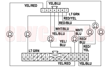
- Turn the ignition switch OFF, and check for continuity between the following terminals of the heater control panel 30P connector and the mode control motor 7P connector.
30P: 7P: No. 2 No. 7 No. 10 No. 3 No. 11 No. 4 No. 12 No. 5 No. 13 No. 6 No. 28 No. 2 No. 27 No. 1
Is there continuity?
Yes : Check for loose wires or poor connections at the heater control panel 30P connector and at the mode control motor 7P connector. If the connections are good, substitute a known-good heater control panel, and recheck. If the symptom/indication goes away, replace the original heater control panel.
No : Repair any open in the wire(s) between the heater control panel and the mode control motor.
DTC 11: A Problem in the Mode Control Linkage, Doors, or Motor
- Test the mode control motor (see page 21-22) .
Is the mode control motor OK?
Yes : Substitute a known-good heater control panel, and recheck. If the symptom/indication goes away, replace the original heater control panel.
No : Go to step 2.
- Remove the mode control motor (see page 21-22) .
- Check the mode control linkage and doors for smooth movement.
Do the mode control linkage and doors move smoothly?
Yes : Replace the mode control motor.
No : Repair the mode control linkage or doors.
21-13
DTC 12: A Problem in the Blower Motor Circuit
- Check the No. 12 (40A) fuse in the under-hood fuse/relay box, and the No. 14 (10A) fuse in the under-dash fuse/relay box.
Are the fuses OK?
Yes : Go to step 2.
No : Replace the fuse(s), and recheck.
Does the blower motor run?
Yes : Go to step 4.
No : Go to step 17.
- Turn the ignition switch OFF.
- Disconnect the jumper wire.
- Disconnect the power transistor 4P connector.
- Check for continuity between the No. 2 terminal of the power transistor 4P connector and body ground.
Is there continuity?
Yes : Go to step 8.
No : Check for an open in the wire between the power transistor and body ground. If the wire is OK, check for poor ground at G501.
Does the blower motor run at high speed?
Yes : Go to step 10.
No : Repair open in the wire between the power transistor and the blower motor.
DTC Troubleshooting (cont'd)21-14
- Disconnect the heater control panel 30P connector.
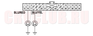
- Check for continuity between the No. 16 and No. 17 terminals of the heater control panel 30P connector and body ground individually.
Is there continuity?
Yes : Repair any short to body ground in the wire(s) between the heater control panel and the power transistor.
No : Go to step 14.
- Check for continuity between the following terminals of the heater control panel 30P connector and the power transistor 4P connector.
30P: 4P: No. 17 No. 1 No. 16 No. 3
Is there continuity?
Yes : Go to step 15.
No : Repair any open in the wire(s) between the heater control panel and the power transistor.
- Reconnect the heater control panel 30P connector.
- Test the power transistor (see page 21-24)
Is the power transistor OK?
Yes : Check for loose wires or poor connections at the heater control panel 30P connector and at the power transistor 4P connector. If the connections are good, substitute a known-good heater control panel, and recheck. If the symptom/indication goes away, replace the original heater control panel.
No : Replace the power transistor.
- Disconnect the jumper wire.
- Disconnect the blower motor 2P connector.
- Measure the voltage between the No. 1 terminal of the blower motor 2P connector and body ground.
Is there battery voltage?
Yes : Replace the blower motor.
No : Go to step 20.
- Turn the ignition switch OFF.
- Remove the blower motor relay from the under-hood fuse/relay box, and test it (see page 21-26) .
Is the relay OK?
Yes : Go to step 22.
No : Replace the blower motor relay.
21-15
Is there battery voltage?
Yes : Go to step 23.
No : Replace the under-hood fuse/relay box.
- Turn the ignition switch ON (II).
- Measure the voltage between the No. 2 terminal of the blower motor relay 4P socket and body ground.
Is there battery voltage?
Yes : Go to step 25.
No : Repair open in the wire between the No. 14 fuse in the under-dash fuse/relay box and the blower motor relay.
- Turn the ignition switch OFF.
- Check for continuity between the No. 1 terminal of the blower motor relay 4P socket and body ground.
Is there continuity?
Yes : Repair open in the wire between the blower motor relay and the blower motor.
No : Check for an open in the wire between the blower motor relay and body ground. If the wire is OK, check for poor ground at G501.
DTC Troubleshooting (cont'd)21-16
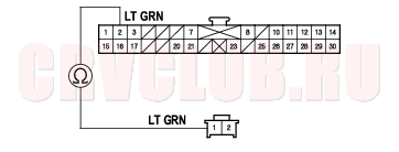
DTC 14: An Open in the Evaporator Temperature Sensor Circuit
- Remove the evaporator temperature sensor
(see page 21-44) .
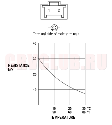
- Measure the resistance between the No. 1 and No. 2 terminals of the evaporator temperature sensor.
- *Dip the sensor in ice water, and measure resistance. Then pour hot water on the sensor, and check for change in resistance.
Is the resistance within the specifications shown on the graph?
Yes : Go to step 3.
No : Replace the evaporator temperature sensor.
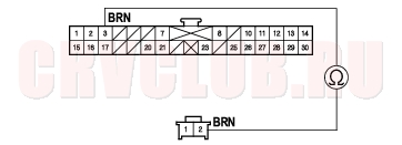
- Disconnect the heater control panel 30P connector.
- Check for continuity between the No. 3 terminal of the heater control panel 30P connector and the No. 2 terminal of the evaporator temperature sensor 2P connector.
Is there continuity?
Yes : Go to step 5.
No : Repair open in the wire between the heater control panel and the evaporator temperature sensor.
21-17
- Check for continuity between the No. 2 terminal of the heater control panel 30P connector and the No. 1 terminal of the evaporator temperature sensor 2P connector.
Is there continuity?
Yes : Check for loose wires or poor connections at the heater control panel 30P connector and at the evaporator temperature sensor 2P connector. If the connections are good, substitute a known-good heater control panel, and recheck. If the symptom/indication goes away, replace the original heater control panel.
No : Repair open in the wire between the heater control panel and the evaporator temperature sensor.
DTC 15: A Short in the Evaporator Temperature Sensor Circuit
- Remove the evaporator temperature sensor
(see page 21-44) .
- Test the evaporator temperature sensor
(see page 21-44) .
Is the resistance within the specifications shown on the graph?
Yes : Go to step 3.
No : Replace the evaporator temperature sensor.
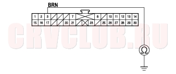
- Disconnect the heater control panel 30P connector.
- Check for continuity between the No. 3 terminal of the heater control panel 30P connector and body ground.
Is there continuity?
Yes : Repair short to body ground in the wire between the heater control panel and the evaporator temperature sensor.
No : Substitute a known-good heater control panel, and recheck. If the symptom/indication goes away, replace the original heater control panel.
Recirculation Control Motor Circuit Troubleshooting21-18
Is the fuse OK?
Yes : Go to step 2.
No : Replace the fuse, and recheck.
- Disconnect the recirculation control motor 7P connector.
- Turn the ignition switch ON (II).
- Measure the voltage between the No. 1 terminal of the recirculation control motor 7P connector and body ground.
Is there battery voltage?
Yes : Go to step 5.
No : Repair open in the wire between the No. 14 fuse in the under-dash fuse/relay box and the recirculation control motor.
- Turn the ignition switch OFF.
- Test the recirculation control motor (see page 21-23) .
Is the recirculation control motor OK?
Yes : Go to step 7.
No : Go to step 12.
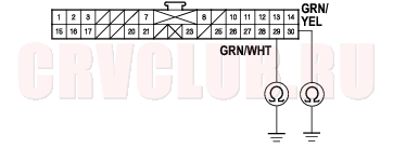
- Disconnect the heater control panel 30P connector.
- Check for continuity between the No. 29 and No. 30 terminals of the heater control panel 30P connector and body ground individually.
Is there continuity?
Yes : Repair any short to body ground in the wire(s) between the heater control panel and the recirculation control motor.
No : Go to step 9.
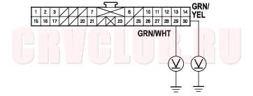
Is there any voltage?
Yes : Repair any short to power in the wire(s) between the heater control panel and the recirculation control motor. This short also may damage the heater control panel. Repair the short to power before replacing the heater control panel.
No : Go to step 10.
21-19
- Turn the ignition switch OFF.
- Check for continuity between the following terminals of the heater control panel 30P connector and the recirculation control motor 7P connector.
Is there continuity?
Yes : Check for loose wires or poor connections at the heater control panel 30P connector and at the recirculation control motor 7P connector. If the connections are good, substitute a known-good heater control panel, and recheck. If the symptom/indication goes away, replace the original heater control panel.
No : Repair any open in the wire(s) between the heater control panel and the recirculation control motor.
- Remove the recirculation contol motor (see page 21-23) .
- Check the recirculation control linkage and doors for smooth movement.
Do the recirculation control linkage and doors move smoothly?
Yes : Replace the recirculation control motor.
No : Repair the recirculation control linkage or doors.
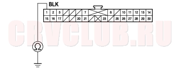
Heater Control Power and Ground Circuits Troubleshooting21-20
Is the fuse OK?
Yes : Go to step 2.
No : Replace the fuse, and recheck.
- Disconnect the heater control panel 30P connector.
- Turn the ignition switch ON (II).
- Measure the voltage between the No. 15 terminal of the heater control panel 30P connector and body ground.
Is there battery voltage?
Yes : Go to step 5.
No : Repair open in the wire between the No. 14 fuse in the under-dash fuse/relay box and the heater control panel.
- Turn the ignition switch OFF.
- Check for continuity between the No. 1 terminal of the heater control panel 30P connector and body ground.
Is there continuity?
Yes : Check for loose wires or poor connections at the heater control panel 30P connector. If the connections are good, substitute a known-good heater control panel, and recheck. If the symptom/indication goes away, replace the original heater control panel.
No : Check for an open in the wire between the heater control panel and body ground. If the wire is OK, check for poor ground at G501.
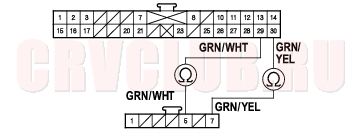
Air Mix Control Motor Test21-21
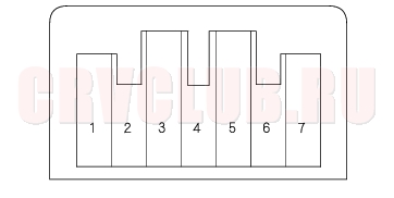
- Disconnect the 7P connector from the air mix control motor.
- Connect battery power to the No. 1 terminal of the air mix control motor, and ground the No. 2 terminal; the air mix control motor should run smoothly, and stop at Max Hot. If it doesn't, reverse the connections; the air mix control motor should run smoothly, and stop at Max Cool. If the air mix control motor does not run, remove it, then check the air mix control linkage and door for smooth movement.
- If the linkage and door move smoothly, replace the air mix control motor.
- If the linkage or door sticks or binds, repair them as needed.
- Measure the resistance between the No. 5 and No. 7 terminals. It should be between 4.2 k to 7.8 k
.
- Reconnect the air mix control motor 7P connector, then turn the ignition switch ON (II).
- Measure the voltage between the No. 3 and No. 7 terminals.
Max Cool - about 1V
Max Hot - about 4V
Air Mix Control Motor Replacement21-21
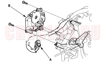
NOTE: LHD type is shown, RHD type is symmetrical.
- RHD type, remove the clutch pedal bracket (M/T) or the parking brake pedal bracket (A/T).
- 2. Disconnect the 7P connector (A) from the air mix control motor (B). Remove the self-tapping screws and the air mix control motor from the heater unit.
- Install the motor in the reverse order of removal. After installation, make sure the motor runs smoothly.
Mode Control Motor Test21-22
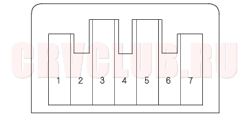
- Disconnect the 7P connector from the mode control motor.
- Connect battery power to the No. 1 terminal of the mode control motor, and ground the No. 2 terminal; the mode control motor should run smoothly, and stop at Vent. If it doesn't, reverse the connections; the mode control motor should run smoothly, and stop at Defrost. When the mode control motor stops running, disconnect battery power immediately.
- If the mode control motor does not run in step 2, remove it, then check the mode control linkage and doors for smooth movement.
- If the linkage and doors move smoothly, replace the mode control motor.
- If the linkage or doors stick or bind, repair them as needed.
- Use a digital multimeter with an output of 1 mA or less at the 20 k
- If there is no continuity for a moment at each terminal, replace the mode control motor.
Mode Control Motor Replacement21-22
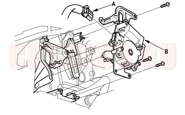
NOTE: LHD type is shown, RHD type is symmetrical.
- Remove the ECM/PCM (see page 11-4) .
- Disconnect the 7P connector (A) from the mode control motor (B). Remove the self-tapping screws and the mode control motor from the heater unit.
- Install the motor in the reverse order of removal. After installation, make sure the motor runs smoothly.
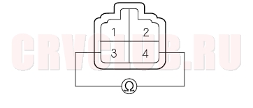
Recirculation Control Motor Test21-23
NOTICE
Incorrectly applying power and ground to the recirculation control motor will damage it. Follow the instructions carefully.
- Connect battery power to the No. 1 terminal of the recirculation control motor, and ground the No. 5 and No. 7 terminals; the recirculation control motor should run smoothly. To avoid damaging the recirculation control motor, do not reverse power and ground. Disconnect the No. 5 or No. 7 terminals from ground; the recirculation control motor should stop at Fresh or Recirculate. Don't cycle the recirculation control motor for a long time.
- If the recirculation control motor does not run in step 2, remove it, then check the recirculation control linkage and doors for smooth movement.
- If the linkage and doors move smoothly, replace the recirculation control motor.
- If the linkage or doors stick or bind, repair them as needed.
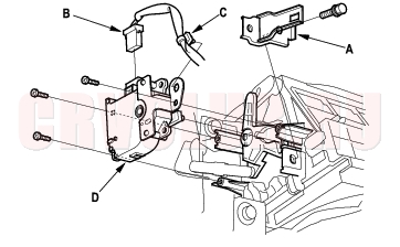
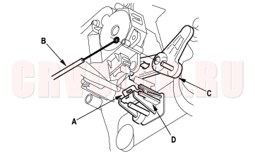
Recirculation Control Motor Replacement21-23
NOTE: LHD type is shown, RHD type is symmetrical.
- Remove the ECM/PCM (see page 11-4) .
- Remove the bolt and the bracket (A). Disconnect the 7P connector (B) and the harness clip (C) from the recirculation control motor (D). Remove the self-tapping screws and the recirculation control motor from the blower unit.
- Install the motor in the reverse order of removal. After installation, make sure the motor runs smoothly.
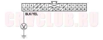
Power Transistor Test21-24
- Disconnect the 4P connector from the power transistor.
- Measure the resistance between the No. 3 and No. 4 terminals of the power transistor. It should be about 1.4 - 1.5 k
- If the resistance is within the specifications, go to step 3.
- If the resistance is not within the specifications, replace the power transistor.
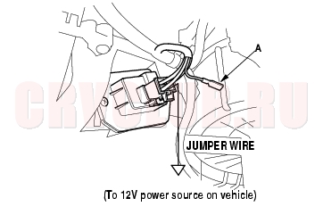
- Carefully release the lock tab on the No. 1 terminal (BLU/YEL) (A) in the 4P connector, then remove the terminal and insulate it from body ground.
- Reconnect the 4P connector to the power transistor.
- Supply 12 volts to the No. 1 cavity with a jumper wire.
- Turn the ignition switch ON (II), and check that the blower motor runs.
- If the blower motor does not run, replace the power transistor.
- If the blower motor runs, the power transistor is OK.
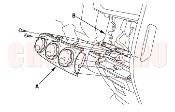
Heater Control Panel Removal and Installation21-24
- Remove the center panel (see page 20-87) .
- Remove the self-tapping screws and the heater control panel (A) from the dashboard (B).
- Install the control panel in the reverse order of removal. After installation, operate the control panel controls to see whether it works properly.
- Run the self-diagnosis function to confirm that there are no problems in the system (see page 21-4) .
Heater Control Panel Bulb Replacement21-25
- Discharge the static electricity (which accumulated on you when you removed the heater control panel) by touching the door striker or other body parts.
- Remove the self-tapping screws, then carefully separate the heater control panel display (A) from the control panel (B). Do not kink or pull on the wires between the display and control panel. Do not touch the electronic components on the printed circuit board in the control panel.
- Remove the bulb(s) with a flat-tip screw driver.
- Install the bulb(s) in the reverse order of removal.
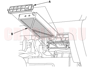
Dust and Pollen Filter Replacement (With Air Conditioning)21-25
NOTE: LHD type is shown, RHD type is symmetrical.
The dust and pollen filters should be replaced every 30,000 km (6,000 miles) or 12 months whichever comes first. Replace the filters more often if the air flow is less than usual.
- Open the glove box. Remove the glove box stop on each side, then hang the glove box down (see page 20-95) .
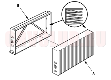
- Remove the filter lid (A) from the blower unit, then pull out the first dust and pollen filter (B). Slide the second filter to the left, and pull it out.
- Remove the filter (A) from the housing (B), and replace the filter.
- Install the filters in the reverse order of removal.
Blower Unit Removal and Installation21-26
NOTE: LHD type is shown, RHD type is symmetrical.
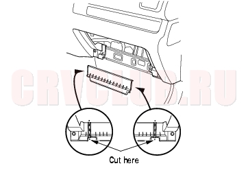
- Remove the passenger's dashboard lower cover (see page 20-95) , the right kick panel (see page 20-76) , and the glove box (see page 20-95) .
- Cut the plastic cross brace in the glove box opening with diagonal cutters in the area shown. Remove and discard the plastic cross brace.
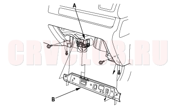
- Remove the relays (A), then remove the bolts and the glove box frame (B).
- Remove the ECM/PCM (see page 11-4) .
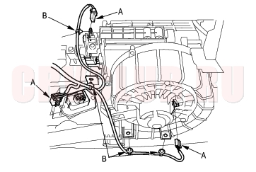
- Disconnect the connectors (A) from the blower motor, the power transistor, and the recirculation control motor, then remove the wire harness clips (B).
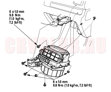
- Fold the carpet and pad back toward you. Remove the mounting bolts, the mounting nut, and the blower unit.
- Install the unit in the reverse order of removal. Make sure that there is no air leakage.
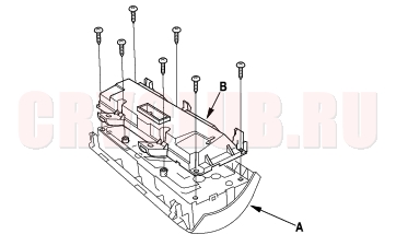
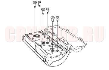
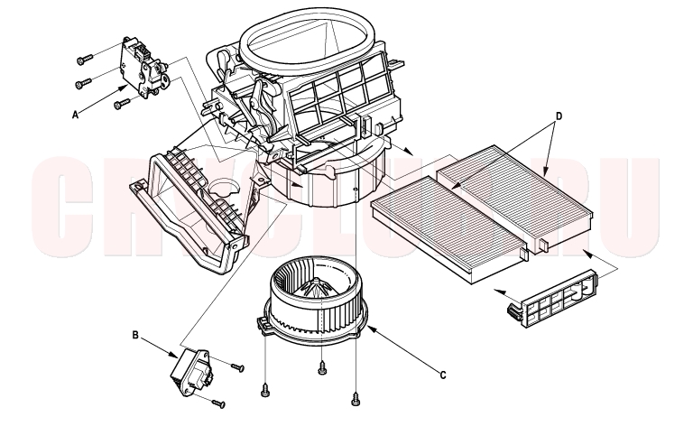
Blower Unit Components Replacement21-27
Note these items when overhauling the blower unit:
The recirculation control motor (A), the power transistor (B), the blower motor (C), and the dust and pollen filters
(with A/C)(D) can be replaced without removing the blower unit.Before reassembly, make sure that the recirculation control linkage and doors move smoothly. After reassembly, make sure the recirculation control motor runs smoothly (see page 21-23) . NOTE: LHD type is shown, RHD type is symmetrical.
Heater Unit/Core Replacement21-28
SRS components are located in this area. Review the SRS component locations (see page 23-14) , and precautions and procedures (see page 23-16) in the SRS section before performing repairs or service.
NOTE: LHD type is shown, RHD type is symmetrical.
- Make sure you have the anti-theft code for the radio, then write down the frequencies for the radio's preset buttons.
- Disconnect the negative cable from the battery.
- With air conditioning; disconnect the A/C line from the evaporator core (see page 21-45) .
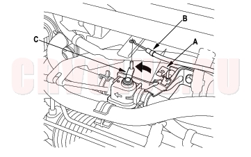
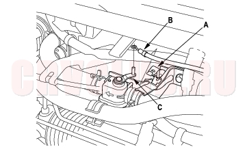
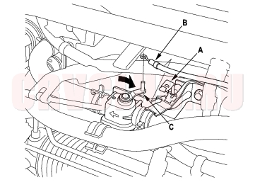
- From under the hood, open the cable clamp (A), then disconnect the heater valve cable (B) from the heater valve arm (C). Turn the heater valve arm to the fully opened position as shown.
- When the engine is cool, drain the engine coolant from the radiator (see page 10-6) .
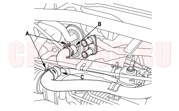
- Slide the hose clamps (A) back, then disconnect the inlet heater hose (B) and the outlet heater hose (C) from the heater core. Engine coolant will run out when the hoses are disconnected; drain it into a clean drip pan. Be sure not to let coolant spill on the electrical parts or the painted surfaces. If any coolant spills, rinse it off immediately.
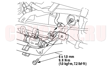
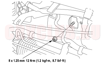
- Remove the mounting bolt and the heater valve as shown.
21-29
- Remove the mounting nut from the heater unit. Take care not to damage or bend the fuel lines and the brake lines, etc.
- Remove the dashboard (see page 20-96) .
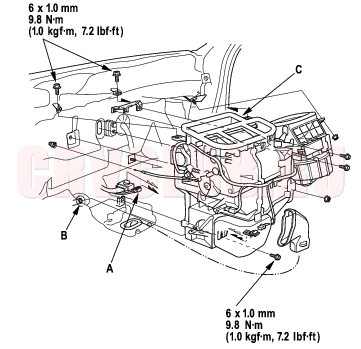
- Remove the ECM/PCM (see page 11-4)
- Disconnect the connectors (A) from the heater unit, then disconnect the drain hose (B). Remove the mounting bolts and nuts, then remove the heater unit/Core (C).
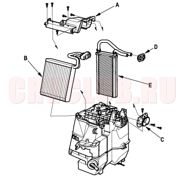
- Remove the self-tapping screws and the expansion valve cover (A). With air conditioning; carefully pull out the evaporator core (B) so you don't bend the inlet and outlet pipes. Remove the self-tapping screws and the flange cover (C), then remove the grommet (D), and carefully pull out the heater core (E) so you don't bend the inlet and outlet pipes.
- Install the heater core and the evaporator core (with A/C) in the reverse order of removal.
- Install the heater unit in the reverse order of removal, and note these items:
- Do not interchange the inlet and outlet heater hoses, and install the hose clamps securely.
- Refill the cooling system with engine coolant (see page 10-6) .
- Be sure to connect the drain hose securely.
- Adjust the heater valve cable (see page 21-30) .
- Make sure that there is no coolant leakage.
- Make sure that there is no air leakage.
- With air conditioning, refer to evaporator core replacement (see step 6 on page 21-45 ).
Heater Valve Cable Adjustment21-30
NOTE: LHD type is shown, RHD type is symmetrical.
- From under the hood, open the cable clamp (A), then disconnect the heater valve cable (B) from the heater valve arm (C).
- From under the dash, disconnect the heater valve cable housing from the cable clamp (A), and disconnect the heater valve cable (B) from the air mix control linkage (C).
- Set the temperature control dial on Max Cool with the ignition switch ON (II).
- Attach the heater valve cable (B) to the air mix control linkage (C) as shown above. Hold the end of the heater valve cable housing against the stop (D), then snap the heater valve cable housing into the cable clamp (A).
- From under the hood, turn the heater valve arm (C) to the fully closed position as shown, and hold it. Attach the heater valve cable (B) to the heater valve arm, and gently pull on the heater valve cable housing to take up any slack, then install the heater valve cable housing into the cable clamp (A).
|
HVAC 21-1
Heating21-2 |