Charging System04-24
|
Engine Electrical04-1
Charging System04-24 |
Charging System04-24
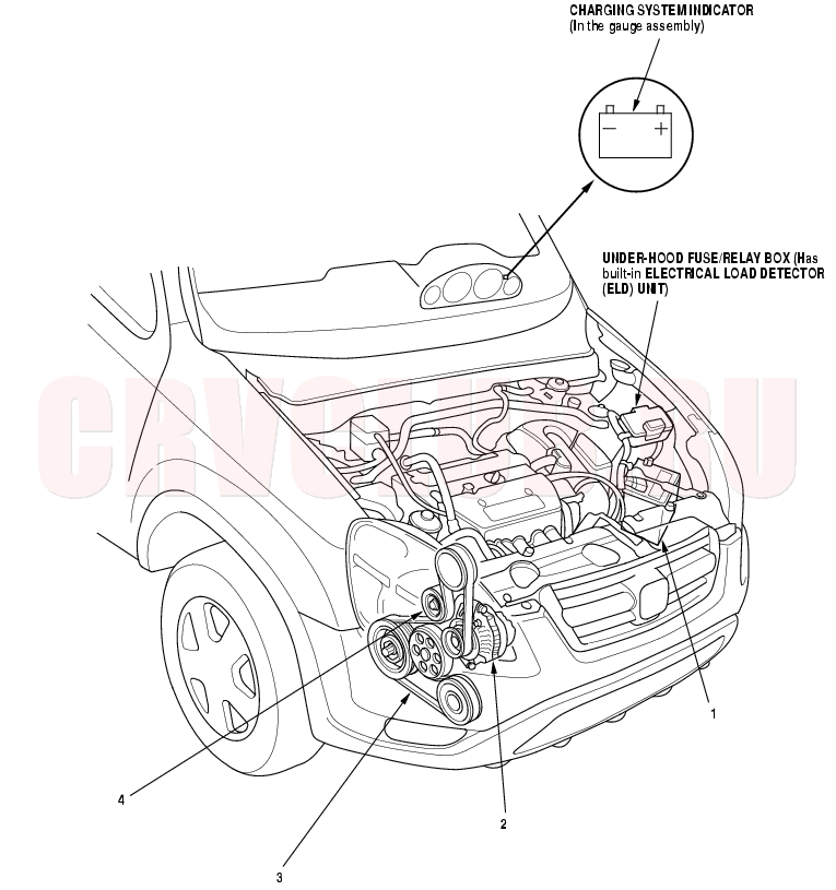
Component Location Index
Test, page 22A-59 Troubleshooting, page 04-26 ; Replacement, page 04-32 ; Overhaul, page 04-34 Inspection, page 04-29 ; Replacement, page 04-30 Inspection, page 04-30 ; Replacement, page 04-31
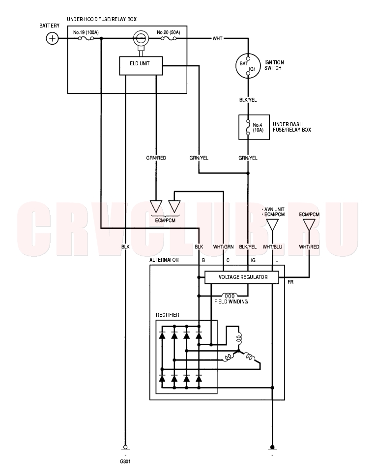
Circuit Diagram04-25
Charging Circuit Troubleshooting04-26
If the charging system indicator does not come on or does not go off, or the battery is dead or low, test the following items in the order listed below:
Battery (see page 22A-59)
Charging system indicator
Alternator and regulator circuit
Alternator control systemCharging System Indicator Test
Does the charging system indicator come on?
Yes : Go to step 2.
No : Go to step 3.
Does the charging system indicator go off?
Yes : Charging system indicator circuit is OK.

No : Go to step 3.
- Turn the ignition switch OFF.
- Troubleshoot the multiplex control system (see page 22A-231) .
Is the multiplex control system OK?
Yes : Without navigation system. Go to step 7.
Yes : With navigation system. Go to step 5.
No : Check the multiplex control system as indicated by the Diagnostic Trouble Code (DTC) (see step 8 on page 22A-232).
Does the charging system indicator go off?
Yes : Check that the terminals are firmly seated at the connectors. If OK, substitute a known-good AVN unit and recheck.
No : Go to step 7.
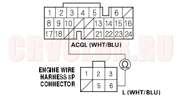
- Disconnect the engine wire harness 6P connector from the starter sub-harness 6P connector.
- Measure the voltage at the No. 3 terminal of the engine wire harness 6P connector with the ignition switch ON (II).
Is there battery voltage?
Yes : Go to step 9.
No : Check for a blown No.4 (10A) fuse in the under-dash fuse/relay box. If the fuse is OK, repair open in the wire between the alternator and the under-dash fuse/relay box.
- Turn the ignition switch OFF.
- Disconnect the negative cable from the battery.
- Disconnect Engine Control Module (ECM)/Powertrain Control Module (PCM) connector B (24P).
04-27
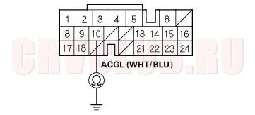
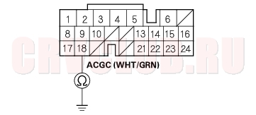
- Check continuity between the ECM/PCM connector terminal B10 and engine wire harness 6P connector terminal No. 6.
Is there continuity?
Yes : Go to step 13.
No : Repair open in the wire between the alternator and the ECM/PCM.
Is there continuity?
Yes : Repair short in the wire between the alternator and the ECM/PCM.
No : Reconnect the negative cable to the battery, and go to alternator and regulator test.
Alternator and Regulator Circuit Test
- Be sure the battery is sufficiently charged and in good condition (see page 22A-59) .
- Raise the hoist to full height.
- Hook up the ammeter, 0 - 400 A, to the starter sub-harness.
- Lower the hoist.
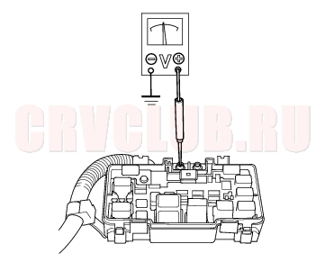
- Hook up the voltmeter, 0 - 20 V (accurate within 0.1 V), to T101.
Charging Circuit Troubleshooting (cont'd)04-28
- Start the engine. Hold the engine at 3,000 rpm (min-1) with no load (in Park or Neutral) until the radiator fan comes on then let it idle.
- Raise the engine speed to 2,000 rpm (min-1) and hold it there.
- Turn the headlights (high beam) on, and measure voltage at the under-hood fuse/relay box terminal.
Is the voltage between 13.9 and 15.1 V?
Yes : Go to step 9.
No : Repair or replace the alternator (see page 04-34).
- Read the amperage at 13.5 V.
- NOTE: Adjust the voltage by turning the blower motor, rear window defogger, brake lights, etc. ON.
Is the amperage 60A or more?
Yes : Alternator/regulator operation is OK.
No : Repair or replace the alternator (see page 04-34).
Alternator Control System Test
- Check for proper operation of the Electrical Load Detector (ELD) by checking the Malfunction Indicator Lamp (MIL) (see page 11-3) .
- Disconnect the engine wire harness 6P connector from the starter sub-harness 6P connector.
- Start the engine, and turn the headlights (high beam) ON.
- Measure voltage between the engine wire harness 6P connector terminal No. 2 and the positive terminal of the battery.
Is there 1 V or less?
Yes : Go to step 9.
No : Go to step 5.
- Turn the headlights and ignition switch OFF.
- Disconnect the negative cable from the battery.
- Disconnect ECM/PCM connector B (24P).
04-29
Is there continuity?
Yes : Repair short in the wire between the alternator and the ECM/PCM.
No : Check that the terminals are firmly seated at the connector. If OK, substitute a known-good ECM/PCM, and recheck (see page 11-5).
If the prescribed voltage is now available, replace the original ECM/PCM.
- Turn the headlights and ignition switch OFF.
- Disconnect the negative cable from the battery.
- Disconnect ECM/PCM connector B (24P).
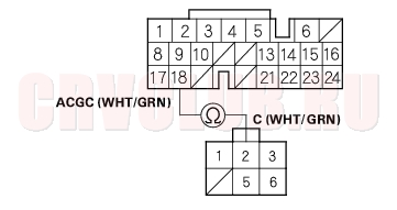
- Check for continuity between ECM/PCM connector terminal B18 and engine wire harness 6P connector terminal No. 2.
Is there continuity?
Yes : Repair or replace the alternator (see page 04-34).
No : Repair open in the wire between the alternator and the ECM/PCM.
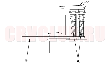
Drive Belt Inspection04-29
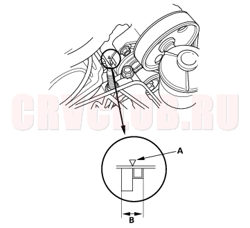
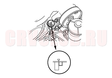
Check that the auto-tensioner indicator (A) is within the standard range (B) as shown. If it is out of the standard range, replace the drive belt (see page 04-30) .
Drive Belt Replacement04-30
- Remove the splash shield (see step 21 on page 05-6 ).
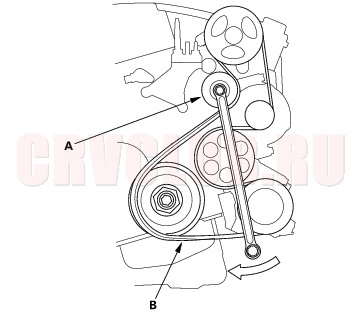
- Move the auto-tensioner (A) to relieve tension from the drive belt (B), and remove the drive belt.
- Install the new belt in the reverse order of removal.
Drive Belt Auto-tensioner Inspection04-30
- Check whether there is a change in the position of the auto-tensioner indicator before starting the engine and after starting the engine. If there is a change in the position, replace the auto-tensioner.
- Check for abnormal noise from the tensioner pulley. If abnormal noise is heard, replace the tensioner pulley.
- Remove the drive belt (see page 04-30) .
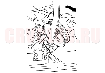
- Move the auto-tensioner within its limit with the belt tension release tool in the direction shown. Check that the tensioner moves smoothly and without any abnormal noise. If the tensioner does not move smoothly or there is abnormal noise, replace the auto-tensioner.
04-31
- Remove the auto-tensioner (see page 04-31) .
- Install the tensioner pulley.
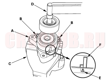
- Clamp the auto-tensioner (A) by using two 8 mm bolts (B) and a vise (C) as shown. Do not clamp the auto-tensioner itself.
- Set the torque wrench (D) on the pulley bolt.
- Align the indicator (E) on the tensioner base with center mark (F) on the tensioner arm by using the torque wrench, and measure the torque. If the torque value is out of specification, replace the auto-tensioner.
- NOTE: If the indicator exceeds the center mark, recheck the torque.
Auto-tensioner spring torque:
26.5 - 36.3 N·m (2.7 - 3.7 kg·m, 19.5 - 26.8 lbf·ft)
Drive Belt Auto-tensioner Replacement04-31
- Remove the drive belt (see page 04-30) .
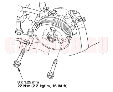
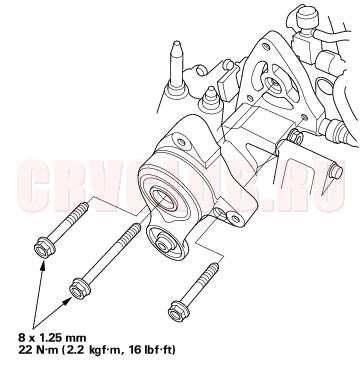
- Remove the Power Steering (P/S) pump without disconnecting the P/S hoses.
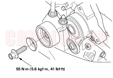
- Remove the tensioner pulley.
Drive Belt Auto-tensioner Replacement (cont'd)04-32
Alternator Replacement04-32
- Disconnect the battery negative cable, then disconnect the positive cable.
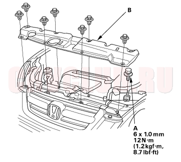
- Remove the bolt (A) securing the battery clamp, then remove the bulkhead cover (B).
- Remove the upper bracket and cushion.
- Remove the drive belt (see page 04-30) .
- Remove the auto-tensioner (see page 04-31) .
04-33
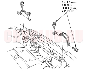
- Remove the gasket (A), then remove the Positive Crankcase Ventilation (PCV) valve holder (B) with a hex wrench.
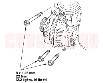
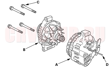
- Remove the three bolts securing the alternator.
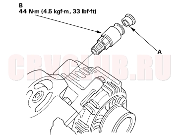
- Disconnect the alternator connector (A), BLK wire (B) and harness clamp (C) from the alternator.
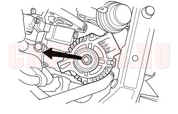
- Remove the alternator.
- Install the alternator and drive belt in the reverse order of removal.
- Apply liquid gasket to the PCV valve holder threads, then install the PCV valve holder.
- Install the upper bracket and cushion. Make sure they are set securely.
- Connect the battery positive cable and negative cable to the battery.
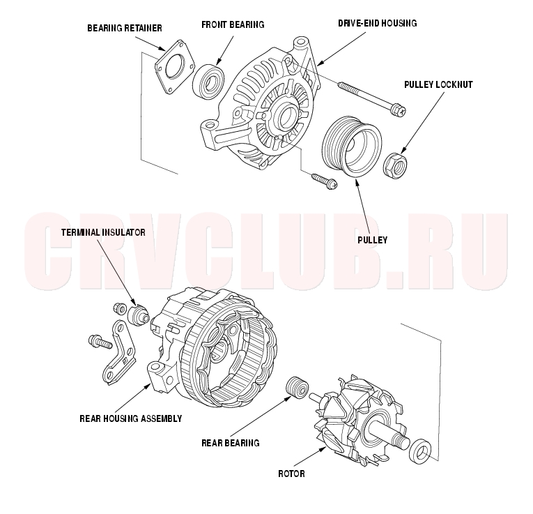
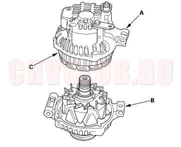
Alternator Overhaul04-34
Exploded View
04-35
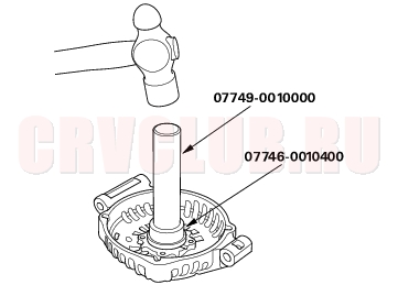
Special Tools Required
Handle driver 07749-0010000 Driver attachment, 52 x 55 mm 07746-0010400 NOTE: Refer to the Exploded View as needed during this procedure.
- Test the alternator and regulator before you remove them (see page 04-26) .
- Remove the alternator (see page 04-32) .
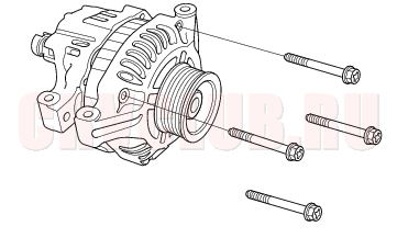
- Remove the four through bolts.
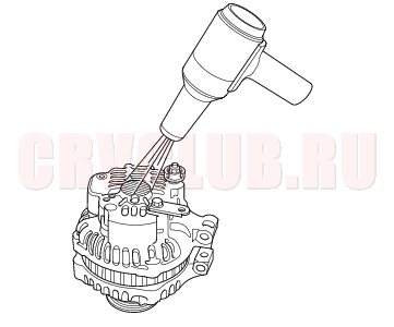
- Heat the rear bearing seat with a 1,000 W hair drier for about 5 minutes (50 - 60°C, 129 - 140°F).
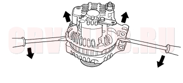
- Separate the rear housing from the drive-end housing by inserting a flat tip screwdriver into the openings and prying them apart.
- NOTE: Be careful not to damage the stator with the tip of the screwdriver.
- Separate the rear housing (A) and drive-end housing (B) with the stator (C) attached to the rear housing.
Alternator Overhaul (cont'd)04-36
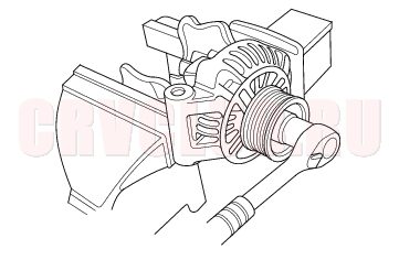
- If you are not replacing the front bearing and/or rear bearing, go to step 15. Clamp the rotor in a soft-jawed vise, then remove the pulley locknut.
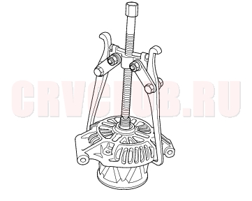
- Remove the rotor using a puller as shown.
- Inspect the rotor shaft for scoring, and inspect the bearing journal surface in the drive-end housing for seizure marks.
- If either the rotor or drive-end housing is damaged, replace the alternator.
- If both the rotor and the drive-end housing are OK, go to step 10.
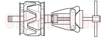
- Remove the rear bearing using the puller as shown.
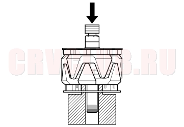
- Use a hand press to install the new rear bearing. Apply pressure only on the inner race to avoid damaging the bearing.
04-37
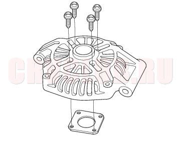
- Remove the front bearing retainer plate.
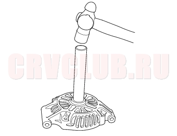
- Support the drive-end housing in a vise, and drive out the front bearing with a brass drift and hammer.
- With a hammer and the special tools, install a new front bearing in the drive-end housing.
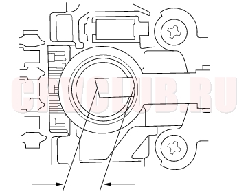
Alternator Brush Inspection
- Measure the length of both brushes with a vernier caliper.
- If either brush is shorter than the service limit, replace the rear housing assembly.
- If brush length is OK, go to step 16.
Alternator Brush Length:
Standard (New): 19.0 mm (0.75 in.)
Service Limit: 5.0 mm (0.2 in.)
Alternator Overhaul (cont'd)04-38
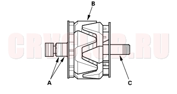
Rotor Slip Ring Test
- Check that there is continuity between the slip rings (A).
- If there is continuity, go to step 17.
- If there is no continuity, replace the rotor assembly.
- Check that there is no continuity between each slip ring (A) and the rotor (B) and the rotor shaft (C).
- If there is no continuity, replace the rear housing assembly, go to step 18.
- If there is continuity, replace the rotor assembly.
Alternator Reassembly
- If you removed the pulley, put the rotor in the drive-end housing, then tighten its locknut to 111 N·m (11.3 kgf·m, 81.7 lbf·ft).
- Remove any grease or any oil from the slip rings.
- Push the brushes (A) in, then insert a pin or drill bit (B) (about 1.8 mm (0.77 in.) diameter) to hold them there.
- Heat the rear bearing seat with a 1,000 W hair drier for about 5 minutes (50 - 60°C, 129 - 140°F).
- Put the rear housing assembly (A) and drive-end housing/rotor assembly (B) together, tighten the four through bolts (C) and pull out the pin (D).
- After assembling the alternator, turn the pulley by hand to make sure the rotor rotates smoothly and without noise.
- Install the alternator and drive belt (see page 04-32) .
|
Engine Electrical04-1
Charging System04-24 |