Cruise Control04-39
|
Engine Electrical04-1
Cruise Control04-39 |
Cruise Control04-39
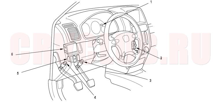
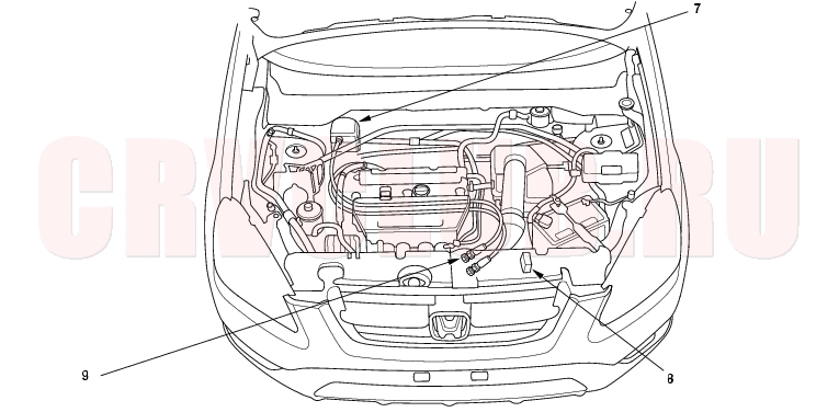
Component Location Index
Test/Replacement, page 04-46 Test, page 22A-99 ; Pedal Height Adjustment, page 19A-5 Test, page 04-49 ; Clutch Pedal Adjustment, page 12-4 Test/Replacement, page 04-46 Input Test, page 04-44
Test, page 04-47 ; Replacement, page 04-48 Test, page 14-168 Adjustment, page 04-49
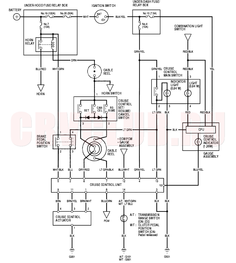
Circuit Diagram04-40
Symptom Troubleshooting Index04-41
The numbers in the table show the troubleshooting sequence. Before troubleshooting.
check the No. 10 (7.5A) and No. 4 (10A) fuses in the under-dash fuse/relay box, and the No. 7 (15A) fuse in the under-hood fuse/relay box. check that the horn sounds. check the tachometer to see if it works properly.
Cruise control cannot be set
- Check main switch (see page 04-46)
- Check SET/RESUME/CANCEL switch (see page 04-46)
- Test brake pedal position switch (see page 22A-99) and check its adjustment (see page 19A-5 )
- Test clutch pedal position switch (see page 04-49) and check its adjustment (M/T) (see page 12-4)
- Check transmission range switch (A/T) (see page 14-168)
- Check control unit (see page 04-44)
Poor ground: G101 (A/T), G501 (M/T) Open circuit, loose or disconnected terminals: LT GRN, GRN/YEL, GRY/RED, BLU, WHT/GRN (A/T), LT BLU
(M/T), BLU/WHTCruise control can be set but indicator light does not go on
- Check cruise control indicator bulb in gauge assembly (see page 22A-73)
- Check control unit (see page 04-44)
Poor ground: G501 Open circuit, loose or disconnected terminals: YEL, BLU/YEL Cruise speed is noticeably higher or lower than what was set
- Check Vehicle Speed Sensor (VSS) (see page 22A-75)
- Check actuator (see page 04-47)
- Check control unit (see page 04-44)
Excessive overshooting or undershooting when trying to set speed
- Check actuator (see page 04-47)
- Check Vehicle Speed Sensor (VSS) (see page 22A-75)
- Check control unit (see page 04-44)
Speed fluctuation on a flat road with cruise control set
- Check Vehicle Speed Sensor (VSS) (see page 22A-75)
- Check actuator (see page 04-47)
- Check control unit (see page 04-44)
Vehicle does not decelerate or accelerate accordingly when SET/RESUME/CANCEL button is pushed
- Check SET/RESUME/CANCEL switch (see page 04-46)
- Check control unit (see page 04-44)
Open circuit, loose or disconnected terminals: GRY/RED, LT GRN/BLK Set speed not cancelled (engine rpm stays high) when clutch pedal is pushed (M/T)
- Test clutch pedal position switch (see page 04-49) and check its adjustment (see page 12-4)
- Check control unit (see page 04-44)
Short to ground in the LT BLU wire Set speed not cancelled when shift lever is moved to Neutral position (A/T)
- Check transmission range switch (see page 14-168)
- Check control unit (see page 04-44)
Short to ground in the WHT/ GRN wire Set speed not cancelled when brake pedal is pushed
- Test brake pedal position switch (see page 22A-99) and check its adjustment (see page 19A-5)
- Check control unit (see page 04-44)
Open circuit, loose or disconnected terminals: WHT/BLK
Symptom Troubleshooting Index (cont'd)04-42
Set speed, does not cancel when main switch is pushed OFF
- Check main switch (see page 04-46)
- Check control unit (see page 04-44)
Short to power in the LT GRN wire. Set speed, does not cancel when CANCEL button is pushed
- Check SET/RESUME/CANCEL switch (see page 04-46)
- Check control unit (see page 04-44)
Open circuit, loose or disconnected terminals: GRY/RED, LT GRN/BLK Set speed will not resume when RESUME button is pushed (with main switch on, when set speed is temporarily cancelled by pressing the brake pedal)
- Check SET/RESUME/CANCEL switch (see page 04-46)
- Check control unit (see page 04-44)
Open circuit, loose or disconnected terminals: LT GRN/BLK The transmission shifts down slower than normal when going up a hill with the cruise control on (A/T)
- Troubleshoot the cruise control communication circuit (see page 04-43)
Open circuit, loose or disconnected terminals: BLU/ORN
Cruise Control Communication Circuit Troubleshooting04-43
- Start the engine.
- Turn on the cruise control main switch, then drive the vehicle to speeds over 25 mph (40 km/h) with the cruise control.
Does the cruise control operate?
Yes : Go to step 3.
No : Check the cruise control unit (see page 04-44) or cruise control actuator.

- Turn the ignition switch OFF.
- Disconnect the negative cable from the battery.
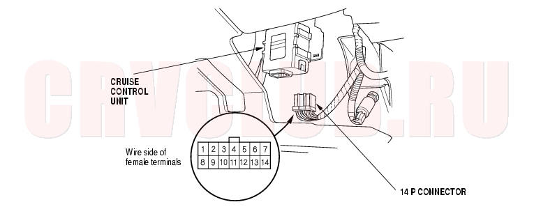
- Disconnect Powertrain Control Module (PCM) connector D (17P) and cruise control unit 14P connector.
- Check for continuity between PCM connector terminal D12 and body ground.
Is there continuity?
Yes : Repair short to ground in the wire between PCM connector terminal D12 and the cruise control unit 14P connector terminal No. 8.
No : Go to step 7.
- Reconnect PCM connector D (17P) and the cruise control unit 14P connector.
- Connect the negative cable to the battery.
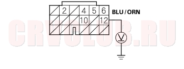
- Connect a voltmeter between cruise control unit 14P connector terminal No. 8 and body ground. Test-drive the vehicle at speeds over 25 mph (40 km/h) with the cruise control set, and watch the voltmeter.
Is there about 1 V?
Yes : Go to step 10.
No : Substitute a known-good cruise control unit. If the system works properly, replace the cruise control unit.
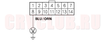
- Connect a voltmeter between PCM connector terminal D12 and body ground. Drive the vehicle at speeds over 25 mph (40 km/h) with the cruise control set, and watch the voltmeter.
Is there about 1 V?
Yes : Check for loose connectors of the BLU/ORN wire between the cruise control unit and the PCM. If necessary replace the PCM and recheck (see page 11-4).
No : Repair open in the wire between PCM connector terminal D12 and the control unit 14P connector terminal No. 8.
Control Unit Input Test04-44
SRS components are located in this area. Review the SRS component locations (see page 23-14) and precautions and procedures (see page 23-16) in the SRS section before performing repairs or service.
- Disconnect the 14P connector from the control unit.
- Inspect the connector and socket terminals to be sure they are all making good contact.
- If the terminals are bent, loose, or corroded, repair them as necessary, and recheck the system.
- If the terminals look OK, go to step 3.
- With the 14P connector disconnected, make these input tests.
04-45
- If any test indicates a problem, find and correct the cause, then recheck the system. If all the input tests prove OK, the control unit may be faulty. Substitute a known-good control unit and retest. If the system works properly, replace the control unit.
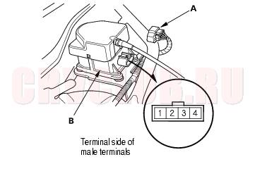
Main Switch Test/Replacement04-46
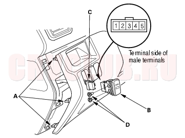
- Detach the three clips (A), to create clearance between the dashboard and dashboard panel.
- Release the clips of the main switch, and push the main switch (B) out of the panel, then disconnect the 5P connector (C) from the main switch.
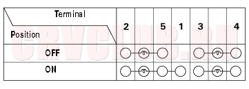
- Check for continuity between the terminals in each switch position according to the table. If there is no continuity, replace the illumination bulbs (D) or the switch.
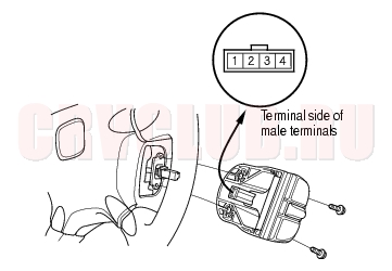
Set/Resume/Cancel Switch Test/Replacement04-46
- Remove the two screws, then remove the switch.
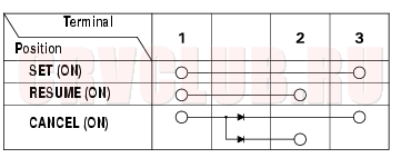
- Check for continuity between the terminals in each switch position according to the table.
- If there is continuity, and it matches the table, but switch failure occurred on the cruise control unit input test, check and repair the wire harness on the switch circuit.
- If there is no continuity in one or both positions, replace the switch.
Actuator Test04-47
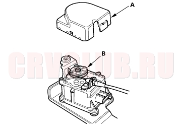
- Disconnect the 4P connector (A) from the actuator (B).
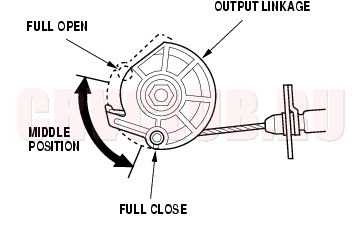
- Remove the cover (A), and check the output linkage (B) for smooth movement.
- Connect battery power to the No. 2 terminal and ground to the No. 1 terminal.
- Check for a clicking sound from the magnetic clutch. The output linkage should be locked.
- If the output linkage is not locked, replace the actuator assembly.
- Check the operation of the actuator motor in each output linkage position according to the table. You should be able to hear the motor.
- If the actuator motor does not operate as specified, replace the actuator assembly.
Actuator/Cable Replacement04-48
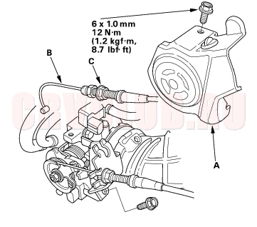
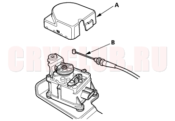
- Remove the throttle cable cover (A), fully open the cruise control link by hand, then remove the cruise control cable (B) from link. Loosen the locknut (C), and remove the cable from the bracket.
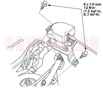
- Disconnect the 4P connector, and remove the two bolts securing the actuator.
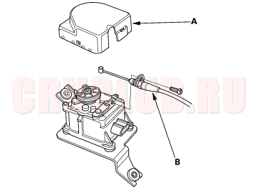
- Remove the actuator cover (A), then remove the actuator cable (B) from the actuator.
- Install in the reverse order of removal, and adjust the free play at the throttle linkage after connecting the actuator cable.
Actuator Cable Adjustment04-49
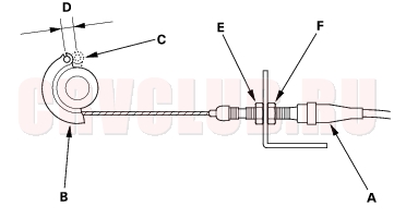
- Check that the actuator cable (A) moves smoothly with no binding or sticking.
- Measure the amount of movement of the output linkage (B) until the engine speed starts to increase. At first, the output linkage should be located at the fully closed position (C). The free play (D) should be 3.75 ± 0.5 mm (0.15 ± 0.02 in.).
- If the free play is not within specs, loosen the locknut (E), and turn the adjusting nut (F) until the free play is as specified, then retighten the locknut.
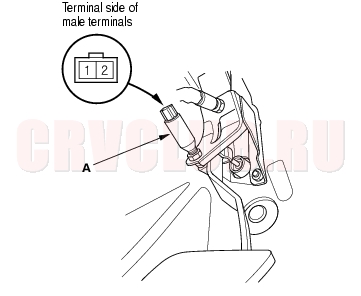
Clutch Pedal Position Switch Test04-49
- Remove the clutch pedal position switch.
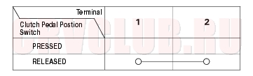
- Check for continuity between the terminals according to the table.
- If the continuity is not as specified, replace the clutch pedal position switch.
- If OK, install the clutch pedal position switch and adjust the pedal height (see page 12-4) .
|
Engine Electrical04-1
Cruise Control04-39 |