Idle Control System11-139
|
Fuel and Emissions11-1
Idle Control System11-139 |
Idle Control System11-139
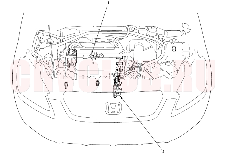
Component Location Index
*: The illustration shows LHD model.
Troubleshooting, page 11-145 Troubleshooting, page 11-140
DTC Troubleshooting11-140
DTC P1519 (14-3): IAC Valve Circuit Malfunction
- Reset the ECM/PCM (see page 11-4) .
- Turn the ignition switch ON (II).
Is DTC P1519 indicated?
Yes : Go to step 3.
No : Intermittent failure, system is OK at this time. Check for poor connections or loose wires at the IAC valve and at the ECM/PCM.

- Turn the ignition switch OFF.
- Disconnect the IAC valve 3P connector.
- Turn the ignition switch ON (II).
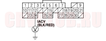
- Measure voltage between IAC valve 3P connector terminal No. 2 and body ground.
Is there battery voltage?
Yes : Go to step 7.
No : Repair open in the wire between the IAC valve and the PGM-FI main relay.
- Turn the ignition switch OFF.
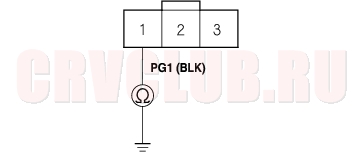
- Check for continuity between body ground and IAC valve 3P connector terminal No. 1.
Is there continuity?
Yes : Go to step 9.
No : Repair open in the wire between the IAC valve and G101.
- Disconnect the negative cable from the battery.
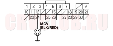
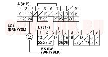
- Disconnect ECM/PCM connector A (31P).
- Check for continuity between body ground and ECM/PCM connector terminal A12.
Is there continuity?
Yes : Repair short in the wire between the IAC valve and the ECM/PCM (A12).
No : Go to step 12.
11-141
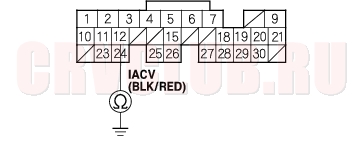
Is there continuity?
Yes : Go to step 14.
No : Repair open in the wire between the IAC valve and the ECM/PCM (A12).
- Reconnect the IAC valve 3P connector.
- Reconnect the negative cable to the battery.
- Turn the ignition switch ON (II).
- Measure voltage between body ground and ECM/PCM connector terminal A12.
Is there battery voltage?
Yes : Substitute a known-good ECM/PCM and recheck (see page 11-5). If symptom/indication goes away, replace the original ECM/PCM.
No : Replace the IAC valve.
A/C Signal Circuit Troubleshooting11-142
- Turn the ignition switch ON (II).
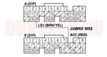
- Momentarily connect ECM/PCM connector terminals A24 and E18 with a jumper wire several times.
Is there a clicking noise from the A/C compressor clutch?
Yes : Go to step 3.
No : Go to step 6.
Does the A/C operate?
Yes : The air conditioning signal is OK.
No : Substitute a known-good ECM/PCM and recheck (see page 11-5). If symptom/indication goes away, replace the original ECM/PCM.
- Momentarily connect the under-hood fuse/relay box 14P connector terminal No. 10 to body ground with a jumper wire several times.
Is there clicking noise from the A/C compressor clutch?
Yes : Repair open in the wire between the ECM/PCM (E18) and the A/C clutch relay.
No : Check the A/C system for other symptoms.
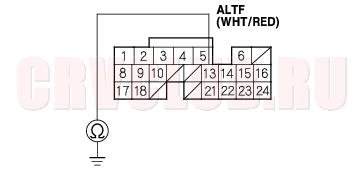
Alternator FR Signal Circuit Troubleshooting11-143
- Disconnect the alternator 4P connector.
- Turn the ignition switch ON (II).
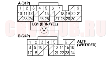
- Measure voltage between ECM/PCM connector terminals A24 and B13.
Is there about 5 V?
Yes : Go to step 4.
No : Go to step 14.
- Turn the ignition switch OFF.
- Reconnect the alternator 4P connector.
- Start the engine. Hold the engine at 3,000 rpm (min-1) with no load (in Park or neutral) until the radiator fan comes on, then let it idle.
- Measure voltage between ECM/PCM connector terminals A24 and B13.
Does the voltage decrease when the headlights and rear window defogger are turned on?
Yes : The alternator FR signal is OK.
No : Go to step 8.
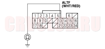
- Turn the ignition switch OFF.
- Disconnect the negative cable from the battery.
- Disconnect ECM/PCM connector B (24P).
- Disconnect the alternator 4P connector.
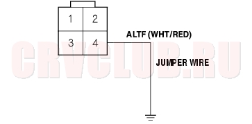
- Connect alternator 4P connector terminal No. 4 and body ground with a jumper wire.
Is there continuity?
Yes : Test the alternator (see page 04-27).
No : Repair open in the wire between the ECM/PCM (B13) and the alternator.
- Turn the ignition switch OFF.
- Disconnect the negative cable from the battery.
- Disconnect ECM/PCM connector B (24P).
Alternator FR Signal Circuit Troubleshooting (cont'd)11-144
Is there continuity?
Yes : Repair short in the wire between the ECM/PCM (B13) and the alternator.
No : Substitute a known-good ECM/PCM and recheck (see page 11-5). If symptom/indication goes away, replace the original ECM/PCM.
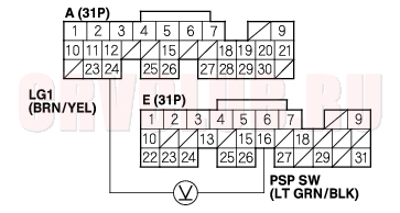
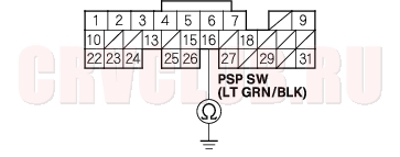
PSP Switch Signal Circuit Troubleshooting11-145
Is there less than 1.0 V?
Yes : Go to step 3.
No : Go to step 6.
- Start the engine.
- Turn the steering wheel to the full lock position.
- Measure voltage between ECM/PCM connector terminals A24 and E16.
Is there battery voltage?
Yes : The PSP switch signal is OK.
No : Go to step 13.
- Turn the ignition switch OFF.
- Disconnect the PSP switch 2P connector.
- Turn the ignition switch ON (II).
- At the harness side, connect PSP switch 2P connector terminals No. 1 and No. 2 with a jumper wire.
Is there less than 1.0 V?
Yes : Replace the PSP switch.
No : Go to step 11.
- Turn the ignition switch OFF.
- Check for continuity between PSP switch 2P connector terminal No. 2 and body ground.
Is there continuity?
Yes : Repair open in the wire between the PSP switch and ECM/PCM (E16).
No : Repair open in the wire between the PSP switch and G301.
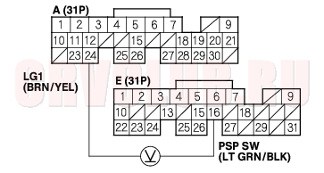
- Turn the ignition switch OFF.
- Disconnect the PSP switch 2P connector.
- Turn the ignition switch ON (II).
PSP Switch Signal Circuit Troubleshooting (cont'd)11-146
Is there battery voltage?
Yes : Replace the PSP switch.
No : Go to step 17.
- Turn the ignition switch OFF.
- Disconnect the negative cable from the battery.
- Disconnect ECM/PCM connector E (31P).
- Check for continuity between body ground and ECM/PCM connector terminal E16.
Is there continuity?
Yes : Repair short in the wire between ECM/PCM (E16) and the PSP switch.
No : Substitute a known-good ECM/PCM and recheck (see page 11-5). If symptom/indication goes away, replace the original ECM/PCM.
Brake Pedal Position Switch Signal Circuit Troubleshooting11-146
Are the brake lights on without pressing the brake pedal?
Yes : Inspect the brake pedal position switch
(see page 19A-5).
No : Go to step 2.
Do the brake lights come on?
Yes : Go to step 3.
No : Go to step 4.
Is there battery voltage?
Yes : The brake pedal position switch signal is OK.
No : Repair open in the wire between the ECM/PCM (E22) and the brake pedal position switch.
11-147
Is the fuse OK?
Yes : Repair open in the wire between the brake pedal position switch and the No. 7 HORN, STOP (15A) fuse. Inspect the brake pedal position switch (see page 19A-5).
No : Repair short in the wire between the ECM/PCM (E22) and the No. 7 HORN, STOP (15A) fuse. Replace the No. 7 HORN, STOP (15A) fuse.
Idle Speed Inspection11-148
Leave the Idle Air Control (IAC) valve connected. Before checking the idle speed, check these items:
The Malfunction Indicator Lamp (MIL) has not been reported on. Ignition timing Spark plugs Air cleaner PCV system
- Disconnect the Evaporative Emission (EVAP) canister purge valve 2P connector.
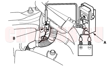
- Connect a tachometer (A) to the test tachometer connector (B).
- Start the engine. Hold the engine at 3,000 rpm (min-1) with no load (in Park or neutral) until the radiator fan comes on, then let it idle.
- Check the idle speed with no-load conditions: headlights, blower fan, rear defogger, radiator fan, and air conditioner are not operating.
Idle speed should be:
M/T 650 ± 50 rpm (min-1) A/T 650 ± 50 rpm (min-1) (in Park or neutral)
- Idle the engine for 1 minute with heater fan switch on HI and air conditioner on, then check the idle speed.
Idle speed should be:
M/T 700 ± 50 rpm (min-1) A/T 700 ± 50 rpm (min-1) (in Park or neutral)
- NOTE: If the idle speed is not within specification,
go to the Symptom Troubleshooting Index.- Reconnect the EVAP canister purge valve 2P connector.
- NOTE: You can use the scan tool or Honda PGM Tester to inspect idle speed.
|
Fuel and Emissions11-1
Idle Control System11-139 |