VTEC/VTC11-123
|
Fuel and Emissions11-1
VTEC/VTC11-123 |
VTEC/VTC11-123
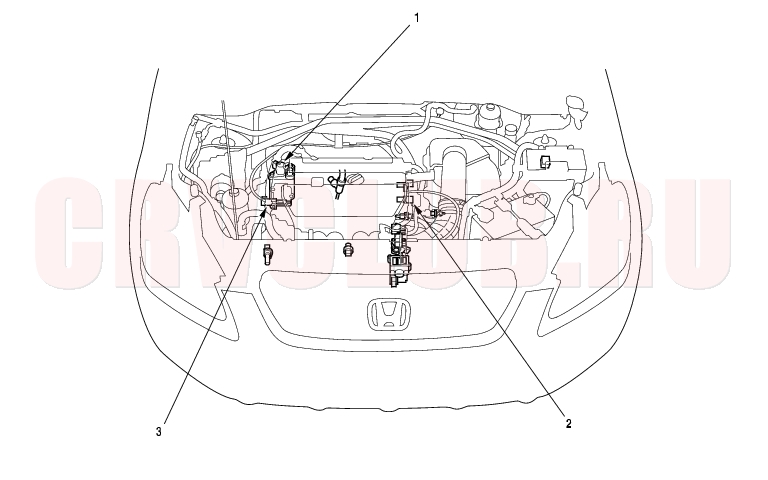
Component Location Index
*: The illustration shows LHD model
DTC Troubleshooting11-124
DTC P0010 (56-1): VTC Oil Control Solenoid Valve Malfunction
- Reset the ECM/PCM (see page 11-4) .
- Start the engine. Hold the engine at 3,000 rpm with no load (in park or neutral) until the radiator fan comes on, then let it idle.
- Test-drive at a steady speed between 30-60 km/h (20-40 mph) for 10 minutes.
Is DTC P0010 indicated?
Yes : Go to step 4.
No : Intermittent failure, system is OK at this time. Check for poor connections or loose wires at the VTC oil control solenoid valve and at the ECM/PCM.

- Turn the ignition switch OFF.
- Disconnect the negative cable from the battery.
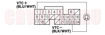
- Disconnect the ECM/PCM connector B (24P).
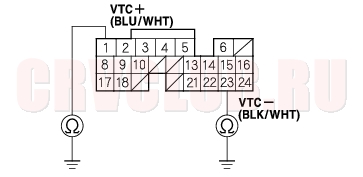
- Measure resistance between ECM/PCM connector terminal B1 and B23.
Is there 6.75 - 8.25
?
Yes : Go to step 12.
No : Go to step 8.
- Disconnect the VTC oil control solenoid valve 2P connector.
- Measure resistance between VTC oil control solenoid valve 2P terminal No. 1 and No. 2.
Is there 6.75 - 8.25
Yes : Go to step 10.
No : Replace the VTC oil control solenoid valve (see page 11-137).
- Connect VTC oil control solenoid valve 2P connector terminals No. 1 and No. 2 to body ground with a jumper wire individually.
11-125
Is there continuity?
Yes : Go to step 12.
No : Repair open in the wire between the ECM/PCM (B1, B23) and the VTC oil control solenoid valve.
Is there continuity?
Yes : Go to step 13.
No : Substitute a known-good ECM/PCM and recheck (see page 11-5). If the symptom/indication goes away with a known-good ECM/PCM, replace the original ECM/PCM.
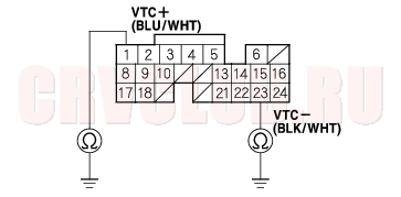
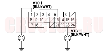
- Disconnect the VTC oil control solenoid valve 2P connector.
- Check for continuity between ECM/PCM connector terminals B1 and B23 and body ground individually.
Is there continuity?
Yes : Repair short in the wire between the ECM/PCM (B1, B23) and the VTC oil control solenoid valve.
No : Replace the VTC oil control solenoid valve (see page 11-137).
DTC Troubleshooting (cont'd)11-126
DTC P0011 (56-2): VTC System Malfunction
- Reset the ECM/PCM (see page 11-4) .
- Start the engine. Hold the engine at 3,000 rpm (min-1) with no load (in Park or neutral) until the radiator fan comes on.
- Test-drive at a steady speed between 30 - 60 km/h (20 - 40 mph) for 10 minutes.
- Check for Temporary DTC with the scan tool.
Is Temporary DTC P0011 indicated?
Yes : Go to step 5.
No : Intermittent failure, system is OK at this time. Check for poor connections or loose wires at the VTC oil control solenoid valve and at the ECM/PCM.
Is the low oil pressure light on?
Yes : Check the oil pressure (see page 08-4).
No : Go to step 6.
- Turn the ignition switch OFF.
- Remove the auto-tensioner (see page 04-31) .
- Remove the VTC strainer. Check the VTC strainer for clogging.
Is the strainer OK?
Yes : Go to step 9.
No : Clean the VTC strainer, then replace the engine oil filter and the engine oil.
- Check the VTC oil control solenoid valve (see page 11-137) .
Is the VTC oil control solenoid valve OK?
Yes : Go to step 10.
No : Clean the ports of the VTC oil control solenoid valve, or replace the VTC oil control solenoid valve.
- Install the VTC oil control solenoid valve.
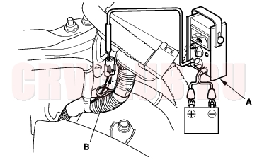
- Connect a tachometer (A) to the test tachometer connector (B).
- Start the engine. Hold the engine at 700 - 1,000 rpm (min-1).
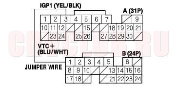
- Connect the ECM/PCM connector terminal B23 to body ground with a jumper wire.
11-127
- Connect the ECM/PCM connector terminal A3 and B1 with a jumper wire for below 1 minute.
- NOTE: Do not jump for above 1 minute.
Did the engine stall or run rough?
Yes : Test-drive at a steady speed between 30 - 60 km/h (19 - 37 mph) for 10 minutes. If temporary DTC P0011 is indicated, substitute a known-good ECM/PCM and recheck (see page 11-5), replace the original ECM/PCM.
No : Go to step 15.
- Check the VTC actuator (see page 06-8) .
Is the VTC actuator OK?
Yes : Remove the auto-tensioner (see page 04-31) and replace the VTC oil filter. Substitute a known-good ECM/PCM and recheck (see page 11-5). If symptom/indication goes away, replace the original ECM/PCM.
No : Replace the VTC actuator.
DTC Troubleshooting (cont'd)11-128
DTC P0340 (57-1): CMP Sensor No Signal
DTC P0344 (57-2): CMP Sensor Intermittent Interruption
- Reset the ECM/PCM (see page 11-4) .
- Start the engine.
Is DTC P0340 and/or P0344 indicated?
Yes : Go to step 3.
No : Intermittent failure, system is OK at this time. Check for poor connections or loose wires at the CMP sensor and at the ECM/PCM.
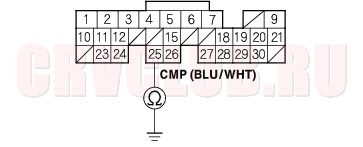
- Turn the ignition switch OFF.
- Disconnect the CMP sensor 3P connector.
- Turn the ignition switch ON (II).
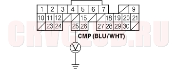
- Measure voltage between CMP sensor 3P connector terminal No. 3 and body ground.
Is there battery voltage?
Yes : Go to step 7.
No : Check the No. 4 ACG (10A) fuse in the under-dash fuse/relay box. If the fuse is OK, repair open in the wire between the CMP sensor and No. 4 ACG (10A) fuse.
Is there about 5 V?
Yes : Go to step 8.
No : Go to step 10.
Is there battery voltage?
Yes : Go to step 9.
No : Repair open in the wire between the CMP sensor and G101.
Is DTC P0340 and/or P0344 indicated?
Yes : Substitute a known-good ECM/PCM and recheck (see page 11-5). If symptom/indication goes away, replace the original ECM/PCM.
No : Replace the original CMP sensor.
11-129
Is there about 5 V?
Yes : Repair open in the wire between the ECM/PCM (A25) and CMP sensor.
No : Go to step 11.
- Turn the ignition switch OFF.
- Disconnect the negative cable from the battery.
- Disconnect ECM/PCM connector A (31P).
- Check for continuity between ECM/PCM connector terminal A25 and body ground.
Is there continuity?
Yes : Repair short in the wire between the ECM/PCM (A25) and the CMP sensor.
No : Substitute a known-good ECM/PCM and recheck (see page 11-5). If symptom/indication goes away, replace the original ECM/PCM.
DTC P0341 (57-3): VTC Phase Gap
- Reset the ECM/PCM (see page 11-4) .
- Start the engine.
Is DTC P0341 indicated?
Yes : Go to step 3.
No : Intermittent failure, system is OK at this time. Check for poor connections or loose wires at the CMP sensor and at the ECM/PCM.
- Check the VTC oil control solenoid valve (see page 11-137) .
Is the VTC oil control solenoid valve OK?
Yes : Go to step 4.
No : Clean the VTC oil control solenoid valve, or replace the VTC oil control solenoid valve.
- Remove the head cover and check the cam chain (see page 06-15) .
Is the cam chain OK?
Yes : Go to step 5.
No : Repair or replace the cam chain.
- Check the slack in the cam chain (see page 06-22) .
Is the cam chain OK?
Yes : Go to step 6.
No : Repair or replace the cam chain.
- Check the VTC actuator (see page 06-8) .
Is the VTC actuator OK?
Yes : Substitute a known-good ECM/PCM and recheck (see page 11-5). If symptom/indication goes away, replace the original ECM/PCM.
No : Replace the VTC actuator.
DTC Troubleshooting (cont'd)11-130
DTC P1253 (21-1): VTEC System Malfunction
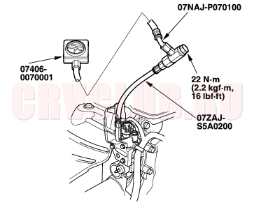
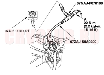
Special Tools Required
Oil Pressure gauge attachment 07NAJ-P070100 Low pressure gauge 07406-0070001 Hose oil pressure 07ZAJ-S5A0200
- Reset the ECM/PCM (see page 11-4) .
- Check the engine oil level, and refill if necessary. Check for external damage to the oil pan.
- Start the engine. Hold the engine at 3,000 rpm (min-1) with no load (in Park or neutral) unit the radiator fan comes on.
- Road test the vehicle:
Accelerate in MT, A/T: 2nd gear to an engine speed over 4,000 rpm (min-1). Hold that engine speed for at least 2 seconds. If DTC P1253 is not repeated during the first road test, repeat this test 2 more times.
Is DTC P1253 indicated?
Yes : Go to step 5.
No : Intermittent failure, system is OK at this time. Check the oil consumption if oil was added in step 2. Check for poor connections or loose wires at the VTEC solenoid valve and at the ECM/PCM.
- Turn the ignition switch OFF.
- Turn the ignition switch OFF.
- Disconnect the VTEC solenoid valve 2P connector.
- Check for resistance between VTEC solenoid valve 2P connector terminals No. 1 and No. 2.
Is there 14 - 30
Yes : Go to step 9.
No : Replace the VTEC solenoid valve.
- Disconnect the negative cable from the battery.
- Disconnect ECM/PCM connector B (24P).
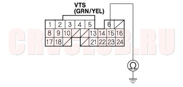
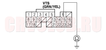
- Check for continuity between ECM/PCM connector terminal B15 and body ground.
Is there continuity?
Yes : Repair short in the wire between the VTEC solenoid valve and the ECM/PCM (B15).
No : Go to step 12.
11-131
Is there continuity?
Yes : Go to step 14.
No : Repair open in the wire between the VTEC solenoid valve and the ECM/PCM (B15).
- Install the special tools as shown.
- Reconnect ECM/PCM connector B (24P) and the VTEC solenoid valve connector.
- Connect a tachometer.
- Reconnect the negative cable to the battery.
- Start the engine. Hold the engine at 3,000 rpm (min-1) with no load (in Park or neutral) unit the radiator fan comes on.
- Check oil pressure at engine speeds of 1,000 and 2,000 rpm (min-1). Keep measuring time as short as possible because the engine is running with no load (less than 1 minute).
Is pressure below 49 kPa (0.5 kgf/cm2, 7 psi)?
Yes : Go to step 20.
No : Inspect the VTEC solenoid valve (see page 11-138).
DTC Troubleshooting (cont'd)11-132
- Turn the ignition switch OFF.
- Disconnect the VTEC solenoid valve 2P connector.
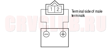
- Attach the battery positive terminal to VTEC solenoid valve 2P connector terminal No. 2.
- Start the engine, then connect the battery negative to terminal No. 1 and check oil pressure at an engine speed of 3,000 rpm (min-1).
Is pressure above 390 kPa (4.0 kgf/cm2, 57 psi)?
Yes : Substitute a known-good ECM/PCM and recheck (see page 11-5). If the symptom/indication goes away, replace the original ECM/PCM.
No : Inspect the VTEC solenoid valve (see page 11-138).
11-133
DTC P1259 (22-4): VTEC System Malfunction
Special Tools Required
Oil Pressure gauge attachment 07NAJ-P070100 Low pressure gauge 07406-0070001 Hose oil pressure 07ZAJ-S5A0200
- Reset the ECM/PCM (see page 11-4) .
- Check the engine oil level, and refill if necessary.
- Start the engine. Hold the engine at 3,000 rpm (min-1) with no load (in Park or neutral) until the radiator fan comes on.
- Road test the vehicle:
Accelerate in 1st gear to an engine speed over 4,000 rpm (min-1). Hold that engine speed for at least 2 seconds. If DTC P1259 is not repeated during the first road test, repeat this test 2 more times.
Is DTC P1259 indicated?
Yes : Go to step 5.
No : Intermittent failure, system is OK at this time. Check for poor connections or loose wires at the VTEC solenoid valve and at the ECM/PCM.
- Turn the ignition switch OFF.
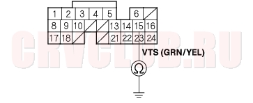
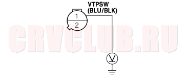
- Disconnect the VTEC oil pressure switch 2P connector.
- Check for continuity on VTEC oil pressure switch between the VTEC oil pressure switch 2P connector terminals No. 1 and No. 2.
Is there continuity?
Yes : Go to step 8.
No : Replace the VTEC oil pressure switch.
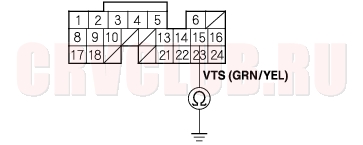
- Turn the ignition switch ON (II).
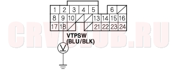
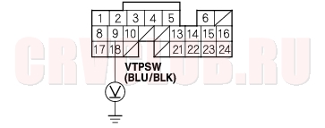
- Measure voltage between VTEC oil pressure switch 2P connector terminal No. 1 and body ground.
Is there battery voltage?
Yes : Go to step 15.
No : Go to step 10.
DTC Troubleshooting (cont'd)11-134
Is there battery voltage?
Yes : Repair open in the wire between the VTEC oil pressure switch and the ECM/PCM (B9).
No : Go to step 11.
- Turn the ignition switch OFF.
- Disconnect the negative cable from the battery.
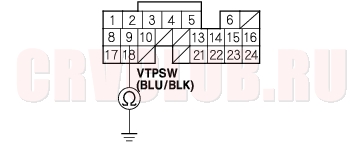
- Disconnect ECM/PCM connector B (24P).
- Check for continuity between ECM/PCM connector terminal B9 and body ground.
Is there continuity?
Yes : Repair short in the wire between the VTEC oil pressure switch and the ECM/PCM (B9).
No : Substitute a known-good ECM/PCM and recheck (see page 11-5). If symptom/indication goes away, replace the original ECM/PCM.
Is there battery voltage?
Yes : Go to step 16.
No : Repair open in the wire between the VTEC oil pressure switch and G101.
- Turn the ignition switch OFF.
- Disconnect the VTEC solenoid valve 1P connector.
- Check for resistance between VTEC solenoid valve 2P connector terminals No. 1 and No. 2.
Is there 14 - 30
Yes : Go to step 19.
No : Replace the VTEC solenoid valve.
11-135
- Remove the VTEC oil pressure switch (A) and install the special tools as shown, then reinstall the VTEC oil pressure switch.
- Reconnect the VTEC solenoid valve 2P connector and VTEC oil pressure switch 2P connector.
- Connect a tachometer.
- Start the engine. Hold the engine at 3,000 rpm (min-1) with no load (in Park or neutral) until the radiator fan comes on.
- Check oil pressure at engine speeds of 1,000 and 2,000 rpm (min-1). Keep measuring time as short as possible because the engine is running with no load (less than 1 minute).
Is pressure below 49 kPa (0.5 kgf/cm2, 7 psi)?
Yes : Go to step 24.
No : Inspect the VTEC solenoid valve (see page 11-138).
- Turn the ignition switch OFF.
- Disconnect the VTEC solenoid valve 2P connector.
- Attach the battery positive terminal to the VTEC solenoid valve 2P connector terminal No. 2.
- Start the engine, then connect the battery negative to terminal No. 1 and check oil pressure at an engine speed of 3,000 rpm (min-1).
Is pressure above 390 kPa (4.0 kgf/cm2, 57 psi)?
Yes : Go to step 28.
No : Inspect the VTEC solenoid valve (see page 11-138).
- With the battery terminal still connected to the VTEC solenoid valve, measure voltage between ECM/PCM connector terminal B9 and body ground.
Is there battery voltage above 4,000 rpm (min-1)?
Yes : Go to step 29.
No : Replace the VTEC oil pressure switch.
- Turn the ignition switch OFF.
- Disconnect the battery terminal from the VTEC solenoid valve terminal.
DTC Troubleshooting (cont'd)11-136
- Reconnect the negative cable to the battery.
- Disconnect ECM/PCM connector B (24P).
- Check for continuity between ECM/PCM connector terminal B15 and body ground.
Is there continuity?
Yes : Repair short in the wire between the VTEC solenoid valve and the ECM/PCM (B15).
No : Go to step 34.
Is there continuity?
Yes : Substitute a known-good ECM/PCM and recheck (see page 11-5). If symptom/indication goes away, replace the original ECM/PCM.
No : Repair short in the wire between the VTEC solenoid valve and the ECM/PCM (B15).
VTC Oil Control Solenoid Valve Test11-137
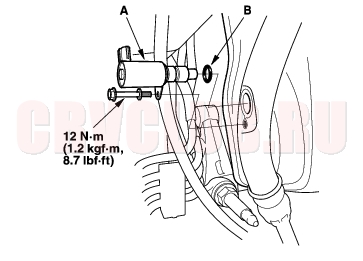
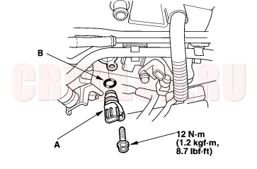
- Remove the VTC oil control solenoid valve (A).
- NOTE: Install the part in the reverse order of removal with a new O-ring (B), then check these items:
- Clean and dry the VTC oil control solenoid valve mating surface.
- Coat O-ring with engine oil.
- Do not install the VTC oil control solenoid valve while wearing fibrous gloves.
- Be careful not to contaminate the cylinder head opening.
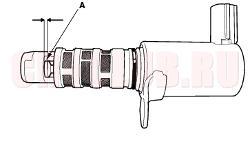
- Check the VTC oil control solenoid valve filter for clogging. If it is clogged, replace the VTC oil control solenoid valve.
- Check the clearance between the port (advance side) and the valve. Clearance (A) should be above 2.8 mm (1/8 in.).
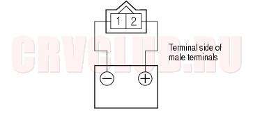
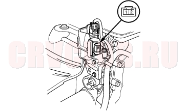
- Connect the battery positive terminal to the VTC oil control solenoid valve 2P connector terminal No. 2.
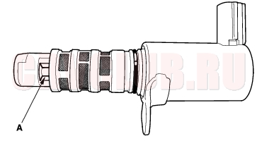
- Connect the battery negative terminal to the VTC oil control solenoid valve 2P connector terminal No. 1, then make sure the valve (A) opens fully.
CMP Sensor Replacement11-138
- Remove the air cleaner (see page 11-182) .
- Disconnect the CMP sensor 3P connector.
- Remove the CMP sensor (A).
- Install the part in the reverse order of removal with a new O-ring (B).
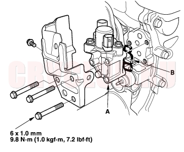
VTEC Solenoid Valve Removal/Inspection11-138
- Disconnect the VTEC solenoid valve 2P connector.
- KG, KS, KE, KR, KU (Hong Kong) models: Disconnect the VTEC oil pressure switch 2P connector.
- Measure resistance between the VTEC solenoid valve connector terminals No. 1 and No. 2.
Resistance: 14 - 30
*: The illustration shows KG, KS, KE, KR, KU (Hong Kong) models.
- If the resistance is within specifications, remove the VTEC solenoid valve assembly (A) from the cylinder head, and check the VTEC solenoid valve filter (B) for clogging. If it is clogged, replace the solenoid valve filter, the engine oil filter, and the engine oil.
*: The illustration shows KG, KS, KE, KR, KU (Hong Kong) models
|
Fuel and Emissions11-1
VTEC/VTC11-123 |