PGM-FI System11-59
|
Fuel and Emissions11-1
PGM-FI System11-59 |
PGM-FI System11-59
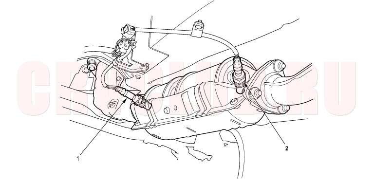
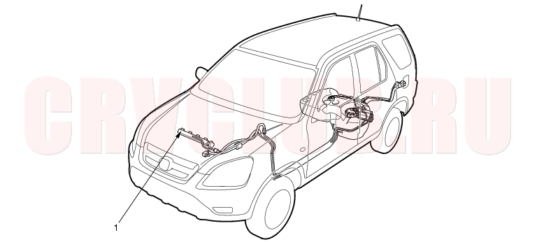
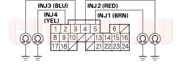
Component Location Index
*: The illustration shows LHD model
Troubleshooting, page 11-100 ; Replacement, page 11-120 Troubleshooting, page 11-97 Troubleshooting, page 11-64 ; Replacement, page 11-121 Troubleshooting, page 11-66 ; Replacement, page 11-120 Troubleshooting, page 11-62 Troubleshooting, page 11-68 Troubleshooting, page 11-87 ; Replacement, page 11-121 Troubleshooting, page 11-88 ; Replacement, page 11-119
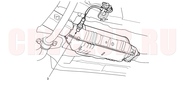
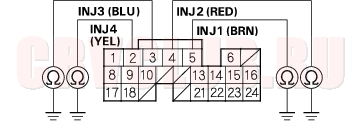
Component Location Index (cont'd)11-60
KG, KS, KE, KR, KU, KZ, FO, KQ models:
KN, KM, KY, MA, PH, IN, KK models:
Troubleshooting, page 11-71 ; Replacement, page 11-119 Troubleshooting, page 11-76 ; Replacement, page 11-122 Troubleshooting, page 11-71 ; Replacement, page 11-119
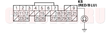
11-61
*: The illustration shows KG, KS, KE, KR models.
*: The illustration shows LHD model
Test, page 11-116 ; Replacement, page 11-117 General Troubleshooting Information, page 11-3 ; Troubleshooting, page 11-101 Troubleshooting, page 11-102 Troubleshooting, page 11-94 General Troubleshooting Information, page 11-3
DTC Troubleshooting11-62
DTC P0107(3-1): MAP Sensor Circuit Low Voltage
Is about 101 kPa (760 mmHg, 30 in.Hg) or 2.9 V indicated?
Yes : Intermittent failure, system is OK at this time. Check for poor connections or loose wires at the MAP sensor and at the ECM/PCM.

No : Go to step 3.
- Turn the ignition switch OFF.
- Disconnect the MAP sensor 3P connector.
- Turn the ignition switch ON (II).
- Measure voltage between MAP sensor 3P connector terminals No. 1 and No. 3.
Is there about 5 V?
Yes : Go to step 8.
No : Go to step 7.
Is there about 5 V?
Yes : Repair open in the wire between ECM/PCM (A21) and the MAP sensor.
No : Substitute a known-good ECM/PCM and recheck (see page 11-5). If the symptom/indication goes away, replace the original ECM/PCM.
Is 2 kPa (15 mmHg, 0.6 in.Hg) or less or 0 V indicated?
Yes : Go to step 9.
No : Replace the MAP sensor.
- Disconnect the negative cable from the battery.
- Turn the ignition switch OFF.
- Disconnect ECM/PCM connector A (31P).
- Check for continuity between MAP sensor connector terminal No. 2 and body ground.
Is there continuity?
Yes : Repair short in the wire between the ECM/PCM (A19) and the MAP sensor.
No : Substitute a known-good ECM/PCM and recheck (see page 11-5) If the symptom/indication goes away, replace the original ECM/PCM.
11-63
DTC P0108 (3-2): MAP Sensor Circuit High Voltage
- Start the engine. Hold the engine at 3,000 rpm (min-1) with no load (in Park or neutral) until the radiator fan comes on, then let it idle with no load.
- Check the MAP with the scan tool.
Is about 101 kPa (760 mmHg, 30 in.Hg) or higher, or about 2.9 V or higher indicated?
Yes : Go to step 3.
No : Intermittent failure, system is OK at this time. Check for poor connections or loose wires at the MAP sensor and at the ECM/PCM.
- Turn the ignition switch OFF.
- Disconnect the MAP sensor 3P connector.
- Connect MAP sensor 3P connector terminals No. 2 and No. 3 with a jumper wire.
Is about 101 kPa (760 mmHg, 30 in.Hg) or higher, or about 2.9 V or higher indicated?
Yes : Go to step 8.
No : Replace the MAP sensor.
Is there about 5 V?
Yes : Go to step 10.
No : Repair open in the wire between the ECM/PCM (A11) and the MAP sensor.
Is about 101 kPa (760 mmHg, 30 in.Hg) or higher, or about 2.9 V or higher indicated?
Yes : Substitute a known-good ECM/PCM and recheck (see page 11-5). If the symptom/indication goes away, replace the original ECM/PCM.
No : Repair open in the wire between the ECM/PCM (A19) and the MAP sensor.
DTC Troubleshooting (cont'd)11-64
DTC P0112 (10-1): IAT Sensor Circuit Low Voltage
Is 150°C (302°F) or higher (or H-Limit in Honda mode of PGM Tester) or 0 V indicated?
Yes : Go to step 3.
No : Go to step 9.
Is 150°C (302°F) or higher (or H-Limit in Honda mode of PGM Tester) or 0 V indicated?
Yes : Go to step 5.
No : Replace the IAT sensor.
- Turn the ignition switch OFF.
- Disconnect the negative cable from the battery.
- Disconnect ECM/PCM connector B (24P).
- Check for continuity between IAT sensor 2P connector terminal No. 2 and body ground.
Is there continuity?
Yes : Repair short in the wire between the ECM/PCM (B17) and the IAT sensor.
No : Substitute a known-good ECM/PCM and recheck (see page 11-5). If the symptom/indication goes away, replace the original ECM/PCM.
- Check the temperature reading on the scan tool.
Be aware that if the engine is warm, the reading will be higher than ambient temperature. If the engine is cold, the IAT and ECT will have the same value.
Is the correct ambient temperature indicated?
Yes : Intermittent failure, system is OK at this time. Check for poor connections or loose wires at the IAT sensor and at the ECM/PCM.
No : Replace the IAT sensor.
11-65
DTC P0113 (10-2): IAT Sensor Circuit High Voltage
Is -20°C (-4°F) or less (or L-Limit in Honda mode of PGM Tester) or 5 V indicated?
Yes : Go to step 3.
No : Intermitent failure, system is OK at this time. Check for poor connections or loose wires at the IAT sensor and at the ECM/PCM.
- Turn the ignition switch OFF.
- Disconnect the IAT sensor 2P connector.
- Connect IAT sensor 2P connector terminals No. 1 and No. 2 with a jumper wire.
Is -20°C (-4°F) or less (or L-Limit in Honda mode of PGM Tester) or 5 V indicated?
Yes : Go to step 8.
No : Replace the IAT sensor.
- Turn the ignition switch OFF.
- Remove the jumper wire.
- Connect ECM/PCM connector terminals A10 and B17 with a jumper wire.
Is -20°C (-4°F) or less (or L-Limit in Honda mode of PGM Tester) or 5 V indicated?
Yes : Substitute a known-good ECM/PCM and recheck (see page 11-5). If the symptom/indication goes away, replace the original ECM/PCM.
No : Repair open in the wire between the ECM/PCM (A10, B17) and the IAT sensor.
DTC Troubleshooting (cont'd)11-66
DTC P0117 (6-1): ECT Sensor Circuit Low Voltage
Is 150°C (302°F) or higher (or H-Limit in Honda mode of PGM Tester) or 0 V indicated?
Yes : Go to step 3.
No : Intermittent failure, system is OK at this time. Check for poor connections or loose wires at the ECT sensor and at the ECM/PCM.
Is 150°C (302°F) or higher (or H-Limit in Honda mode of PGM Tester) or 0 V indicated?
Yes : Go to step 5.
No : Replace the ECT sensor.
- Turn the ignition switch OFF.
- Disconnect the negative cable from the battery.
- Disconnect ECM/PCM connector B (24P).
- Check for continuity between ECT sensor 2P connector terminal No. 1 and body ground.
Is there continuity?
Yes : Repair short in the wire between the ECM/PCM (B8) and the ECT sensor.
No : Substitute a known-good ECM/PCM and recheck (see page 11-5). If the symptom/indication goes away, replace the original ECM/PCM.
11-67
DTC P0118 (6-2): ECT Sensor Circuit High Voltage
Is -20°C (-4°F) or less (or L-Limit in Honda mode of PGM Tester) or 5 V indicated?
Yes : Go to step 3.
No : Intermittent failure, system is OK at this time. Check for poor connections or loose wires at the ECT sensor and at the ECM/PCM.
- Turn the ignition switch OFF.
- Disconnect the ECT sensor 2P connector.
- Connect ECT sensor 2P connector terminals No. 1 and No. 2 with a jumper wire.
Is -20°C (-4°F) or less (or L-Limit in Honda mode of PGM Tester) or 5 V indicated?
Yes : Go to step 8.
No : Replace the ECT sensor.
- Turn the ignition switch OFF.
- Remove the jumper wire.
- Connect ECM/PCM connector terminals A10 and B8 with a jumper wire.
Is -20°C (-4°F) or less (or L-Limit in Honda mode of PGM Tester) or 5 V indicated?
Yes : Substitute a known-good ECM/PCM and recheck (see page 11-5). If the symptom/indication goes away, replace the original ECM/PCM.
No : Repair open in the wire between the ECM/PCM (A10, B8) and the ECT sensor.
DTC Troubleshooting (cont'd)11-68
DTC P0122 (7-1): TP Sensor Circuit Low Voltage
Is there about 10% or 0.5 V when the throttle is fully closed and about 90% or 4.5 V when the throttle is fully opened?
Yes : Intermittent failure, system is OK at this time. Check for poor connections or loose wires at the TP sensor and at the ECM/PCM.
No : Go to step 3.
- Turn the ignition switch OFF.
- Disconnect the TP sensor 3P connector.
- Turn the ignition switch ON (II).
- Measure voltage between TP sensor 3P connector terminals No. 1 and No. 3.
Is there about 5 V?
Yes : Go to step 7.
No : Go to step 15.
- Turn the ignition switch OFF.
- At the sensor side, measure resistance between TP sensor 3P connector terminals No. 1 and No. 3 with the throttle fully closed.
Trerminal side of male terminals
Is there about 0.5 - 0.9 k
?
Yes : Go to step 9.
No : Replace the throttle body.
- Measure resistance between TP sensor 3P connector terminals No. 1 and No. 2 with the throttle fully closed.
Terminal side of male terminals
Is there about 4.5 k
Yes : Go to step 10.
No : Replace the throttle body (the TP sensor is not available separately).
11-69
- At the wire harness side, check for continuity between TP sensor 3P connector terminal No. 2 and body ground.
Is there continuity?
Yes : Repair short in the wire between the ECM/PCM (A15) and the TP sensor.
No : Go to step 13.
- At the wire harness side, check for continuity between TP sensor 3P connector terminals No. 2 and body ground.
Is there continuity?
Yes : Substitute a known-good ECM/PCM and recheck (see page 11-5). If the symptom/indication goes away, replace the original ECM/PCM.
No : Repair open in the wire between the ECM/PCM (A15) and the TP sensor.
Is there about 5 V?
Yes : Repair open in the wire between the ECM/PCM (A20) and the TP sensor.
No : Substitute a known-good ECM/PCM and recheck (see page 11-5). If the symptom/indication goes away, replace the original ECM/PCM.
DTC Troubleshooting (cont'd)11-70
DTC P0123 (7-2): TP Sensor Circuit High Voltage
Is there about 10% or 0.5 V when the throttle is fully closed and about 90% or 4.5 V when the throttle is fully opened?
Yes : Intermittent failure, system is OK at this time. Check for poor connections or loose wires at the TP sensor and at the ECM/PCM.
No : Go to step 3.
- Turn the ignition switch OFF.
- Disconnect the TP sensor 3P connector.
- Turn the ignition switch ON (II).
- At the wire harness side, measure voltage between TP sensor 3P connector terminals No. 1 and No. 3.
Is there about 5 V?
Yes : Replace the throttle body (the TP sensor is not available separately).
No : Go to step 7.
Is there about 5 V?
Yes : Repair open in the wire between the ECM/PCM (A10) and the TP sensor.
No : Substitute a known-good ECM/PCM and recheck (see page 11-5). If symptom/indication goes away, replace the original ECM/PCM.
11-71
DTC P0131 (1-1): Primary HO2S (Sensor 1) Circuit Low Voltage
- Reset the ECM/PCM (see page 11-4)
- Start the engine. Hold the engine at 3,000 rpm (min-1) with no load (in Park or neutral) until the radiator fan comes on.
- Check the primary HO2S (Sensor 1) output voltage with the scan tool during acceleration using wide open throttle.
Does the voltage stay at 0.5 V or less?
Yes : Go to step 4.
No : Intermittent failure, system is OK at this time. Check for poor connections or loose wires at the primary HO2S (Sensor 1) and at the ECM/PCM.
- Check the fuel pressure (see page 11-154) .
Is it normal?
Yes : Go to step 5.
No : Repair the fuel supply system.
- Turn the ignition switch OFF.
- Disconnect the primary HO2S (Sensor 1) 4P connector.
- Turn the ignition switch ON (II).
- Check the primary HO2S (Sensor 1) output voltage with the scan tool.
Does it stay at 0.5 V or less?
Yes : Go to step 9.
No : Replace the primary HO2S (Sensor 1).
- Turn the ignition switch OFF.
- Disconnect the negative cable from the battery.
- Disconnect ECM/PCM connector A (31P).
- Check for continuity between primary HO2S (Sensor 1) 4P connector terminal No. 1 and body ground.
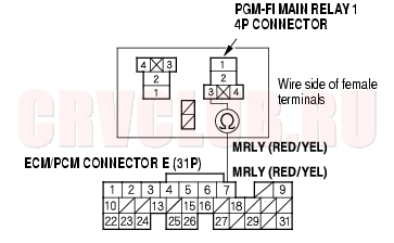
PRIMARY HO2S (SENSOR 1) 4P CONNECTOR
Is there continuity?
Yes : Repair short in the wire between the ECM/PCM (A6) and the primary HO2S (Sensor 1).
No : Substitute a known-good ECM/PCM and recheck (see page 11-5). If symptom/indication goes away, replace the original ECM/PCM.
DTC Troubleshooting (cont'd)11-72
DTC P0132 (1-2): Primary HO2S (Sensor 1) Circuit High Voltage
- Reset the ECM/PCM (see page 11-4) .
- Start the engine. Hold the engine at 3,000 rpm (min-1) with no load (in Park or neutral) until the radiator fan comes on.
- Check the primary HO2S (Sensor 1) output voltage with the scan tool.
Does the voltage stay at 0.9 V or more?
Yes : Go to step 4.
No : Intermittent failure, system is OK at this time. Check for poor connections or loose wires at the primary HO2S (Sensor 1) and at the ECM/PCM.
- Turn the ignition switch OFF.
- Disconnect the primary HO2S (Sensor 1) 4P connector.
- Connect primary HO2S (Sensor 1) 4P connector terminals No. 1 and No. 2 with a jumper wire.
PRIMARY HO2S (SENSOR 1) 4P CONNECTOR
- Turn the ignition switch ON (II).
- Check the primary HO2S (Sensor 1) output voltage with the scan tool.
Is there 0.9 V or more?
Yes : Go to step 9.
No : Replace the primary HO2S (Sensor 1).
- Turn the ignition switch ON (II).
- Check the primary HO2S (Sensor 1) output voltage with the scan tool.
Is there 0.9 V or more?
Yes : Substitute a known-good ECM/PCM and recheck (see page 11-5). If symptom/indication goes away, replace the original ECM/PCM.
No : Repair open in the wire between the ECM/PCM (A6, E4) and the primary HO2S (Sensor 1).
11-73
DTC P0133 (61-1): Primary HO2S (Sensor 1) Slow Response
NOTE: If DTC P0131, P0132 and/or P0135 are stored at the same time as DTC P0133, troubleshoot those DTCs first, then recheck for DTC P0133.
- Reset the ECM/PCM (see page 11-4) .
- Start the engine. Hold the engine at 3,000 rpm (min-1) with no load (in Park or neutral) until the radiator fan comes on.
- Test-drive under the following conditions:
- 89 km/h (55 mph) steady speed
- A/T in D position (M/T in 5th gear)
- Until readiness code or Temporary DTC P0133 comes on
- Check for a Temporary DTC with the scan tool.
Is Temporary DTC P0133 indicated?
Yes : Replace the primary HO2S (Sensor 1).
No : Intermittent failure, system is OK at this time. Check for poor connections or loose wires at the primary HO2S (Sensor 1) and the ECM/PCM.
DTC Troubleshooting (cont'd)11-74
DTC P0135 (41-2): Primary HO2S (Sensor 1) Heater Circuit Malfunction
- Reset the ECM/PCM (see page 11-4) .
- Start the engine.
Is DTC P0135 indicated?
Yes : Go to step 3.
No : Intermittent failure, system is OK at this time. Check for poor connections or loose wires at the primary HO2S (Sensor 1) and at the ECM/PCM.
- Turn the ignition switch OFF.
- Disconnect the primary HO2S (Sensor 1) 4P connector.
- Turn the ignition switch ON (II).
- Measure voltage between primary HO2S
(Sensor 1) 4P connector terminal No. 3 and body ground.
PRIMARY HO2S (SENSOR 1) 4P CONNECTOR
Is there battery voltage?
Yes : Go to step 8.
No : Go to step 7.
PRIMARY HO2S (SENSOR 1) 4P CONNECTOR
Is there continuity?
Yes : Repair short in the wire between the primary HO2S (Sensor 1) and the No. 4 ACG (10A) fuse.
No : Check the No. 4 ACG (10A) fuse in the under-dash fuse/relay box. If the fuse is OK, repair open in the wire between the primary HO2S (Sensor 1) and the No. 4 ACG (10A) fuse.
- Turn the ignition switch OFF.
- Reconnect the primary HO2S (Sensor 1) 4P connector.
- Disconnect the negative cable from the battery.
- Disconnect ECM/PCM connector A (31P).
- Reconnect the negative cable to the battery.
- Turn the ignition switch ON (II).
11-75
Is there battery voltage?
Yes : Go to step 15.
No : Repair open in the wire between ECM/PCM (A1) and primary HO2S (Sensor 1).
- Turn the ignition switch OFF.
- Disconnect the primary HO2S (Sensor 1) 4P connector.
- Check for continuity between body ground and ECM/PCM connector terminal A1.
Is there continuity?
Yes : Repair short in the wire between the ECM/PCM (A1) and primary HO2S (Sensor 1).
No : Go to step 18.
Is DTC P0135 indicated?
Yes : Substitute a known-good ECM/PCM and recheck (see page 11-5). If the symptom/indication goes away with a known-good ECM/PCM, replace the original ECM/PCM.
No : Replace the primary HO2S (Sensor 1).
DTC Troubleshooting (cont'd)11-76
DTC P0137 (63-1): Secondary HO2S (Sensor 2) Circuit Low Voltage
- Reset the ECM/PCM (see page 11-4) .
- Start the engine. Hold the engine at 3,000 rpm (min-1) with no load (in Park or neutral) until the radiator fan comes on.
- Check the secondary HO2S (Sensor 2) output voltage at 3,000 rpm (min-1) with the scan tool.
Does the voltage stay at 0.3 V or less?
Yes : Go to step 4.
No : Intermittent failure, system is OK at this time. Check for poor connections or loose wires at the secondary HO2S (Sensor 2) and at the ECM/PCM.
- Turn the ignition switch OFF.
- Disconnect the secondary HO2S (Sensor 2) 4P connector.
- Turn the ignition switch ON (II).
- Check the secondary HO2S (Sensor 2) output voltage with the scan tool.
Does the voltage stay at 0.3 V or less?
Yes : Go to step 8.
No : Replace the secondary HO2S (Sensor 2).
- Turn the ignition switch OFF.
- Disconnect the negative cable from the battery.
- Disconnect ECM/PCM connector E (31P).
- Check for continuity between secondary HO2S (Sensor 2) 4P connector terminal No. 2 and body ground.
SECONDARY HO2S (SENSOR 2) 4P CONNECTOR
Terminal side of male terminals
Is there continuity?
Yes : Repair short in the wire between the ECM/PCM (E2) and the secondary HO2S
(Sensor 2).
No : Substitute a known-good ECM/PCM and recheck (see page 11-5). If symptom/indication goes away, replace the original ECM/PCM.
11-77
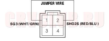
DTC P0138 (63-2): Secondary HO2S (Sensor 2) Circuit High Voltage
- Reset the ECM/PCM (see page 11-4) .
- Start the engine. Hold the engine at 3,000 rpm (min-1) with no load (in Park or neutral) until the radiator fan comes on.
- Check the secondary HO2S (Sensor 2) output voltage at 3,000 rpm (min-1) with the scan tool.
Does the voltage stay at 1.0 V or more?
Yes : Go to step 4.
No : Intermittent failure, system is OK at this time. Check for poor connections or loose wires at the secondary HO2S (Sensor 2) and the at ECM/PCM.
- Turn the ignition switch OFF.
- Disconnect the secondary HO2S (Sensor 2) 6P connector.
- Connect secondary HO2S (Sensor 2) 6P connector terminals No. 1 and No. 2 with a jumper wire.
SECONDARY HO2S (SENSOR 2) 4P CONNECTOR
Terminal side of male terminals
- Turn the ignition switch ON (II).
- Check the secondary HO2S (Sensor 2) output voltage with the scan tool.
Is there 1.0 V or more?
Yes : Go to step 9.
No : Replace the secondary HO2S (Sensor 2).
- Turn the ignition switch ON (II).
- Check the secondary HO2S (Sensor 2) output voltage with the scan tool.
Is there 1.0 V or more?
Yes : Substitute a known-good ECM/PCM and recheck (see page 11-5). If symptom/indication goes away, replace the original ECM/PCM.
No : Repair open in the wire between the ECM/PCM (E2, E4) and the secondary HO2S (Sensor 2).
DTC Troubleshooting (cont'd)11-78
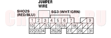
DTC P0141 (65-2): Secondary HO2S (Sensor 2) Heater Circuit Malfunction
- Reset the ECM/PCM (see page 11-4) .
- Start the engine.
Is DTC P0141 indicated?
Yes : Go to step 3.
No : Intermittent failure, system is OK at this time. Check for poor connections or loose wires at the secondary HO2S (Sensor 2) and at the ECM/PCM.
- Turn the ignition switch OFF.
- Disconnect the secondary HO2S (Sensor 2) 4P connector.
- At the secondary HO2S (Sensor 2) side, measure resistance between the HO2S 4P connector terminals No. 3 and No. 4.
SECONDARY HO2S (SENSOR 2) 4P CONNECTOR
Is there about 3.3
Yes : Go to step 6.
No : Replace the secondary HO2S (Sensor 2).
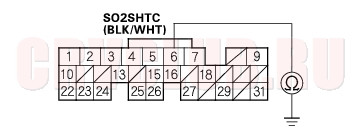
- Check continuity between body ground and secondary HO2S (Sensor 2) 4P connector terminals No. 3 and No. 4 individually.
SECONDARY HO2S (SENSOR 2) 4P CONNECTOR
Is there continuity?
Yes : Replace the secondary HO2S (Sensor 2).
No : Go to step 7.
- Turn the ignition switch ON (II).
- Measure voltage between secondary HO2S 4P connector terminals No. 3 and No. 4.
SECONDARY HO2S (SENSOR 2) 4P CONNECTOR
Terminal side of male terminals
Is there battery voltage?
Yes : Go to step 9.
No : Go to step 14.
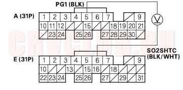
- Turn the ignition switch OFF.
- Disconnect the negative cable from the battery.
- Disconnect ECM/PCM connector E (31P).
- Reconnect the negative cable to the battery.
11-79
Is there continuity?
Yes : Repair short in the wire between the ECM/PCM (E6) and the secondary HO2S
(Sensor 2).
No : Substitute a known-good ECM/PCM and recheck (see page 11-5). If symptom/indication goes away, replace the original ECM/PCM.
SECONDARY HO2S (SENSOR 2) 4P CONNECTOR
Terminal side of male terminals
Is there battery voltage?
Yes : Go to step 15.
No : Check the No. 4 ACG (10A) fuse in the under-dash fuse/relay box. If the fuse is OK, repair open in the wire between the secondary HO2S (Sensor 2) and No. 4 ACG (10A) fuse.
- Turn the ignition switch OFF.
- Reconnect the secondary HO2S (Sensor 2) 4P connector.
- Disconnect the negative cable from the battery.
- Disconnect ECM/PCM connector E (31P).
- Reconnect the negative cable to the battery.
- Turn the ignition switch ON (II).
- Measure voltage between ECM/PCM connector terminal E6 and A5.
Is there 0.1 V or less?
Yes : Repair open in the wire between the ECM/PCM (E6) and the secondary HO2S
(Sensor 2).
No : Substitute a known-good ECM/PCM and recheck (see page 11-5). If symptom/indication goes away, replace the original ECM/PCM.
DTC Troubleshooting (cont'd)11-80
DTC P0171 (45-2): Fuel System Too Lean
DTC P0172 (45-1): Fuel System Too Rich
NOTE: If some of the DTCs listed below are stored at the same time as DTC P0171 and/or P0172, troubleshoot those DTCs first, then recheck for P0171 and/or P0172.
P0107, P0108: Manifold Absolute Pressure (MAP) sensor
P0135: Primary Heated Oxygen Sensor (primary HO2S) (Sensor 1) heater
P0137, P0138: Secondary Heated Oxygen Sensor (secondary HO2S) (sensor 1)
P0141: Secondary Heated Oxygen Sensor (secondary HO2S) (sensor 2) heater
- Check the fuel pressure (see page 11-154) .
Is fuel pressure OK?
Yes : Go to step 2.
No : Check these items:
If the pressure is too high, replace the fuel pressure regulator (see page 11-165) . If the pressure is too low, check the fuel pump, the fuel feed pipe, the fuel filter, and replace the fuel pressure regulator (see page 11-165) .
- Start the engine. Hold the engine at 3,000 rpm (min-1) with no load (in Park or neutral) until the radiator fan comes on.
- Check the primary HO2S (Sensor 1) output with the scan tool.
Does it stay at less than 0.3 V or more than 0.6 V?
Yes : Replace the primary HO2S (Sensor 1).
No : Go to step 4.
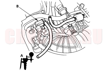
- Turn the ignition switch OFF.
- With a vacuum pump (A), apply vacuum to the evaporative emission (EVAP) canister purge valve (B) from the evaporative emission (EVAP) canister side.
Does it hold vacuum?
Yes : Go to step 6.
No : Replace the EVAP canister purge valve.
Does it indicate atmospheric pressure?
Yes : Go to step 8.
No : Replace the MAP sensor.
Is a MAP of 40.0 kPa (300 mmHg, 12.0 in.Hg) or less indicated within 1 second after starting the engine?
Yes : Check the valve clearance and adjust if necessary. If the valve clearance are OK, replace the injector.
No : Replace the MAP sensor.
11-81
DTC P0300 (7x-1): Random misfire and any Combination of the Following:
DTC P0301 (71-1): No. 1 Cylinder Misfire
DTC P0302 (72-1): No. 2 Cylinder Misfire
DTC P0303 (73-1): No. 3 Cylinder Misfire
DTC P0304 (74-1): No. 4 Cylinder Misfire
If the misfiring is frequent enough to trigger detection of increased emissions during two consecutive driving cycles, the MIL will come on, and DTC P0300 (and some combination of P0301 through P0304) will be stored. If the misfiring is frequent enough to damage the catalyst, the MIL will blink whenever the misfiring occurs, and DTC P0300 (and some combination of P0301 through P0304) will be stored. When the misfiring stops, the MIL will remain on.
- Troubleshoot the following DTCs first if any of them were stored along with the random misfire DTC(s):
- P0107, P0108: Manifold Absolute Pressure (MAP) sensor
- P0131, P0132: Primary Heated Oxygen Sensor (primary HO2S) (Sensor 1)
- P0171, P0172: Fuel system
- P0335, P0336: Crankshaft Position (CKP) sensor
- P1253: VTEC system
- P1361, P1362: Top Dead Center (TDC) sensor
- P1519: Idle Air Control (IAC) valve
- Test-drive the vehicle to verify the symptom.
- Find the symptom in the chart below, and do the related procedures in the order listed until you find the cause.
Random misfire only at low engine speed and under load Check fuel pressure (see page 11-154) .
- Low compression
- Contaminated fuel
- Manifold vacuum problem
Random misfire only during acceleration Check fuel pressure (see page 11-154) . Malfunction in the VTEC system (see page 11-130) Random misfire at high engine speed, under load, or under random conditions Check fuel pressure (see page 11-154) . Correct valve clearance (see page 06-9)
DTC Troubleshooting (cont'd)11-82
DTC P0301 (71-1): No. 1 Cylinder Misfire
DTC P0302 (72-1): No. 2 Cylinder Misfire
DTC P0303 (73-1): No. 3 Cylinder Misfire
DTC P0304 (74-1): No. 4 Cylinder Misfire
- After checking and recording the freeze data, reset the ECM/PCM (see page 11-4) . If there is no freeze data of the misfire, just clear the DTC.
- Start the engine, and listen for a clicking sound at the injector at the problem cylinder.
Does it click?
Yes : Go to step 3.
No : Go to step 32.
- Turn the ignition switch OFF, and reset the ECM/PCM.
- Exchange the ignition coil from the problem cylinder with one from another cylinder.
- Test-drive the vehicle several times in the range of the freeze data or under various conditions if there was no freeze data.
- Check the DTC or the Temporary DTC with the scan tool.
Is DTC or Temporary DTC P0301, P0302, P0303 or P0304 indicated?
Yes : Go to step 7.
No : Intermittent misfire due to poor contact at the ignition coil connector (no misfire at this time).
Does the misfire occur in the other cylinder whose ignition coil was exchanged?
Yes : Replace the faulty ignition coil.
No : Go to step 8.
- Turn the ignition switch OFF, and reset the ECM/PCM.
- Exchange the spark plug from the problem cylinder with one from another cylinder.
- Test-drive the vehicle several times in the range of the freeze data or under various conditions if there was no freeze data.
- Check the DTC or the Temporary DTC with the scan Tool.
Is DTC or Temporary DTC P0301, P0302, P0303 or P0304 indicated?
Yes : Go to step 12.
No : Intermittent misfire due to spark plug fouling, etc. (no misfire at this time).
Does the misfire occur in the other cylinder whose spark plug was exchanged?
Yes : Replace the faulty spark plug.
No : Go to step 13.
- Turn the ignition switch OFF, and reset the ECM/PCM.
- Exchange the injector from the problem cylinder with one from the another cylinder.
- Let the engine idle for 2 minutes.
11-83
- Test-drive the vehicle several times in the range of the freeze data or under various conditions if there was no freeze data.
- Check for a DTC or Temporary DTC with the scan Tool.
Is DTC or Temporary DTC P0301, P0302, P0303 or P0304 indicated?
Yes : Go to step 18.
No : Intermittent misfire due to bad contact at the injector connector (no misfire at this time).
Does the misfire occur in the other cylinder whose injector was exchanged?
Yes : Replace the faulty injector.
No : Go to step 19.
- Turn the ignition switch OFF.
- Disconnect the ignition coil 3P connector from the problem cylinder.
- Turn the ignition switch ON (II).
- Measure voltage between ignition coil 3P connector terminal No. 3 and body ground.
Is there battery voltage?
Yes : Go to step 23.
No : Repair open or short in the wire between the No. 1 IGN COIL (15A) fuse and the ignition coil.
- Turn the ignition switch OFF.
- Check for continuity between ignition coil 3P connector terminal No. 2 and body ground.
Is there continuity?
Yes : Go to step 25.
No : Repair open in the wire between the ignition coil and G101.
DTC Troubleshooting (cont'd)11-84
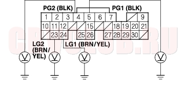
- Check for continuity between body ground and the appropriate ECM/PCM connector terminal
(see table).
No. 1 P0301 A30 YEL/GRN No. 2 P0302 A29 BLU/RED No. 3 P0303 A28 WHT/BLU No. 4 P0304 A27 BRN
Is there continuity?
Yes : Repair short in the wire between the ECM/PCM and the ignition coil.
No : Go to step 28.
- Connect the appropriate ignition coil 3P connector terminal No. 1 and body ground with a jumper wire (see table).
No. 1 P0301 YEL/GRN No. 2 P0302 BLU/RED No. 3 P0303 WHT/BLU No. 4 P0304 BRN
- Check for continuity between body ground and the appropriate ECM/PCM connector terminal
(see table).
No. 1 P0301 A30 YEL/GRN No. 2 P0302 A29 BLU/RED No. 3 P0303 A28 WHT/BLU No. 4 P0304 A27 BRN
Is there continuity?
Yes : Go to step 30.
No : Repair open in the wire between the ECM/PCM and the ignition coil.
Is the engine compression OK?
Yes : Substitute a known-good ECM/PCM and recheck (see page 11-5). If symptom/indication goes away, replace the original ECM/PCM.
No : Repair the engine.
- Disconnect the negative cable from the battery.
- Disconnect ECM/PCM connector B (24P).
- Reconnect the negative cable to the battery.
- Turn the ignition switch ON (II).
11-85
No. 1 P0301 B5 BRN No. 2 P0302 B4 RED No. 3 P0303 B3 BLU No. 4 P0304 B2 YEL
Is there battery voltage?
Yes : Go to step 37.
No : Go to step 45.
- Turn the ignition switch OFF, and remove the engine cover.
- Disconnect the injector 2P connector on the problem cylinder.
- Measure the resistance between injector 2P connector terminals No. 1 and No. 2.
Is there 10
Yes : Go to step 40.
No : Replace the injector (see page 11-117).
- Exchange the injector from the problem cylinder with one from another cylinder.
- Let the engine idle for 2 minutes.
- Test-drive the vehicle several times in the range of the freeze data or under various conditions if there was no freeze data.
- Check for a DTC or Temporary DTC with a scan tool.
Is DTC or Temporary DTC P0301, P0302, P0303, or P0304 indicated?
Yes : Go to step 44.
No : Intermittent misfire due to injector malfunction etc.
Does the misfire occur in the other cylinder whose injector was exchanged?
Yes : Replace the faulty injector.
No : Substitute a known-good ECM/PCM and recheck (see page 11-5). If symptom/indication goes away, replace the original ECM/PCM.
- Turn the ignition switch OFF and remove the engine cover.
- Disconnect the injector 2P connector on the problem cylinder.
- Turn the ignition switch ON (II).
DTC Troubleshooting (cont'd)11-86
Is there battery voltage?
Yes : Go to step 49.
No : Repair open in the wire between the injector and the PGM-FI main relay.
- Turn the ignition switch OFF.
- Check for continuity between body ground and the appropriate ECM/PCM connector terminal
(see table).
No. 1 P0301 B5 BRN No. 2 P0302 B4 RED No. 3 P0303 B3 BLU No. 4 P0304 B2 YEL
Is there continuity?
Yes : Repair short in the wire between the ECM/PCM and the injector.
No : Go to step 51.
- Connect the appropriate injector 2P connector terminal No. 2 to body ground with a jumper wire (see table).
No. 1 P0301 BRN No. 2 P0302 RED No. 3 P0303 BLU No. 4 P0304 YEL
- Check for continuity between body ground and the appropriate ECM/PCM connector terminal (see table).
No. 1 P0301 B5 BRN No. 2 P0302 B4 RED No. 3 P0303 B3 BLU No. 4 P0304 B2 YEL
Is there continuity?
Yes : Replace the injector, then recheck.
No : Repair open in the wire between the ECM/PCM and the injector.
11-87
DTC P0325 (23-1): Malfunction in Knock Sensor Circuit
- Reset the ECM/PCM (see page 11-4) .
- Start the engine. Hold the engine at 3,000 rpm (min-1) with no load (in Park or neutral) until the radiator fan comes on, then let it idle.
- Hold the engine at 3,000 - 4,000 rpm (min-1) for at least 60 seconds.
Is DTC P0325 indicated?
Yes : Go to step 4.
No : Intermittent failure, system is OK at this time. Check for poor connections or loose wires at the knock sensor and at the ECM/PCM.
- Turn the ignition switch OFF.
- Disconnect the starter sub-harness 6P connector.
- Check for continuity between ECM/PCM connector terminal A9 and body ground.
Is there continuity?
Yes : Repair short in the wire between the ECM/PCM (A9) and the starter sub-harness 6P connector.
No : Go to step 7.
Is there continuity?
Yes : Go to step 9.
No : Repair open in the wire between the ECM/PCM (A9) and the starter sub-harness 6P connector.
- Check the starter sub-harness between 6P connector and the knock sensor for an open or short. If it's OK, substitute a known-good knock sensor and recheck.
Is DTC P0325 indicated?
Yes : Substitute a known-good ECM/PCM and recheck (see page 11-5). If symptom/indication goes away, replace the original ECM/PCM.
No : Replace the original knock sensor and/or starter sub-harness.
DTC Troubleshooting (cont'd)11-88
DTC P0335 (4-1): CKP Sensor No Signal
DTC P0336 (4-2): CKP Sensor Intermittent Interruption
- Reset the ECM/PCM (see page 11-4) .
- Start the engine.
Is DTC P0335 and/or P0336 indicated?
Yes : Go to step 3.
No : Intermittent failure, system is OK at this time. Check for poor connections or loose wires at the CKP sensor and at the ECM/PCM.
- Turn the ignition switch OFF.
- Disconnect the CKP sensor 3P connector.
- Turn the ignition switch ON (II).
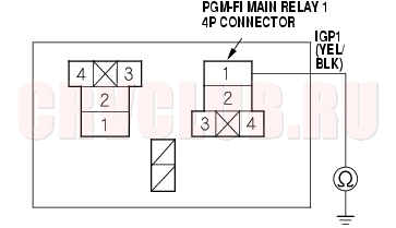
- Measure voltage between CKP sensor 3P connector terminal No. 3 and body ground.
Is there battery voltage?
Yes : Go to step 7.
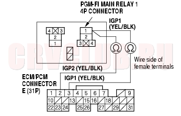
No : Repair open in the wire between the PGM-FI main relay 1 and the CKP sensor.
Is there about 5 V?
Yes : Go to step 8.
No : Go to step 10.
Is there battery voltage?
Yes : Go to step 9.
No : Repair open in the BRN/YEL wire between the CKP sensor and G101.
Is DTC P0335 and/or P0336 indicated?
Yes : Substitute a known-good ECM/PCM and recheck (see page 11-5). If symptom/indication goes away, replace the original ECM/PCM.
No : Replace the original CKP sensor.
11-89
Is there about 5 V?
Yes : Repair open in the wire between the ECM/PCM (A7) and the CKP sensor.
No : Go to step 11.
- Turn the ignition switch OFF.
- Disconnect the negative cable from the battery.
- Disconnect ECM/PCM connector A (31P).
- Check for continuity between ECM/PCM connector terminal A7 and body ground.
Is there continuity?
Yes : Repair short in the wire between the ECM/PCM (A7) and the CKP sensor.
No : Substitute a known-good ECM/PCM and recheck (see page 11-5). If symptom/indication goes away, replace the original ECM/PCM.
DTC Troubleshooting (cont'd)11-90
DTC P0500 (17-1): VSS Circuit Malfunction
DTC P0501 (17-2): VSS Range/Performance Problem
Is the correct speed indicated?
Yes : Intermittent failure, system is OK at this time. Check for poor connections or loose wires at the VSS and at the ECM.
No : Go to step 3.
- Turn the ignition switch OFF.
- Block the rear wheels and set the parking brake.
- Raise the front of the vehicle, and make sure it is securely supported.
- Turn the ignition switch ON (II).
- Block the right front wheel, and slowly rotate the left front wheel.
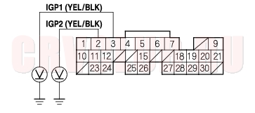
- Measure voltage between ECM/PCM connector terminals A18 and A24.
Does the voltage pulse between 0 V and 5 V or battery voltage?
Yes : Substitute a known-good ECM/PCM and recheck (see page 11-5). If symptom/indication goes away, replace the original ECM/PCM.
No : Go to step 9.
- Turn the ignition switch OFF.
- Disconnect the negative cable from the battery.
- Disconnect ECM/PCM connector A (31P).
- Reconnect the negative cable to the battery.
- Turn the ignition switch ON (II).
- Block the right front wheel, and slowly rotate the left front wheel.
- Measure voltage between ECM/PCM connector terminals A18 and A24.
Does the voltage pulse between 0 V and 5 V or battery voltage?
Yes : Substitute a known-good ECM/PCM and recheck (see page 11-5). If symptom/indication goes away, replace the original ECM/PCM.
No : Check these items:
A short or an open in the wire between the ECM/PCM (A18) and the VSS. If the wire is OK, test the VSS (see page 22A-75) . 11-91
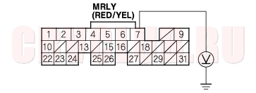
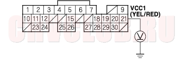
DTC P0563 (34-2): ECM/PCM Power Source Circuit Unexpected Voltage
- Reset the ECM/PCM (see page 11-4) .
- Turn the ignition switch OFF.
- Wait 5 seconds.
- Turn the ignition switch ON (II).
Is DTC P0563 indicated?
Yes : Go to step 5.
No : Intermittent failure, system is OK at this time. Check for poor connections or loose wires at the No. 6 ECU (ECM/PCM) (15A) fuse in the under-hood fuse/relay box and at the ECM/PCM.
- Turn the ignition switch OFF.
- Disconnect the negative cable from the battery.
- Disconnect ECM/PCM connector E (31P).
- Reconnect the negative cable to the battery.
- Measure voltage between ECM/PCM connector terminal E7 and body ground.
Is there battery voltage?
Yes : Go to step 13.
No : Go to step 10.
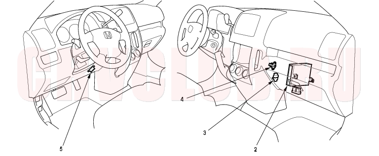
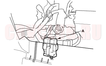
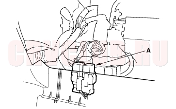
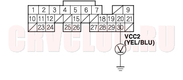
- Remove the glove box (see page 20-95) .
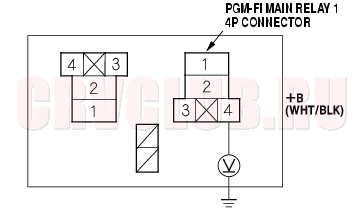
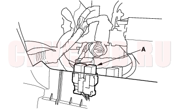
- Remove the PGM-FI main relay 1 (A).
*: The illustration shows LHD model.
Is there continuity?
Yes : Repair short in the wire between the ECM/PCM (E7) and the PGM-FI main relay 1.
No : Replace the PGM-FI main relay 1.
- Disconnect the negative cable from the battery.
- Reconnect ECM/PCM connector E (31P).
- Reconnect the negative cable to the battery.
DTC Troubleshooting (cont'd)11-92
Is there battery voltage?
Yes : Go to step 18.
No : Substitute a known-good ECM/PCM and recheck (see page 11-5). If symptom/indication goes away, replace the original ECM/PCM.
- Disconnect the negative cable from the battery.
- Disconnect ECM/PCM connector A (31P).
- Reconnect the negative cable to the battery.
- Measure voltage between body ground and ECM/PCM connector terminals A3 and A2 individually.
Is there battery voltage?
Yes : Go to step 21.
No : Substitute a known-good ECM/PCM and recheck (see page 11-5). If symptom/indication goes away, replace the original ECM/PCM.
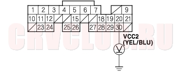
- Remove the glove box (see page 20-95) .
- Remove the PGM-FI main relay 1 (A).
*: The illustration shows LHD model.
Is there battery voltage?
Yes : Repair short to power in the wire between the ECM/PCM (A2, A3) and the PGM-FI main relay 1.
No : Replace the PGM-FI main relay 1.
11-93
DTC P1107 (13-1): BARO Sensor Circuit Low Voltage
DTC P1108 (13-2): BARO Sensor Circuit High Voltage
- Reset the ECM/PCM (see page 11-4) .
- Turn the ignition switch ON (II).
Is DTC P1107 or P1108 indicated?
Yes : Substitute a known-good ECM/PCM and recheck (see page 11-5). If symptom/indication goes away, replace the original ECM/PCM.
No : Intermittent failure, system is OK at this time.
DTC Troubleshooting (cont'd)11-94
DTC P1213 (11-1): IMA Circuit Low Voltage
- Reset the ECM/PCM (see page 11-4) .
- Start the engine, then let it idle for more than 5 seconds.
Is DTC P1213 indicated?
Yes : Go to step 3.
No : Intermittent failure, system is OK at this time. Check for poor connections or loose wires at the IMA and at the ECM/PCM.
- Turn the ignition switch OFF.
- Disconnect the IMA 3P connector.
- Turn the ignition switch ON (II).
- Measure voltage between IMA 3P connector terminals No. 1 and No. 3.
Is there about 5 V?
Yes : Go to step 7.
No : Go to step 15.
- Turn the ignition switch OFF.
- Disconnect the negative cable from the battery.
- Disconnect ECM/PCM connector E (31P).
- At the wire harness side, check for continuity between IMA 3P connector terminal No. 2 and body ground.
Is there continuity?
Yes : Repair short in the wire between the ECM/PCM (E15) and the IMA.
No : Go to step 11.
- Reconnect the IMA 3P connector and ECM/PCM connector E (31P).
- Reconnect the negative cable to the battery.
- Turn the ignition switch ON (II).
11-95
Is there about 0.5 - 4.5 V?
Yes : Substitute a known-good ECM/PCM and recheck (see page 11-5). If the symptom/indication goes away with a known-good ECM/PCM, replace the original ECM/PCM.
No : Replace the IMA.
Is there about 5 V?
Yes : Repair open in the wire between the ECM/PCM (E5) and the IMA.
No : Substitute a known-good ECM/PCM and recheck (see page 11-5). If the symptom/indication goes away with a known-good ECM/PCM, replace the original ECM/PCM.
DTC P1214 (11-2): IMA Circuit High Voltage
- Reset the ECM/PCM (see page 11-4) .
- Start the engine, then let it idle for more than 5 seconds.
Is DTC P1214 indicated?
Yes : Go to step 3.
No : Intermittent failure, system is OK at this time. Check for poor connections or loose wires at the IMA and at the ECM/PCM.
- Turn the ignition switch OFF.
- Disconnect the IMA 3P connector.
- Turn the ignition switch ON (II).
- Measure voltage between IMA 3P connector terminals No. 1 and No. 3.
Is there about 5 V?
Yes : Go to step 8.
No : Go to step 7.
DTC Troubleshooting (cont'd)11-96
Is there about 5 V?
Yes : Repair open in the wire between the ECM/PCM (E4) and the IMA.
No : Substitute a known-good ECM/PCM and recheck (see page 11-5). If the symptom/indication goes away with a known-good ECM/PCM, replace the original ECM/PCM.
- At the wire harness side, check for continuity between IMA 3P connector terminals No. 2 and body ground.
Is there continuity?
Yes : Replace the IMA.
No : Repair open in the wire between the ECM/PCM (E15) and the IMA.
11-97
DTC P1297 (20-1): ELD Circuit Low Voltage
- Reset the ECM/PCM (see page 11-4) .
- Start the engine.
- Turn on the headlights.
Is DTC P1297 indicated?
Yes : Go to step 4.
No : Intermittent failure, system is OK at this time. Check for poor connections or loose wires at the ELD and at the ECM/PCM.
- Turn the ignition switch and the headlights OFF.
- Disconnect the ELD 3P connector.
- Turn the ignition switch ON (II).
- Measure voltage between body ground and ELD 3P connector terminal No. 3.
Is there about 5 V?
Yes : Replace the ELD.
No : Go to step 8.
- Turn the ignition switch OFF.
- Disconnect the negative cable from the battery.
- Disconnect ECM/PCM connector E (31P).
- Check for continuity between body ground and ECM/PCM connector terminal E15.
Is there continuity?
Yes : Repair short in the wire between the ECM/PCM (E15) and the ELD.
No : Substitute a known-good ECM/PCM and recheck (see page 11-5). If symptom/indication goes away, replace the original ECM/PCM.
DTC Troubleshooting (cont'd)11-98
DTC P1298 (20-2): ELD Circuit High Voltage
- Reset the ECM/PCM (see page 11-4) .
- Start the engine.
- Turn on the headlights.
Is DTC P1298 indicated?
Yes : Go to step 4.
No : Intermittent failure, system is OK at this time. Check for poor connections or loose wires at the ELD and at the ECM/PCM.
- Turn the ignition switch and headlights OFF.
- Disconnect the ELD 3P connector.
- Turn the ignition switch ON (II).
- Measure voltage between body ground and ELD 3P connector terminal No. 1.
Is there battery voltage?
Yes : Go to step 8.
No : Check the No. 4 ACG (10A) fuse in the under-dash fuse/relay box. If the fuse is OK, repair open in the wire between the No. 4 ACG (10A) fuse and the ELD.
- Turn the ignition switch OFF.
- Connect ELD 3P connector terminal No. 3 to body ground with a jumper wire.
- Disconnect ECM/PCM connector E (31P).
- Disconnect the negative cable from the battery.
- Check for continuity between body ground and ECM/PCM connector terminal E15.
Is there continuity?
Yes : Go to step 13.
No : Repair open in the wire between the ECM/PCM (E15) and the ELD.
11-99
Is there continuity?
Yes : Go to step 14.
No : Repair open in the wire between ELD and G201.
- Reconnect the ELD 3P connector and ECM/PCM connector E (31P).
- Reconnect the negative cable to the battery.
- Start the engine and let it idle.
- While measuring voltage between ECM/PCM connector terminals A24 and E15, turn the headlights on (high).
Does the voltage drop?
Yes : Substitute a known-good ECM/PCM and recheck (see page 11-5). If symptom/indication goes away, replace the original ECM/PCM.
No : Replace the ELD.
DTC Troubleshooting (cont'd)11-100
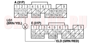
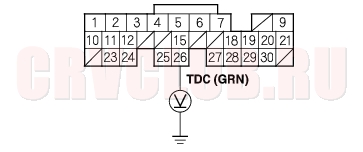
DTC P1361 (8-2): TDC Sensor Intermittent Interruption
DTC P1362 (8-1): TDC Sensor No Signal
- Reset the ECM/PCM (see page 11-4) .
- Start the engine.
Is DTC P1361 and/or P1362 indicated?
Yes : Go to step 3.
No : Intermittent failure, system is OK at this time. Check for poor connections or loose wires at the TDC sensor and at the ECM/PCM.
- Turn the ignition switch OFF.
- Disconnect the TDC sensor 3P connector.
- Turn the ignition switch ON (II).
- Measure voltage between TDC sensor 3P connector terminal No. 3 and body ground.
Is there battery voltage?
Yes : Go to step 7.
No : Repair open in the wire between the PGM-FI main relay 1 and the TDC sensor.
Is there about 5 V?
Yes : Go to step 8.
No : Go to step 10.
Is there battery voltage?
Yes : Go to step 9.
No : Repair open in the BRN/YEL wire between the TDC sensor and G101.
Is DTC P1361 and/or P1362 indicated?
Yes : Substitute a known-good ECM/PCM and recheck (see page 11-5). If symptom/indication goes away, replace the original ECM/PCM.
No : Replace the original TDC sensor.
11-101
Is there about 5 V?
Yes : Repair open in the wire between the ECM/PCM (A26) and TDC sensor.
No : Go to step 11.
- Turn the ignition switch OFF.
- Disconnect the negative cable from the battery.
- Disconnect ECM/PCM connector A (31P).
- Check for continuity between ECM/PCM connector terminal A26 and body ground.
Is there continuity?
Yes : Repair short in the wire between the ECM/PCM (A26) and the TDC sensor.
No : Substitute a known-good ECM/PCM and recheck (see page 11-5). If symptom/indication goes away, replace the original ECM/PCM.
DTC P1607 (0-2): Malfunction in ECM/PCM Internal Circuit
- Reset the ECM/PCM (see page 11-4) .
- Turn the ignition switch ON (II).
- Wait 40 seconds.
Is DTC P1607 indicated?
Yes : Substitute a known-good ECM/PCM and recheck (see page 11-5). If symptom/indication goes away, replace the original ECM/PCM.
No : Intermittent failure, system is OK at this time.
MIL Circuit Troubleshooting11-102
- Connect a scan tool/Honda PGM Tester (see page 11-3) .
- Turn the ignition switch ON (II) and read the scan tool/Honda PGM Tester.
Does the the scan tool/Honda PGM Tester communicate with the ECM/PCM?
Yes : Go to step 3.
No : Go to troubleshooting ''DLC circuit'' (see page 11-114).
Are any DTCs indicated?
Yes : Go to the DTC Troubleshooting Index.
No : Go to step 4.
- Turn the ignition switch OFF.
- Turn the ignition switch ON (II) and watch the Malfunction Indicator Lamp (MIL).
Does the MIL come on and stay on?
Yes : If the MIL always come on and stays on, go to step 77. But if the MIL sometimes works normally, first check for these problems:
An intermittent short in the wire between the ECM/PCM (E29) and the Data Link Connector (DLC). An intermittent short in the wire between the ECM/PCM (E31) and the gauge assembly. No : If the MIL is always off, go to step 6. But if the MIL sometimes works normally, first check for these problems:
A loose No. 10 METER (7.5A) fuse in the under-dash fuse/relay box. A loose No. 20 IG (50A) fuse in the under-hood fuse/relay box. A loose No. 6 ECU (ECM/PCM) (15A) fuse in the under-hood fuse/relay box. A loose No. 17 FUEL PUMP (15A) fuse in the under-dash fuse/relay box. A poor connection at ECM/PCM terminal E31. An intermittent open in the GRN/WHT wire between the ECM/PCM (E31) and the gauge assembly. An intermittent short in the wire between the ECM/PCM (A21) and the manifold absolute pressure (MAP) sensor, countershaft speed sensor (A/T). An intermittent short in the wire between the ECM/PCM (A20) and the throttle position (TP) sensor, mainshaft speed sensor (A/T). An intermittent short in the wire between the ECM/PCM (E5) and the idle mixture adjuster (IMA) (without TWC). 11-103
- KG, KS, KE, KR models:
Turn the ignition switch OFF and press the inertia switch button.
- KG, KS, KE, KR models:
Turn the ignition switch ON (II).
Does the MIL come on for 2 seconds after the ignition switch is turned ON (II)?
Yes : Intermittent failure system is OK at this time.
No : Go to step 8.
- KG, KS, KE, KR models:
Turn the ignition switch OFF and disconnect the inertia switch 3P connector.
- KG, KS, KE, KR models:
Connect inertia switch 3P connector terminals No. 1 and No. 3 with a jumper wire.
Does the MIL come on for 2 seconds after the ignition switch is turned ON (II)?
Yes : Replace the inertia switch.
No : Go to step 11.
Is the low oil pressure light on?
Yes : Go to step 15.
No : Go to step 13.
Is the fuse OK?
Yes : Go to step 14.
No : Repair short in the wire between No. 10 METER (7.5A) fuse and the gauge assembly. Also replace the No. 10 METER (7.5A) fuse.
Is the fuse OK?
Yes : Repair open in the wire between the No. 20 IG (50A) fuse and the gauge assembly. If the wires are OK, test the ignition switch (see page 22A-63).
No : Repair short in the wire between the No. 20 IG (50A) fuse and the under-hood fuse/relay box. Also replace the No. 20 IG (50A) fuse.
Does the engine start?
Yes : Go to step 16.
No : Go to step 18.
MIL Circuit Troubleshooting (cont'd)11-104
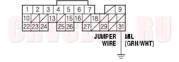
- Turn the ignition switch OFF. Connect ECM/PCM connector terminal E31 to body ground with a jumper wire.
Is the MIL on?
Yes : Substitute a known-good ECM/PCM and recheck (see page 11-5). If the symptom/indication goes away, replace the original ECM/PCM.
No : Check for an open in the wires between the ECM/PCM (E31) and the gauge assembly. Also check for a blown MIL bulb. If the wires and the bulb are OK, replace the gauge assembly.
- Turn the ignition switch OFF.
- Remove and inspect the No. 6 ECU (ECM/PCM) (15A) fuse in the under-hood fuse/relay box.
Is the fuse OK?
Yes : Go to step 25.
No : Go to step 20.
- Remove the glove box (see page 20-95) , PGM-FI main relay 1 (A).
*: The illustration shows LHD model.
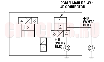
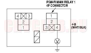
- Check for continuity between body ground and PGM-FI main relay 1 4P connector terminals No. 2 and No. 4 individually.
Is there continuity?
Yes : Repair short in the wire between the No. 6 ECU (ECM/PCM) (15A) fuse and the PGM-FI main relay 1. Also replace the No. 6 ECU (ECM/PCM) (15A) fuse.
No : Go to step 22.
11-105
- Disconnect each of the component or the connector sensors below, one at a time, and check for continuity between the PGM-FI main relay 1 4P connector terminal No. 1 and body ground.
- PGM-FI main relay 2
- ECM/PCM connector A (31P)
- Each injector 2P connector
- Idle air control (IAC) valve 3P connector
- Top dead center (TDC) sensor 2P connector
- Crankshaft position (CKP) sensor 3P connector
Is there continuity?
Yes : Go to step 23.
No : Replace the item that made continuity to body ground go away when disconnected. If the item is the ECM/PCM, substitute a known-good ECM/PCM and recheck
(see page 11-5). If the symptom/indication goes away, replace the original ECM/PCM.
Also replace the No. 6 ECU (ECM/PCM) (15A) fuse.
- Disconnected the connectors of all following items.
- PGM-FI main relay 2
- ECM/PCM connector A (31P)
- Injectors
- Idle air control (IAC) valve
- Top dead center (TDC) sensor
- Crankshaft position (CKP) sensor
- Check for continuity between PGM-FI main relay 1 4P connector terminals No. 1 and body ground.
Is there continuity?
Yes : Repair short in the wire between PGM-FI main relay 1 and each item. Also replace the No. 6 ECU (ECM/PCM) (15A) fuse.
No : Replace the PGM-FI main relay 1. Also replace the No. 6 ECU (ECM/PCM) (15A) fuse.
Is the fuse OK?
Yes : Go to step 36.
No : Go to step 26.
MIL Circuit Troubleshooting (cont'd)11-106
Is there continuity?
Yes : Go to step 29.
No : Replace the No. 17 FUEL PUMP (15A) fuse, and substitute a known-good ECM/PCM and recheck (see page 11-5). If the symptom/indication goes away, replace the original ECM/PCM.
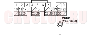
- Remove the glove box (see page 20-95) , PGM-FI main relay 2 (A).
*: The illustration shows LHD model
Is there continuity?
Yes : Repair short in the wire between the No. 17 FUEL PUMP (15A) fuse and the ECM/PCM (E9), or the No. 17 FUEL PUMP (15A) fuse and the PGM-FI main relay 2. Also replace the No. 17 FUEL PUMP (15A) fuse.
No : Go to step 31.
- Fold the rear seats forward, and pull back the carpet to expose the access panel.
- Remove the access panel from the floor. Disconnect the fuel pump 5P connector.
11-107
Is there continuity?
Yes : Repair short in the wire between the fuel pump and the PGM-FI main relay 2. Also replace the No. 17 FUEL PUMP (15A) fuse.
No : Go to step 34.
*: The illustration shows LHD model
Is there continuity?
Yes : Replace PGM-FI main relay 2. Also replace the No. 17 FUEL PUMP (15A) fuse.
No : Check the fuel pump, and replace it if necessary. Also replace the No. 17 FUEL PUMP (15A) fuse.
- Disconnect the negative cable from the battery.
- Disconnect ECM/PCM connector E (31P).
- Reconnect the negative cable to the battery.
- Turn the ignition switch ON (II).
- Measure voltage between ECM/PCM connector terminals E9 and body ground.
Is there battery voltage?
Yes : Go to step 41.
No : Repair open in the wire between the No. 17 FUEL PUMP (15A) fuse and the ECM/PCM (E9).
MIL Circuit Troubleshooting (cont'd)11-108
Is there battery voltage?
Yes : Go to step 45.
No : Go to step 42.
*: The illustration shows LHD model.
Is there battery voltage?
Yes : Go to step 44.
No : Repair open in the wire between the No. 6 ECU (ECM/PCM) (15A) fuse and PGM-FI main relay 1.
- Check for continuity between PGM-FI main relay 1 4P connector terminal No. 3 and ECM/PCM connector terminal E7.
Is there continuity?
Yes : Test PGM-FI main relay 1 (see page 22A-60). If the relay is OK, substitute a known-good ECM/PCM and recheck (see page 11-5). If the symptom/indication goes away, replace the original ECM/PCM.
No : Repair open in the wire between PGM-FI main relay 1 and the ECM/PCM (E7).
11-109
- Disconnect the negative cable from the battery.
- Reconnect ECM/PCM connector E (31P).
- Reconnect the negative cable to the battery.
- Turn the ignition switch ON (II).
- Measure voltage between body ground and ECM/PCM connector terminals A2 and A3 individually.
Is there battery voltage?
Yes : Go to step 55.
No : Go to step 50.
*: The illustration shows LHD model
- Turn the ignition switch ON (II).
- Measure voltage between PGM-FI main relay 1 4P connector terminal No. 2 and body ground.
Is there battery voltage?
Yes : Go to step 53.
No : Repair open in the wire between the No. 6 ECU (ECM/PCM) (15A) fuse and PGM-FI main relay 1.
- Turn the ignition switch OFF.
- Check for continuity between PGM-FI main relay 1 4P connector terminal No. 1 and ECM/PCM connector terminals A2 and A3 individually.
Is there continuity?
Yes : Replace the PGM-FI main relay 1.
No : Repair open in the wire between PGM-FI main relay 1 and the ECM/PCM (A2, A3).
MIL Circuit Troubleshooting (cont'd)11-110
- Measure voltage between body ground and ECM/PCM connector terminals A4, A5, A23 and A24 individually.
Is there less than 0.2 V?
Yes : Repair open in the wire(s) that had more than 0.2 V between G101 and ECM/PCM (A4, A5, A23, A24).
No : Go to step 56.
Is there about 5 V?
Yes : Go to step 63.
No : Go to step 57.
- Turn the ignition switch OFF.
- Disconnect the 3P connector from each of these sensors, one at a time, and measure voltage between body ground and ECM/PCM connector terminal A21 with the ignition switch ON (II).
- Manifold absolute pressure (MAP) sensor
- Countershaft speed sensor (A/T)
Is there about 5 V?
Yes : Replace the sensor that restored 5 V when disconnected.
No : Go to step 59.
- Turn the ignition switch OFF and disconnect the negative cable from the battery.
- Disconnect the 3P connectors from the following sensors.
- Manifold absolute pressure (MAP) sensor
- Countershaft speed sensor (A/T)
- Disconnect ECM/PCM connector A (31P).
11-111
Is there continuity?
Yes : Repair short in the wire between ECM/PCM (A21) and the MAP sensor, countershaft speed sensor (A/T).
No : Substitute a known-good ECM/PCM and recheck (see page 11-5). If the symptom/indication goes away, replace the original ECM/PCM.
Is there about 5 V?
Yes : Go to step 70.
No : Go to step 64.
- Turn the ignition switch OFF.
- Disconnect the 3P connector from each of these sensors, one at a time, and measure voltage between body ground and ECM/PCM connector terminal A20 with the ignition switch ON (II).
- Throttle position (TP) sensor
- Mainshaft speed sensor (A/T)
Is there about 5 V?
Yes : Replace the sensor that restored 5 V when disconnected.
No : Go to step 66.
- Turn the ignition switch OFF and disconnect the negative cable from the battery.
- Disconnect the 3P connector from the following sensors.
Throttle position (TP) sensor Mainshaft speed sensor (A/T) MIL Circuit Troubleshooting (cont'd)11-112
Is there continuity?
Yes : Repair short in the wire between the ECM/PCM (A20) and the TP sensor, mainshaft speed sensor (A/T).
No : Substitute a known-good ECM/PCM and recheck (see page 11-5). If symptom/indication goes away, replace the original ECM/PCM.
Is there about 5 V?
Yes : Substitute a known-good ECM/PCM and recheck (see page 11-5). If the symptom/indication goes away, replace the original ECM/PCM.
No : Go to step 71.
- Turn the ignition switch OFF and disconnect the idle mixture adjuster (IMA) 3P connector.
- Turn the ignition switch ON (II).
- Measure voltage between body ground and ECM/PCM connector terminal E5.
Is there about 5 V?
Yes : Replace the IMA.
No : Go to step 74.
- Turn the ignition switch OFF and disconnect the negative cable from the battery.
- Disconnect ECM/PCM connector E (31P).
- Check for continuity between ECM/PCM connector terminal E5 and body ground.
Is there continuity?
Yes : Repair short in the wire between ECM/PCM (E5) and the IMA.
No : Substitute a known-good ECM/PCM and recheck (see page 11-5). If the symptom/indication goes away, replace the original ECM/PCM.
11-113
- Turn the ignition switch OFF.
- Turn the ignition switch ON (II).
- Measure voltage between ECM/PCM connector terminal E29 and body ground.
Is there about 5 V (or battery voltage)?
Yes : Go to step 83.
No : Go to step 80.
- Turn the ignition switch OFF and disconnect the negative cable from the battery.
- Disconnect the ECM/PCM connector E (31P).
- Check for continuity between ECM/PCM connector terminal E29 and body ground.
Is there continuity?
Yes : Repair short in the wire between the data link connector and the ECM/PCM (E29).
No : Substitute a known-good ECM/PCM and recheck (see page 11-5). If symptom/indication goes away, replace the original ECM/PCM.
- Turn the ignition switch OFF and disconnect the negative cable from the battery.
- Disconnect the ECM/PCM connector E (31P).
- Reconnect the negative cable to the battery.
- Turn the ignition ON (II).
Is the MIL ON?
Yes : Repair short in the wire between the gauge assembly and the ECM/PCM (E31). If the wires are OK, replace the gauge assembly.
No : Substitute a known-good ECM/PCM and recheck (see page 11-5). If symptom/indication goes away, replace the original ECM/PCM.
DLC Circuit Troubleshooting11-114
- Turn the ignition switch ON (II).
- Measure voltage between data link connector (DLC) terminal No. 16 and body ground.
Is there battery voltage?
Yes : Go to step 3.
No : Repair open in the wire between DLC terminal No. 16 and the No. 9 BACK UP (10A) fuse in the under-hood fuse/relay box.
Is there battery voltage?
Yes : Go to step 4.
No : Repair open in the wire between DLC terminal No. 4 and body ground.
Is there battery voltage?
Yes : Go to step 5.
No : Repair open in the wire between DLC terminal No. 5 and the ECM/PCM (E3).
Is there 8.5 V or more?
Yes : Go to step 11.
No : Go to step 6.
11-115
- Disconnect ECM/PCM connector E (31P). Make sure the Honda PGM Tester is disconnected from the DLC.
- Check for continuity between DLC terminal No. 7 and body ground.
Is there continuity?
Yes : Repair short to ground in the wire between DLC terminal No. 7 and the ECM/PCM (E23).
No : Go to step 10.
Is there continuity?
Yes : Substitute a known-good ECM/PCM, and recheck (see page 11-5). If the symptom/indication goes away with a known-good ECM/PCM, replace the original ECM/PCM.
No : Repair open in the wire between DLC terminal No. 7 and the ECM/PCM (E23).
- Turn the ignition switch OFF.
- Disconnect the negative cable from the battery.
- Disconnect ECM/PCM connector E (31P). Make sure the Honda PGM Tester is disconnected from the DLC.
- Reconnect the negative cable to the battery.
- Turn the ignition switch ON (II).
- Measure voltage between DLC terminals No. 5 and No. 7.
Is there 0 V?
Yes : Substitute a known-good ECM/PCM, and recheck (see page 11-5). If the symptom/indication goes away with a known-good ECM/PCM, replace the original ECM/PCM.
No : Repair short to power in the wire between the DLC terminal No. 7 and the ECM/PCM (E23).
Injector Test11-116
NOTE: Check the following items before testing: idle speed, ignition timing and idle CO%.
Does the engine start?
Yes : Go to step 2.
No : Go to step 6.
- Turn the ignition switch OFF. Remove the engine cover.
- Disconnect each injector connector individually.
- Inspect the change in the idle speed.
If the idle speed drop is almost the same for each cylinder, the fuel injectors are normal. If the idle speed or quality remains the same when you disconnect a particular injector, replace the injector and retest (see page 11-117) .
- Check the clicking sound of each injector by means of a stethoscope when the engine is idling.
- If any fuel injector fails to make the typical clicking sound, check the sound again after replacing the injector (see page 11-117) .
- If clicking sound is still absent, check the following.
- Whether there is wire breakage or poor connection in the YEL/BLK wire between the PGM-FI main relay and the junction connector.
- Whether the junction connector is open or corroded.
- Whether there is wire breakage or poor connection in the YEL/BLK wire between the junction connector and the injector.
- Whether there is any short-circuiting, wire breakage or poor connection in the wire between the injector and the ECM/PCM.
- If all is OK, the test is complete.
- Turn the ignition switch OFF.
- Remove the engine cover.
- Remove the injector connector.
- Measure the resistance between injector (A) terminals No. 1 and No. 2.
Is there 10 - 13
Yes : Go to step 10.
No : Replace the injector (see page 11-117).
- 10. Check the fuel pressure (see page 11-154) .
If the fuel pressure is as specified, check the following:
Whether there is wire breakage, or poor connection in the YEL/BLK wire between the PGM-FI main relay and the junction connector. Whether the junction connector is open or corroded. Whether there is wire breakage, or poor connection in the YEL/BLK wire between the junction connector and the injector. Whether there is any short-circuiting, wire breakage or poor connection in the wire between the injector and the ECM/PCM. If the fuel pressure is not as specified, recheck the fuel pressure (see page 11-154) . Injector Replacement11-117
- Relieve fuel pressure (see page 11-154) .
- Disconnect the connectors from the injectors (A), ground cable (B).
- Disconnect the quick-connect fittings (C).
- Remove the fuel rail mounting nuts (D) from the fuel rail (E).
- Remove the injector clip (F) from the injector.
- Remove the injector from the fuel rail.
Injector Replacement (cont'd)11-118
- Coat the new O-rings (A) with clean engine oil, and insert the injectors (B) into the fuel rail (C).
- Install the injector clip (D).
- Coat the injector O-ring (E) with clean engine oil.
- To prevent damage to the O-rings, install the injectors in the fuel rail first, then install them in the injector base (F).
- Install the fuel rail mounting nuts and ground cable.
- Connect the connectors on the injectors.
- Connect the quick-connect fittings.
- Turn the ignition switch ON (II), but do not operate the starter. After the fuel pump runs for approximately 2 seconds, the fuel pressure in the fuel line rises. Repeat this two or three times, then check for fuel leakage.
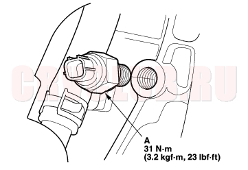
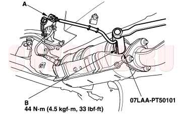
Primary HO2S Replacement11-119
Special Tools Required
O2 sensor wrench 07LAA-PT50101
KG, KS, KE, KR, KU, KZ, FO, KQ models:
KN, KM, KY, MA, PH, IN, KK models.
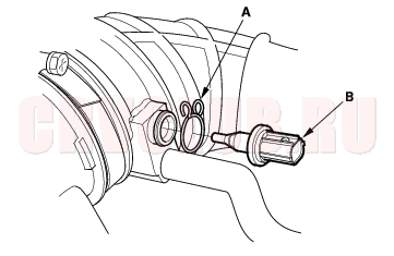
CKP Sensor Replacement11-119
- Disconnect the CKP 3P connector.
- Remove the CKP sensor (A).
- Install the part in the reverse order of removal with a new O-ring (B).
ECT Sensor Replacement11-120
- Remove the air cleaner (see page 11-182) .
- Disconnect the ECT sensor 2P connector.
- Remove the ECT sensor (A).
- Install the part in the reverse order of removal with a new O-ring (B).
TDC Sensor Replacement11-120
- Remove the air cleaner (see page 11-182) .
- Disconnect the TDC sensor 3P connector.
- Remove the TDC sensor (A).
- Install the part in the reverse order of removal with a new O-ring (B).
IAT Sensor Replacement11-121
- Disconnect the IAT sensor 2P connector.
- Remove the clip (A) and the IAT sensor (B).
- Install the part in the reverse order of removal.
Knock Sensor Replacement11-121
- Remove the splash shield.
- Disconnect the knock sensor 1P connector.
- Remove the knock sensor (A).
- Install the part in the reverse order of removal.
Secondary HO2S Replacement11-122
Special Tools Required
|
Fuel and Emissions11-1
PGM-FI System11-59 |